Dynamic Mechanical Behavior and Numerical Simulation of an Ancient Underground Rock Mass under Impact Loading
Baoping Zou,Zhiping Liu,Weifeng Jin,Haonan Ding and Zhanyou Luo
School of Civil Engineering and Architecture,Zhejiang University of Science and Technology,Hangzhou,310023,China
ABSTRACT To study the dynamic mechanical properties of tuffunder different environmental conditions, the tufffrom an ancient quarry in Shepan Island was prepared.The impact damage to the rock was tested using a triaxial dynamic impact mechanical testing system(TDIMTS)with different ground stresses,temperatures,and groundwater pressures.The time-strain relationship,dynamic stress-strain relationship,energy dissipation law,energy-peak strain relationship,and the impact damage pattern of the tuffspecimens under impact air pressures were investigated.The TDIMTS experiment on ancient underground rock mass under impact loading was also simulated using the finite element analysis software LS-DYNA based on the Holmquist-Johnson-Cook (HJC) material model.The dynamic failure process,failure pattern and peak stress of tuffspecimen were calculated.The simulation results obtained using the above methods were in good agreement with the experimental results.The results of the dynamic experiment show that with the same local stress, groundwater pressure, and temperature, the damage to the tuffspecimens caused by blasting and quarrying disturbances gradually increases as the impact pressure increases.Under the same local stress, groundwater pressure, and temperature, the energy required to rupture the tuffs in ancient underground caverns is relatively small if the impact pressure is low accordingly, but as the impact pressure increases,the damage to the tuffcaused by quarrying disturbance gradually increases.The damage gradually increases and the degree of damage to the tuffand the strain energy exhibit asymptotic growth when the tuffspecimens are subjected to the greater strain energy,increasing the degree of rupturing of the tuff.In addition,the average crushing size decreases with increasing strain energy.By comparing the simulation results with the experimental results,it was found that the HJC model reflected the dynamic impact performance of tuffspecimen,and the simulation results showed an evident strain rate effect.These results of this study can offer some guidance and theoretical support for the stability evaluation, protection, and safe operation of the ancient underground caverns in future.
KEYWORDS Ancient underground caverns; numerical simulation; thermal-hydraulic-mechanical coupling; dynamic impact;tuff;stability of surrounding rock
1 Introduction
Ancient underground engineering cave chambers are a class of immovable cultural relics [1],and they are the best physical evidence of the prosperity of the quarrying industry and the high mining techniques in ancient Chinese society.The distribution of caverns in ancient underground engineering is shown in Table 1(This is also an ancient underground project that China has developed).The above ancient underground cavern groups have common characteristics.They are all artificially excavated, which belong to shallow and ultra-shallow underground engineering and have special cavern structure.The stability of the rock surrounding these caverns is not only directly related to the operation and safety of ancient underground cave chamber,but it also determines the development and conservation of the entire ancient underground cave chamber.To date,studies of ancient underground cavern chambers have mainly focused on the hydrological engineering geological conditions,stability evaluation[2–4],geological hazard prevention,and long-term protection[5,6].Studies have also been conducted on the damage mechanical properties of rock masses.However,most of these studies have focused on static mechanical properties.Zhang et al.[7] analyzed the characteristics of the particle size distribution, the disintegration resistance index, and the swelling discriminatory characteristics of dry disintegrates in ancient underground cave chambers.Gao et al.[8] studied the mechanism of vault fracture development in ancient underground cave chambers in Longyou using a multi-factor approach.Gao et al.[9] studied the mechanism and pattern of fracture development in the roof of Cave 3 in the Longyou Grotto.
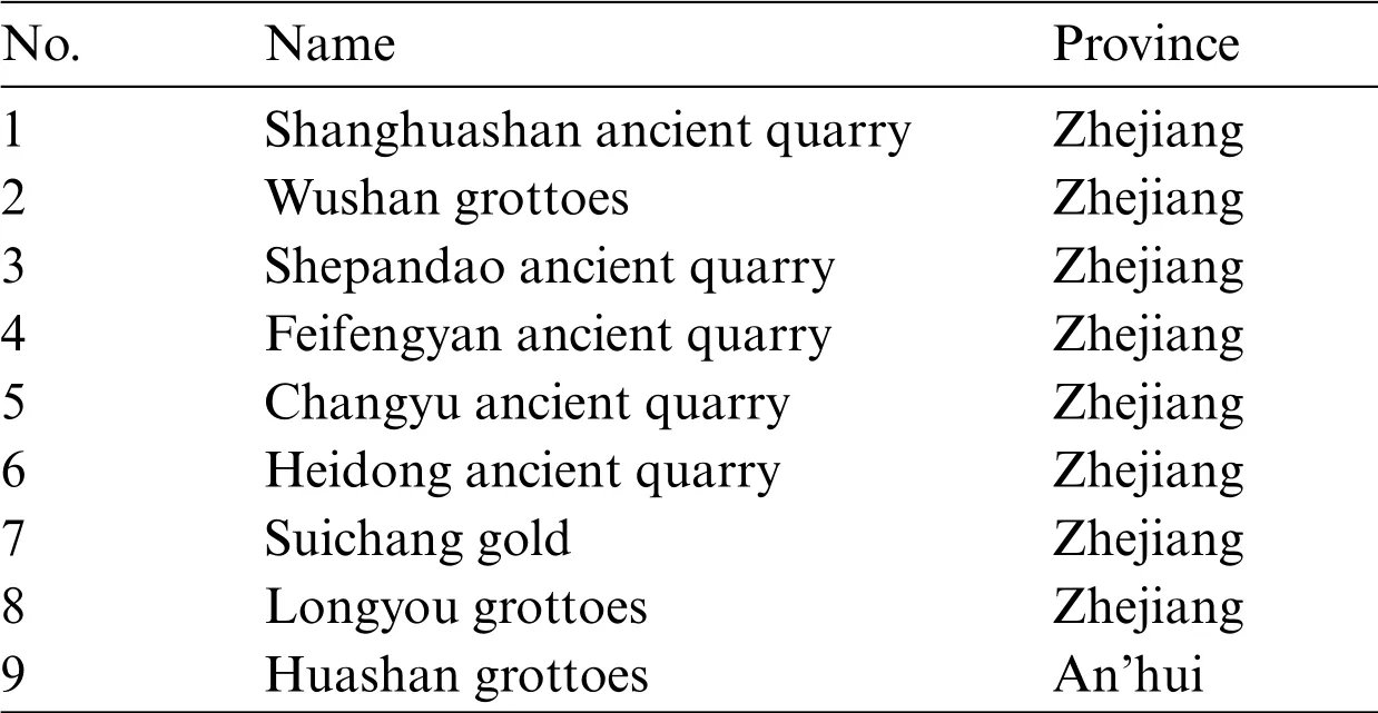
Table 1:Distribution of caverns in ancient underground engineering of China
In fact,all of the ancient underground chambers discovered so far have been quarried(blasted and excavated)to different degrees or on different scales in recent modern times and are a partially waterfilled or water-filled[1].The influences of the complex geological environment(seepage,temperature,and stress fields) and engineering disturbances on the long-term stability of underground caverns cannot be ignored.For example,Yang et al.[10]studied the stress wave propagation characteristics,dynamic stress-strain relationship, and energy dissipation law of a laminated composite rock body composed of a combination of red sandstone and grey sandstone.Zou et al.[11] studied the dynamic stress-strain characteristics and the correlation between the dynamic deformation modulus and the loading rate, as well as the dependence of the peak stress/strain on the loading rate, the axial and confining pressures, the hydraulic pressure, the temperature and the absorption energy.Xu et al.[12] investigated the dynamic compressive mechanical properties of concrete under true triaxial confinement.Selyutina et al.[13] explored the fracture properties of saturated concrete and rock under dynamic loading.Wang et al.[14] explored the dynamic compressive damage properties of rock unloading.Long et al.[15,16] investigated the dynamic constitutive behaviour for different strain rates using the split-Hopkinson pressure bar with the applied gas gun pressure.Liu et al.[17] studied the drop impact and thermal cycling of electronic packaging structures.However, the ancient underground cavern chambers were all excavated artificially,and they all have self-stabilization times of hundreds or even thousands of years, while the engineering geological and hydrogeological conditions of the surrounding rock,the environmental conditions,and the long-term strength of the rock material have changed.The existing research results can hardly meet the development needs of the ancient underground cavern chambers.It is necessary to carry out experimental studies on the dynamic impact mechanical properties of ancient underground cavern rock masses under coupled ground stress,temperature,and groundwater conditions.
Therefore, in this study, tuff samples from Shepandao in Zhejiang Province were taken as an example, and the dynamic rupture characteristics of the tuff were analyzed by testing the dynamic impact force characteristics of the tuff under different coupled ground stress, temperature, and groundwater pressure conditions using a self-developed triaxial dynamic impact mechanics testing system.The results of this study provide a theoretical basis for the long-term stability evaluation,protection,and safe operation of ancient underground caverns.
2 Experimental Research
2.1 Specimen Preparation
The tests were carried out on tuff collected from the ancient underground quarry in Shepang Island,Zhejiang Province.The ancient underground caverns are shown in Fig.1.Sample processing preparation is shown in Fig.2.The tests were conducted in accordance with the Standard for Test Methods of Engineering Rock (GBT50266-2013) and the recommendations of the International Society of Rock Mechanics(ISRM)[18].Aφ96 mm×48 mm disc specimen was used for the dynamic compression deformation test, aφ50 mm × 100 mm cylindrical specimen was used for the static uniaxial compressive strength test, and aφ50 mm × 25 mm cylindrical specimen was used for the static splitting tensile strength test.The uniaxial compressive strength and tensile strength tests were carried out usingφ50 mm×25 mm cylindrical specimens,and the loading rate for both the uniaxial compressive strength and tensile strength tests was 0.5 MPa/s.No fewer than three specimens were used for each group of rocks in each type of test.The test results obtained were processed,and the average values were used.The physical and mechanical parameters of the rocks are presented in Table 2.After testing,the static stress of the sample is 91.245 Mpa.During the processing,the rocks were processed into parallel laminated surfaces according to the original rock layer of the tuff.The two ends of the rock samples were polished using a self-developed rock and soil cutting and grinding machine(Fig.3)to control the non-parallelism and non-verticality of the ends of the rock samples to within±0.02 mm.The main advantage of cutting and grinding machine is that the cutter can move freely to achieve any height and width of the rock cutting and grinding.Rock cutting sizes range from 20 to 300 mm.
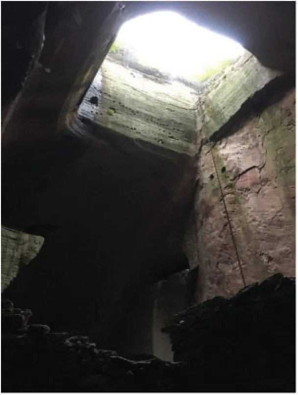
Figure 1:Ancient underground caverns
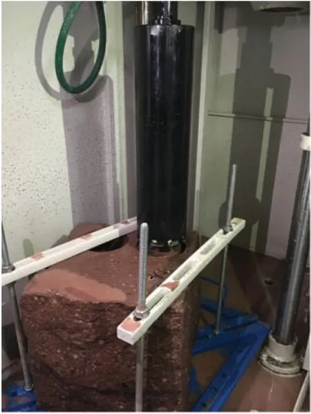
Figure 2:Sample processing preparation

Table 2:Physical and mechanical parameters of the rock specimens
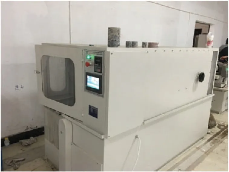
Figure 3:Self-developed rock and soil cutting and grinding machine
2.2 Basic Assumptions
According to one-dimensional wave theory, the engineering stress, strain, and strain rate of the specimen can be described as Eqs.(1)–(3)[11,19].


whereσ(t),ε(t)and(t),are the dynamic stress,strain,strain rate.AtandAs,are the cross sectional area of elastic rod and sample.εr(t),εf(t)andεt(t), are the strain values of incident, reflected and transmitted waves.
When these assumptions are satisfied, stress, strain, and strain rate can also be described as Eqs.(4)–(6)[19].

2.3 Testing Equipment
The tests were carried out on a triaxial dynamic impact mechanics testing system designed independently by the Zhejiang University of Science and Technology (Fig.4).The testing system is mainly composed of a triaxial thermal-hydraulic coupling system (Figs.5 and 6), a firing system,an incidence rod, a transmission rod, a data acquisition device, and a test analysis system.Among them,the bullet,incidence rod,and transmission rod are all cylindrical steel rods with a diameter of 100 mm and lengths of 600,5000,and 4000 mm,respectively.The main pressure valve of the triaxial and perimeter pressure power loading system is 0–60 MPa,the main pressure valve of the permeation hydrodynamic loading system is 0–45 MPa, and the main pressure valve of the temperature power loading system is-100°C to 100°C.The main function of the testing system is to simulate the dynamic compression and deformation characteristics of a geotechnical body under the coupling of multiple fields, such as ground stress, infiltration water pressure, and high and low temperatures in different deposition environments.
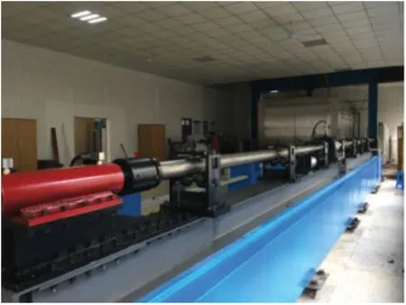
Figure 4:TDIMTS
The triaxial dynamic impact mechanics testing system includes five parts:loading drive system,pressure bar system,energy absorption system,signal acquisition system,and signal processing system.When the sample is correctly installed in the Thermal-hydraulic-mechanical triaxial coupling system,it is affected by axial pressure,confining pressure,osmotic water pressure and temperature.Since the axial pressure, confining pressure, osmotic water pressure and temperature are all static loads, the incident bar and transmission bar are essentially affected by one-dimensional stress and subject to one-dimensional stress wave theory.
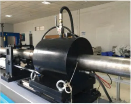
Figure 5:Thermal-hydraulic-mechanical triaxial coupling system
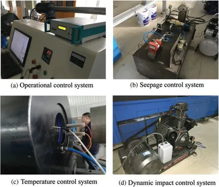
Figure 6:Key systems of the triaxial dynamic impact mechanics testing system
2.4 Test Program
The entire test was divided into 5 steps.Step 1 is the application of axial pressure, step 2 is the application of circumferential pressure, step 3 is the application of water pressure, step 4 is the application of warm pressure,and step 5 is the dynamic compression test.To reduce the effect of the friction between the specimen and the incidence and projection rods, grease was applied evenly to both ends of the specimen.The specimen was placed between the incidence and transmission rods,and the impact incidence energy was varied by adjusting the magnitude of the air pressure inside the storage chamber and the position of the bullet in the firing chamber.Li et al.[1] found that ancient underground cavern chambers are disturbed by blasting and quarrying to different degrees and at different scales in modern times, and Dai et al.[20] suggested that the destructive damage characteristics of blasting stress waves on rocks can be tested using the Split Hopkinson pressure bar(SHPB)method.Therefore,the impact incidence energy of this test was used to simulate blasting and quarrying disturbances.
Since the maximum thickness of the overlying strata of the ancient underground cavern in Shepandao is 30 m, the vertical principal stress was selected to calculate thein situstressvis 0.025Z according to the B-C-Haimson in-situ stress calculation method[21],where Z is the depth in meters.After the calculation,the vertical principal stress was 0.75 MPa.In order to facilitate the test operation,the ground stress was set to 1 MPa during the test.According to the depth-low temperature relationship curve of He et al.[22],the groundwater temperature was selected as normal temperature for the experimental design.
When exploring the effects of blasting quarry disturbance on the ancient underground cave chamber tuff,the number of serpentine rock samples collected was limited by the fact that Shepandao is a national geological mine park and the local tourism management department is concerned with the ecological protection of the ancient underground quarry.Thus,in order to control the number of specimens,a typical test protocol was selected for the study.Eight sets of tuff specimens were selected for the test,with a size ofφ96 mm×48 mm(Table 3).

Table 3:Selected typical testing scheme
During the test, a strain signal was generated during the propagation of the impact stress wave through the incident and transmission rods,and a pair of strain gauges were attached to the middle of the incident and transmission rods immediately adjacent to the triaxial thermal-hydraulic coupling system.The data were collected using an ultra-dynamic strain-gathering instrument.
2.5 Experimental Results
2.5.1 Time-Dynamic Stress Relationship
The time-dynamic stress curves of the tuff specimens under different impact air pressures are shown in Fig.7.
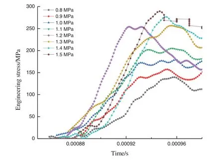
Figure 7:Time-stress curves for tuff under different impact pressures
As can be seen from Fig.7,when the tuff specimen began to generate stress,the stress increased with increasing impact air pressure.The tuff stress in scenario 1 was the smallest, the stress in scenario 8 was the largest, and the stress in scenario 8 was 1.97 times that in scenario 1.The time it took to generate the stress was 0.00086 s,and the stress started to decrease at 0.00095 s.Then,it tended to level off.
2.5.2 Time-Strain Relationship
The time-strain curves of the tuff specimens under different impact air pressures are shown in Fig.8.
As can be seen from Fig.8,the strain range of the tuff specimens increased linearly from 0 to 0.04 with increasing time from 0.000855 to 0.0011 s.At impact air pressures of less than 1.1 MPa,the strain range was 0.04 to 0.05,totaling 50%.The strain growth of the tuff tended to slow down after 0.0011 s.
It can also be seen from Fig.8 that the peak strain was greatest when the tuff was subjected to an impact air pressure of 1.1 MPa,indicating that the tuff was already damaged.As the tuff complies with Hooke’s law,since the peak stress in the tuff was around 285 MPa,σwas constant,and the Poisson’s ratio of the tuff was constant,which indicates that the dynamic modulus of the elasticity of the tuff changed during the dynamic test.
2.5.3 Dynamic Stress-Strain Relationship
The stress-strain curves of the tuff specimens under different impact air pressures are shown in Fig.9.
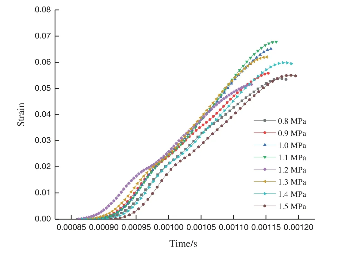
Figure 8:Time-strain curves for tuff under different impact pressures
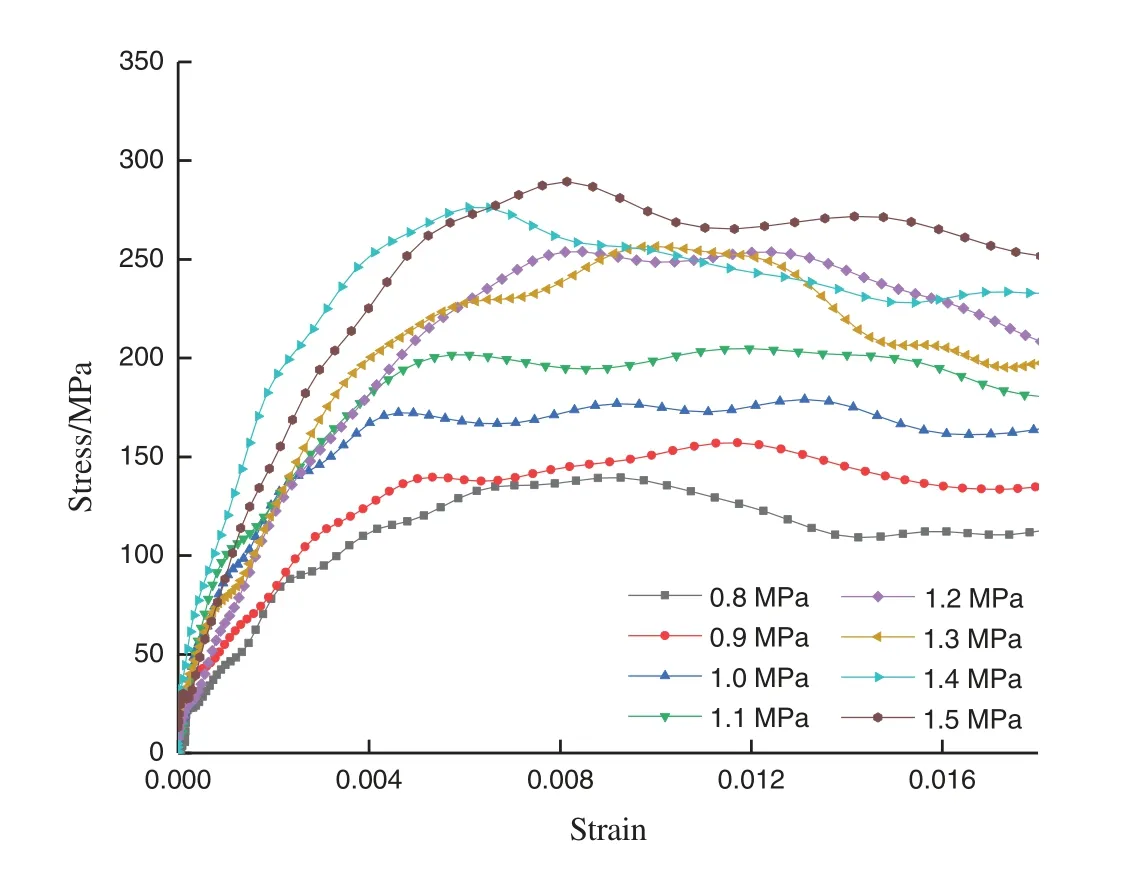
Figure 9:Stress-strain curves for tuff under different impact pressures
As can be seen from Fig.9, the peak stress and peak strain of the tuff specimens increased with increasing impact air pressure.When the axial and circumferential pressures were 1 MPa,the permeated water pressure was 1 MPa, the temperature was 25°C, and the impact air pressure reached 1.5 MPa, the peak stress in scenario 8 was the largest (275.07 MPa), and the peak strain was 0.0081.When the axial and circumferential pressures were 1 MPa,the permeated water pressure was 1 MPa, the temperature was 25°C, and the impact air pressure reached 0.8 MPa, the peak stress in scenario 1 was the smallest (139.08 MPa).When the axial and circumferential pressures were 1 MPa, the permeated water pressure was 1 MPa, the temperature was 25°, and the impact air pressure reached 0.8 MPa, the peak stress in scenario 1 was the smallest (139.44 MPa), and the peak strain was 0.0056.The peak stress and peak strain in scenario 8 were 1.97 and 1.45 times those in scenario 1, respectively.This indicates that the impact compression damage process of the tuff at different impact air pressures has obvious stages,and the dynamic stress-strain curve of the rock can be roughly divided into three stages:a non-linear compression-density stage,an elastic deformation stage,and an unloading stage.The tuff exhibited the characteristics of the non-linear compression-density stage in the early stage of loading,followed by the elastic deformation stage with linear growth,and it gradually exhibited the characteristics of the plastic deformation stage in the middle stage of loading.The peak stress and peak strain of the tuff increased as the impulsive air pressure increased,and when the peak strength was reached,the stress decreased,exhibiting an unloading phase.
During the non-linear compression phase, the stress-strain curve curved upwards.The microcracks and pores in the rock were squeezed,the pores and holes shrank,and the cracks closed,resulting in the tuff being squeezed tighter and tighter.The stress-strain in the elastic deformation phase was proportional,with stress concentrations or shear deformations occurring at microdefects in the rock,resulting in further crack development.The peak stress in the tuff specimen in the unloading phase decreased rapidly,and the large number of microcracks in the rock expanded and caused damage.
2.5.4 Energy Dissipation Analysis
The time-strain energy relationship of the tuff specimens under different impact air pressures is shown in Fig.10.Strain energy of tuff under different impact pressure is shown in Fig.11.
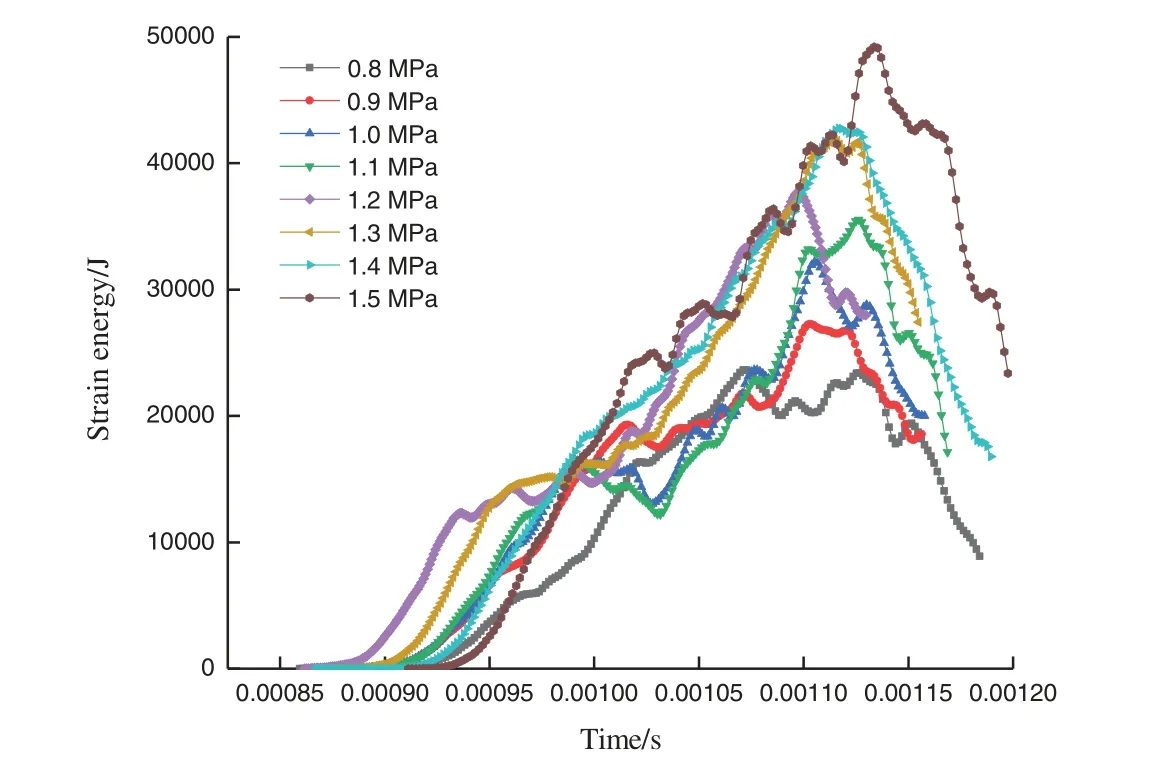
Figure 10:Time-strain energy curves for tuff under different impact pressures
As can be seen from Fig.10, the strain energy of the tuff gradually increased as the impact air pressure increased.When the axial and circumferential pressures were 1 MPa, the permeated water pressure was 1 MPa,the temperature was 25°C,and the impact air pressure reached 1.5 MPa,the corresponding strain energy was the largest at 0.001135 s in scenario 8, i.e., 49210.74 J.When the axial and circumferential pressures were 1 MPa, the permeated water pressure was 1 MPa, the temperature was 25°C,and the impact air pressure reached 0.8 MPa,the corresponding strain energy in scenario 1 was the maximum at 0.001071 s,i.e.,23,641.14 J.The strain energy in scenario 8 was 2.08 times that in scenario 1.
It can also be seen from Fig.10 that the energy required to rupture the tuff in the ancient underground cavern was small when the local stress, groundwater pressure, temperature, and quarrying disturbance were all small; however, as the quarrying disturbance increased, the degree of damage to the tuff specimen increased, resulting in the energy required to rupture the tuff also increasing, indicating that more energy input and higher stress levels will inevitably result in the tuff specimen breaking more fully, which is largely consistent with the findings of Yang et al.[10](The results show that the dynamic mechanical properties and energy dissipation laws of composite rock mass have obvious strain rate effect).Therefore, the development and conservation of ancient underground cave chambers should pay sufficient attention to the unloading effect because tourism development,which drains the groundwater in ancient underground caves,causes the overall balance of the groundwater level and seepage patterns in the original chambers and the surrounding strata to be broken,resulting in stress redistribution in order to release energy.
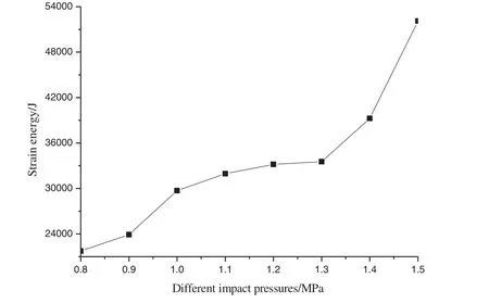
Figure 11:Strain energy of tuff under different impact pressure
As can be seen from Fig.11, since the bullet impact direction is the same as the horizontal lamination direction of the tuff,the degree of damage to the tuff specimens increased with increasing strain energy.Compared to the strain energy of the tuff specimens under an impacting air pressure of 0.8 MPa, the average strain energies under stresses of 0.9, 1.0, 1.1, 1.2, 1.3, 1.4, and 1.5 MPa were 9.91%, 36.58%, 46.92%, 52.52%, 54.19%, 80.49%, and 139.53% higher, respectively.The tuff specimen in scenario 1(Impact pressure 0.8 MPa)was only slightly damaged,with an obvious crack generated in the middle of the specimen’s surface,and the strain energy was smaller.The tuff specimen in scenario 3 (Impact pressure 1.0 MPa) generated a more obvious shear surface at 45° on the right side of the surface,at which time the strain energy increased accordingly.The tuff specimen in scenario 8(Impact pressure 1.5 MPa)experienced the greatest degree of damage and exhibited a core-retention type block fragmentation.The strain energy increased significantly,transferring the energy formed by the impact of the compression bar to the tuff specimen,resulting in the formation and development of microcracks within the specimen,which led to its rupture.This is because the horizontal laminated tuff specimens were loaded parallel to the laminae,and the microcracks and pores within the specimen were less likely to expand along the laminae when stressed.Therefore,the degree of damage to the tuff specimens exhibited an asymptotic growth pattern with increasing strain energy, which is generally consistent with the findings of Ping et al.[23](The results show that the proportion of absorbed energy and incident energy is relatively constant, and absorbed energy increases with the incident energy growing).This indicates that as the strain energy to which the tuff specimens was subjected increased,the degree of tuff fracturing became more intense,and the average fragmentation size decreased with increasing strain energy.
2.5.5 Absorption Energy vs.Peak Strain
Under the action of different impact air pressures, the deformation of the tuff specimens was related to the transfer of energy,and the curve of the absorbed energy versus the peak strain and the fitted curve are shown in Fig.12.
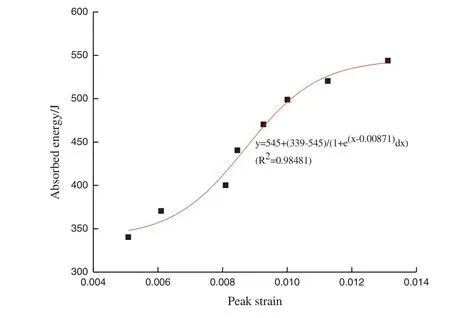
Figure 12:Peak strain-absorbed energy for tuff under different impact pressures
As can be seen from Fig.12,as the peak strain increased,the energy absorbed by the tuff specimen exhibited a growth trend.The absorbed energy in the peak strain range of 0.008–0.012 accounted for 62.5%.When the peak strain is greater than 0.012, the growth of the energy absorbed by the tuff specimen tended to slow down,indicating that the tuff specimen was close to destruction.The higher the peak strain of the tuff was, the more cracks it contained, and the required absorbed energy was higher.
3 Numerical Simulation
3.1 HJC Model
The material model for TDIMTS numerical simulation is virtually associated with the dynamic behavior of rocks under impact loading.The dynamic mechanical behavior of brittle materials such as concrete and rocks,in most case,could be described by the HJC model,Riedel-Hiermaier-Thoma(RHT) model, Taylor-Chen-Kuszmaul (TCK) model, continuous smooth cap (CSC) model and the Karagozian-Case(K-C)model[24,25].Moreover,Cardu et al.[24,26]utilized the Blast Damage Index(BDI)criterion to evaluate the stability of a rock slope under blasting.For LS-DYNA 3D,the HJC model is considered to be applicable to rock and concrete materials under large deformation and high strain rate[24–28].In this work,the HJC model as the damage model of impact loading is employed to describe the dynamic behavior of rock masses.The damage model HJC focuses more on interactions and heterogeneity than the traditional elastic and fracture models [24,29].It can well interpret the dynamic responses of rocks under impact loading and the results obtained using the HJC model agreed well with that of laboratory investigations[24,29].For HJC model,the evolution of stressvs.strain can be described as Eq.(7).The yield surface is illustrated in Fig.13a[24,28].

whereσ*=σ/fc,σrepresents the stress,fcis the uniaxial compressive strength under static loading,Adenotes the normalized cohesion strength,Dis the damage factor,Bindicates the dimensionless pressure hardening coefficient, dimensionless pressureP*=P/fc,Prepresents the actual pressure,Cdenotes the strain rate coefficient,Nrefers to the pressure hardening index,the dimensionless strain rateis the actual strain rate andis the reference strain rate.
The damage factorD(0 ≤D≤1)is defined as the sum of the equivalent plastic strain and plastic volumetric strain,as shown in Eq.(8)and Fig.13b[24].

whereΔεpis the increment of equivalent plastic strain,Δμpdenotes the increment of plastic volumetric strain,εfp+μfp=D1(P*+T*)D2 =f(P)≥EFMINwhich represents the plastic strain when the material is finally fractured at constant pressureP.The parameterEFMINis the amount of plastic strain before fracture.D1andD2are the damage constants,respectively.
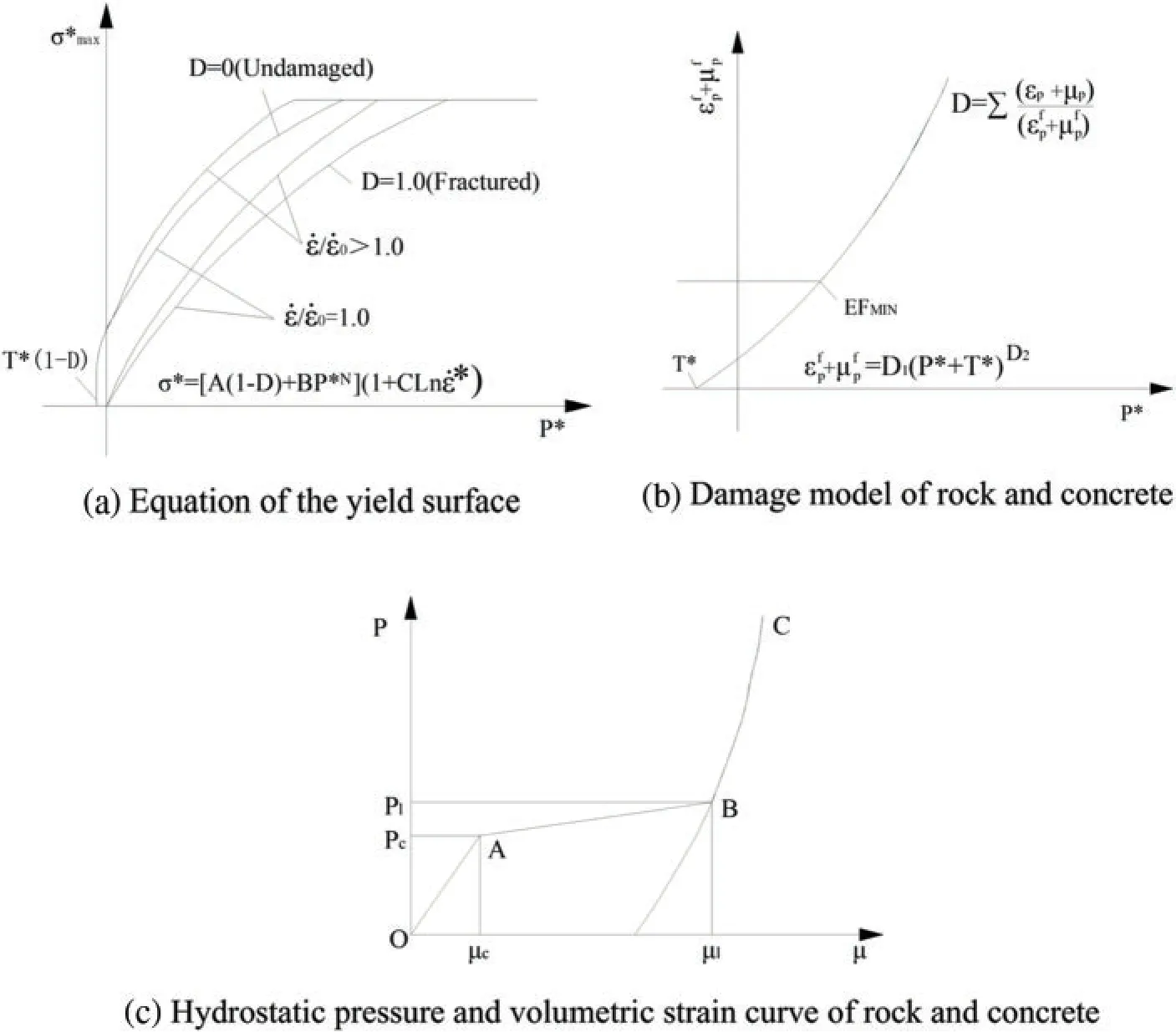
Figure 13:Original HJC model[24,28]
The relationship between the hydrostatic pressure and the volumetric strain of the rock and concrete is expressed by the segmental state equation shown in Fig.13c[24].Stage OA describes the linear elastic stage whenp <pc,and both the loading section and unloading section can be described as Eq.(9)[24].

whereKeis the bulk modulus,pcandμcare the crushing pressure and crushing volumetric strain in the uniaxial compressive experiment,respectively.
Stage AB is a plastic transition stage during whichpc≤p <pl,and plastic deformation occurs as the voids of concrete are compressed[24].
Loading section can be described as Eq.(10).

whereplis the locking pressure,andμlis the locking volumetric strain.
Unloading section can be described as Eqs.(11)and(12).

whereKlis the plastic volumetric modulus,pmaxandμmaxare the maximum volumetric pressure and volumetric strain before unloading in which the holes of the concrete and rock are expelled and damage occurs accompanied by cracks.
Stage BC is a fully compacted stage during whichp >pl,when the pressure reachespl,the holes are crushed completely.The relationship betweenpandμis represented by a cubic polynomial[24].
Loading section can be described as Eqs.(13)and(14).

Unloading section can be described as Eq.(15).

The material parameters for the HJC model are determined on the basis of previous research[24–29]and site geology for the studied ancient underground rock mass.Table 4 presents the properties of the rock masses.

Table 4:Properties of rock masses for the HJC model
3.2 Finite Element Modeling
3.2.1 Modeling and Meshing
Three-dimensional solid element of SOLID 164 was selected for the modeling unit in ANSYS/LSDYNA software.In order to simulate the actual test situation,a full model is adopted for modeling.The finite element model components included sample, incident bar, and transmission bar (see Fig.14).The sample length was 50 mm, the incident bar length was 5000 mm, the transmission bar length was 4000 mm,and all the diameters were 100 mm.The bullet is simulated by the actual loaded dynamic pressure.The incident bar and the transmission bar used the same elastic material,which had an elastic modulus of 210 GPa,a density of 7.8 g/cm3,and a compressional wave velocity of 5100 m/s.

Figure 14:Finite element modeling
Considering the model accuracy and computational efficiency, the proposed model adopts the mapping grid partitioning method.The unstructured grids are generated using the HYPERMESH software.The cell size depends on the element size and related density.Mesh smoothing is performed by an auto-mesh smoothing algorithm[24].The mesh size was 5 mm for incident bar,the transmission bar and the sample.The incident bar is divided into 380,000 units.The transmission bar is divided into 303,200 units.The rock sample is divided into 3790 units.
3.2.2 Contact Select
Contact type of*CONTACT_AUTOMATIC_SURFACE_TO_SURFACE in LS-DYNA is used for the contact between the incident bar,transmission bar and the sample.It is very important to select the main and secondary surfaces of rock samples,incident and transmission rods.The friction between the sample and the pressure bar is ignored.The setting of the contact surface is shown in Fig.15.
3.2.3 Load Application
In order to simulate the dynamic impact of bullet, the measured incident stress pulse is directly applied to the end of the incident bar(see Fig.16).The load applied to simulate bullet impact force is mainly realized in HYPERMESH software.It is completed by using PRESSURE function in module ANALYSIS.Earth stress, groundwater pressure, temperature are realized by applying pressure and temperature field around the rock sample, respectively (see Fig.17).These loads are assigned by PRESSURE and TEMPERATURES function in module ANALYSIS,which are applied to the outer surface of the sample.
3.2.4 Erosion Algorithm
As the fracturing of rocks differs from that of the joints, the erosion algorithm which allows several fracture criteria to be predefined in the modeling is employed to determine the fracturing processes of different materials[24–29].It is difficult to track the crack propagation process in dynamic impact test.In this investigation,the failure criterion of maximum principal strain is utilized with the Erosion algorithm.The whole process of dynamic fracture is tracked by the numerical simulation algorithm.During numerical simulation,the element will be invalid and thus be killed by the code of LS-DYNA3D if the calculated stress or strain state of the element meets the failure criterion predefined by the Erosion algorithm[24].
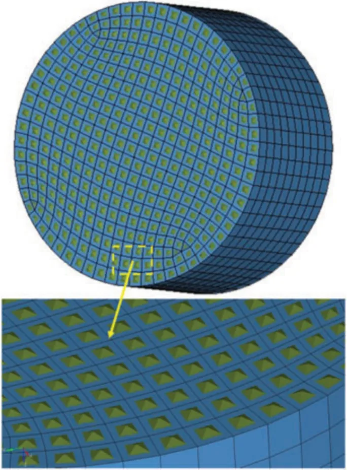
Figure 15:Setting of contact surface
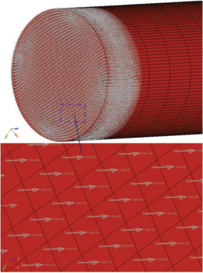
Figure 16:Impact pressure load of the incident bar
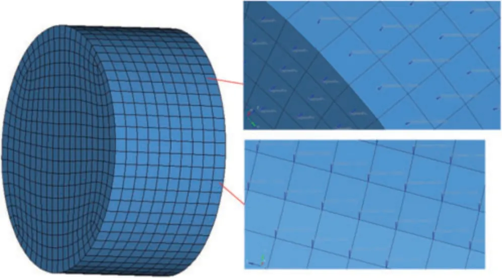
Figure 17:Earth stress,groundwater pressure and temperature load on sample
3.3 Dynamic Failure Process of Sample
The evolution process of peak stress of samples under different impact pressures is shown in Fig.18.The comparison between the numerical simulation results and the experimental results of peak stress is shown in Fig.19.As shown in Figs.18 and 19, the peak stress value of numerical simulation is in good agreement with the results of dynamic impact test.It shows that the numerical model established in this study can be used to simulate the dynamic mechanical properties of different rocks under higher impact pressures.
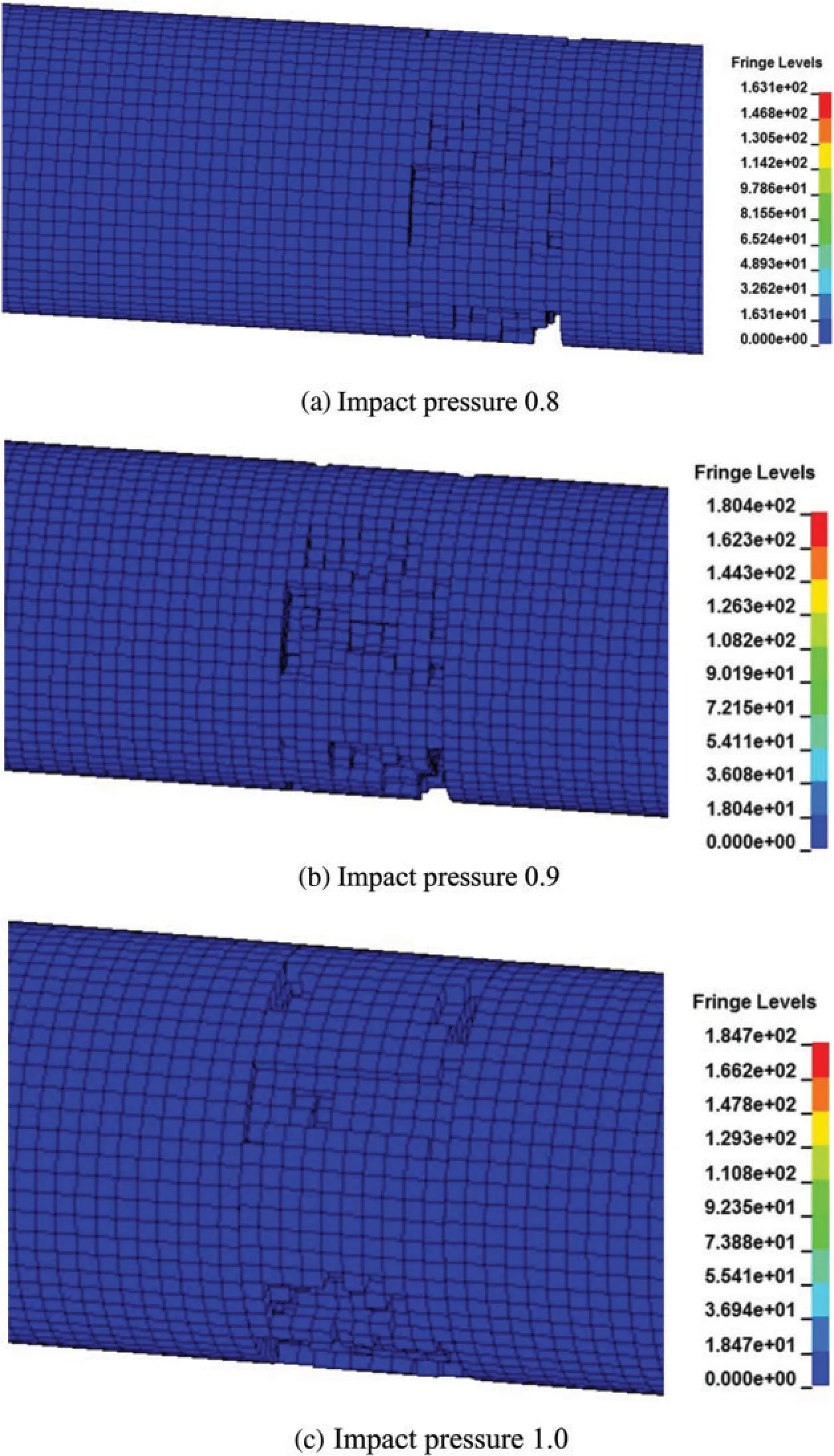
Figure 18:(Continued)
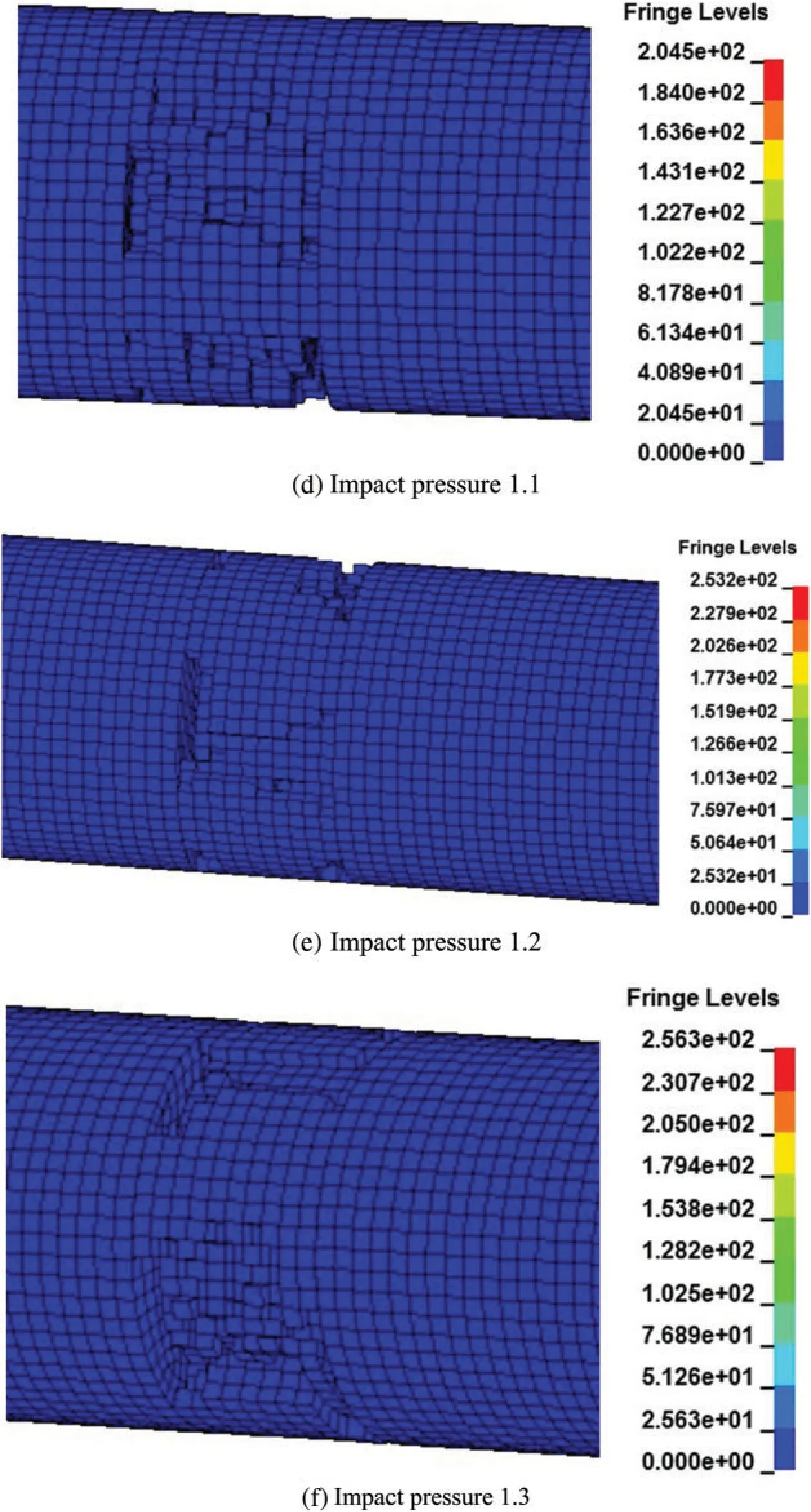
Figure 18:(Continued)
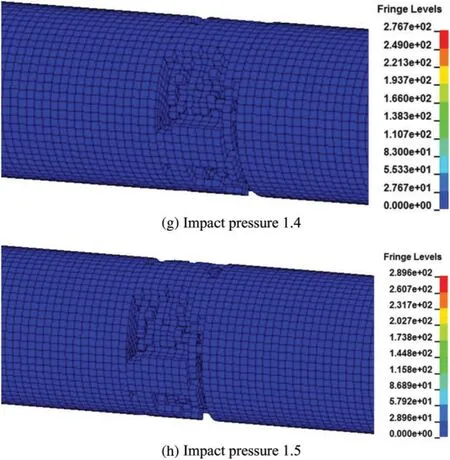
Figure 18:Evolution process of stress of samples under different impact pressures
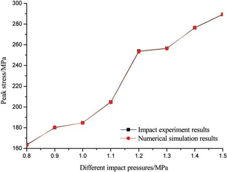
Figure 19:Comparison between the numerical simulation results and the experimental results of peak stress
3.4 Failure Pattern of Sample
Comparison of failure patterns of samples under different impact pressures is shown in Fig.20.As shown in Fig.20,the transformation mode of sample failure pattern has a high similarity with the test results.According to the comparison of failure patterns of rock mass,the failure degree of samples increases with the increase of strain rate.
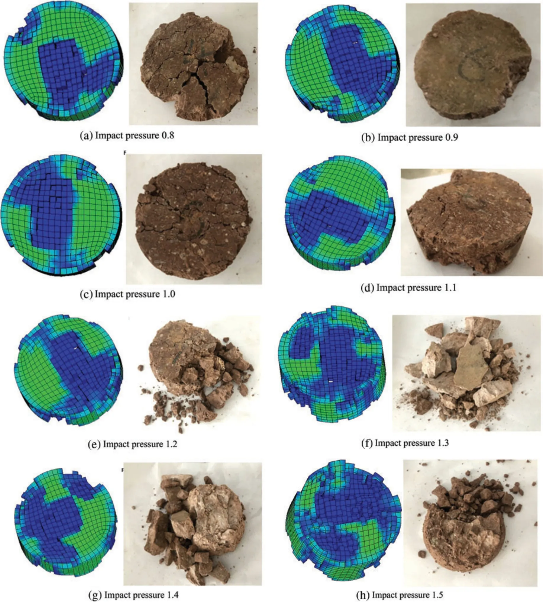
Figure 20:Comparison of failure patterns of samples under different impact pressures
4 Conclusions
The dynamic characteristics of the tuff collected from an ancient quarry in Shepan Island,Zhejiang Province,were studied using a TDIMTS,and the main conclusions are as follows:
(1) Under the same local stress, groundwater pressure, and temperature, the damage to the tuff specimen caused by blasting and quarrying disturbances gradually increased with increasing impact air pressure.
(2) Under the same local stress, groundwater pressure, and temperature, the energy required to rupture the tuff from the ancient underground chamber was small when the impact air pressure was relatively low;however,the damage to the tuff specimens from the quarrying disturbance gradually increased with increasing of the impact air pressure.
(3) Finally,the degree of damage to the tuff specimen and the strain energy exhibited asymptotic growth.When under high strain energy, the degree of rupturing of the tuff was much more serious than that under low strain energy, and the average crushing size decreased with increasing of the strain energy.
(4) The TDIMTS experiment on tuff specimen under thermal-hydraulic-mechanical coupling was simulated using the HJC model and LS-DYNA software.The dynamic failure process,failure pattern and peak stress of tuff specimen were calculated,and the simulation results were proven to be reliable.By comparing the simulation results with the experimental results,it was found that the HJC model reflected the dynamic impact performance of tuff specimen, and the simulation results showed an evident strain rate effect.
Funding Statement:The financial supports for this research project by the National Natural Science Foundation of China (No.41602308).This research was supported by Zhejiang Provincial Natural Science Foundation of China under Grant No.LY20E080005.
Conflicts of Interest:The authors declare that they have no conflicts of interest to report regarding the present study.
 Computer Modeling In Engineering&Sciences2023年1期
- Computer Modeling In Engineering&Sciences的其它文章
- A Fixed-Point Iterative Method for Discrete Tomography Reconstruction Based on Intelligent Optimization
- A Novel SE-CNN Attention Architecture for sEMG-Based Hand Gesture Recognition
- Analytical Models of Concrete Fatigue:A State-of-the-Art Review
- A Review of the Current Task Offloading Algorithms,Strategies and Approach in Edge Computing Systems
- Machine Learning Techniques for Intrusion Detection Systems in SDN-Recent Advances,Challenges and Future Directions
- Cooperative Angles-Only Relative Navigation Algorithm for Multi-Spacecraft Formation in Close-Range
