Spin current in a spinor Bose–Einstein condensate induced by a gradient magnetic field
Li Tian(田丽) Ningxuan Zheng(郑宁宣) Jun Jian(蹇君) Wenliang Liu(刘文良)Jizhou Wu(武寄洲) Yuqing Li(李玉清) Yongming Fu(付永明) Peng Li(李鹏)Vladimir Sovkov Jie Ma(马杰) Liantuan Xiao(肖连团) and Suotang Jia(贾锁堂)
1State Key Laboratory of Quantum Optics and Quantum Optics Devices,Institute of Laser Spectroscopy,Shanxi University,Taiyuan 030006,China
2Collaborative Innovation Center of Extreme Optics,Shanxi University,Taiyuan 030006,China
3School of Science,Key Laboratory of High Performance Scientific Computation,Xihua University,Chengdu 610039,China
4St. Petersburg State University,7/9 Universitetskaya nab.,St. Petersburg 199034,Russia
We develop a research of spin currents in a23Na spinor Bose–Einstein condensate(BEC)by applying a magnetic field gradient. The spin current is successfully induced by the spin-dependent force arising from the magnetic field gradient. The dynamics of the spin components under the magnetic force is investigated.The study is promising to be extended to produce a longer spin-coherence and to enhance the sensitivity of the spin-mixing interferometry in a spinor BEC.
Keywords: spinor Bose–Einstein condensate,spin current
1. Introduction
Neutral atom gas Bose–Einstein condensates (BECs)have made new achievements to the field of condensed matter physics.[1–3]They provide highly controllable platforms for simulating and exploring many condensated matter phenomena. In this respect, research of spintronics[4]is of particular interest. Spin current is a key ingredient in the spintronics.
Spin currents were generated using exciton-polaritons and excitons[5,6]in a magnetic insulator. In ultracold atomic gases,[7]the spin segregation and the spin Hall effect were demonstrated in Refs. [8–11] Experimental phenomena related to the spin currents have also been observed in ultra-cold Bose gases and Fermi gases.[12,13]The spin current generation and relaxation were studied in a quenched spin–orbit-coupled BEC.[14]The quantum bang-bang technique was employed to control spin currents in a Bose gas.[15]Spin-current-induced phenomena can also be largely suppressed by the bang-bang control consisting of periodically appliedπpulses.[16]The spin current is a source of dephasing in applications of the spin-mixing interferometry,[17]which can be directly applied to techniques of the AC magnetometry and spectrum analyzers of the environment.[6,18]In the cold atom systems,a magnetic field is hardly stabilized and eliminated.[19,20]The force on the spin components produced by the magnetic field gradient will induce the spin current.[16]The relating properties need to be further researched.
In this work,we investigate properties of spin currents in a23Na spin-1 BEC by applying a magnetic field gradient to the BEC in thez(vertical)direction. We record the position of the spin component versus varying holding time,and observe the travel distance with the fixed holding time under different magnetic field gradients: the relative travel positionzfor spinmF=0 keeps unchanged, while the travel distance between the data for spinmF=±1 depends linearly on the magnetic field. These results pave the way for research and control of spin current in the future.[21]
2. Experimental setup
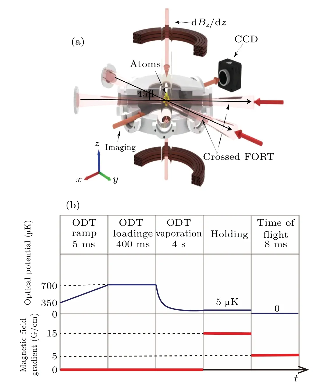
The setup is shown in Fig. 1(a). The details of the experiment are similar to our previous work.[22,23]The thermal sodium flux was slowed down by a Zeeman slower and entered to the science chamber,[24]in which the laser and evaporation cooling as well as the spin current were carried out. The viewports of the scientific chamber were used for the magnetooptical-trap(MOT)beams and the dipole trapping beams. The gradient magnetic field,generated by a pair of anti-Helmholtz coils as shown in Fig. 1(a), would kick the atoms and separate the spin components. The cross angle of the two dipole trap laser beams was 45°. The dipole trap laser beams were focused by two lenses with the focal distancef=300 mm.The beam waists of the dipole traps 1 and 2 were~41 μm and~35 μm measured using the parametric heating method under a high dipole trap laser power of 14 W.[25]The number of atoms loaded into the optical dipole trap was about 106.Forced evaporation cooling was accomplished by reducing the potential of the dipole trap. The potential was exponentially reduced within 4 s as shown in Fig. 1(b). The evaporation timet, the time constant and the final dipole trap laser power were optimized during the force evaporation. After 4 s force evaporation in the dipole trap,the optical potential was as deep as-5 μK.The number of the sodium BEC atoms in theF=1 state was 1.2×10⁵,and the temperature was about 56 nK.In the experiment,the relative positions of spin components were recorded by the horizonal absorption imaging CCD shown in Fig.1(a). As the spin current is induced by the gradient magnetic field along thezdirection. Figure 1(b) shows the time sequence to induce and research the spin current. BEC was held in the dipole trap after force evaporation, the magnetic field gradient was then switched on to induce the spin current.The relative travel positions of spin components were recorded by Stern–Gerlach (S-G)measurement followed by 8 ms time of flight.

Fig.1. (a)Schematic illustration of the experimental setup. The waists and the powers of the dipole trap beam 1 (beam 2) are ~41 μm(~35 μm) and ~70 mW (~60 mW). The crossing angle between the dipole trap beams is θ =45°. The number of the spinor BEC atoms is 1.2×10⁵, and the temperature of the BEC is 56 nK. The magnetic field gradient dBz/dz is generated by the anti-Helmholtz coils, its direction is shown by the arrow. (b) Time sequence for research of the spin current induced by the magnetic filed gradient.
The gradient field along the vertical directionz(shown in Fig.1(a))ranged from 10 G/cm to 30 G/cm. Spin currents were then generated by application of a magnetic field gradient along thezdirection, the sequence is shown in Fig. 1(b).The magnetic field gradient was switched on at the end of the force evaporation. The BEC was held in the dipole trap. After a variable holding time,the BEC was released from the far offresonance optical dipole trap(FORT).Three spin components of the sodiumF=1 spinor BEC were spatially separated by an S-G absorption imaging. In order to confirm the generation of the spin current,we record the relative positionszfor everymF.
3. Results and discussion
We set the magnetic field gradient to be 15 G/cm and recorded the travel position of the three spin components under the varying holding time. Figure 2 shows three typical OD images under different holding times for spinmF=±1,0 components of the sodiumF=1 BEC. The position of the three components with the zero holding time [Fig. 2(a)] was set as the reference. Figure 2(b)shows that positionszfor spinmF=±1 move in the opposite directions,the relative positionzformF=0 keeps unchanged in comparison to Fig.2(a). Figure 2(c)gives the absorption image with 170 ms holding time,and we find that the relative positions along thezdirection for all three components are almost the same as in Fig.2(a).

Fig.2.Typical absorption images of condensates(a)with the zero holding time set as the reference,and with different holding times:(b)15 ms and(c)170 ms. Dashed lines indicate the relative positions of the spin components under the different holding times.
The result shown in Fig.2 indicates that the spin current is successfully induced by the spin-dependent force arising from the magnetic field gradient. The spin-dependent force applied to the atoms determines the position and the motion direction of each component, the stray magnetic field gradient in the horizontal plane makes positionszfor the two spins(mF=±1)move in the vertical direction.

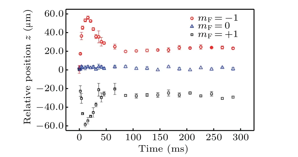
Fig.3. Time dependence of the relative positions z for spins mF =±1 and mF=0 under the 20 G/cm magnetic field gradient. The position z with the zero holding time is assumed to be zero.
Figure 3 shows the relative positions of the spin components under variable holding times. We can find that when the holding time is under 15 ms, the difference Δzbetween a pair of positions formF=±1 increases gradually, and then decreases. The time turning points for the maximum position mainly depend on the oscillation of the magnetic field gradient. After 50 ms,the spin components nearly return to the initial positions and remain unchanged afterwards. These results are in agreement with the theoretical predictions of Ref.[16].

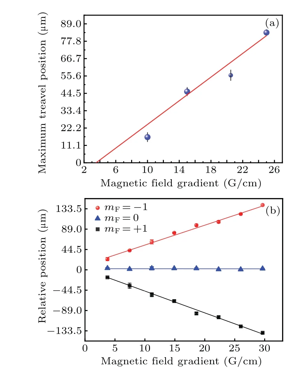
Fig.4. (a)The maximum travel position for spin mF=-1 vs. the magnetic field gradient.The circles indicate the experimental results and the line is the linear fit. (b)The travel distances with the fixed holding time of 35 ms vs. the magnetic field gradient,in the experimental points and the linear fits.
Finally,we recorded the travel distance for the three components by changing the electric current in the anti-Helmholtz coil from 10 A to 60 A, corresponding to the magnetic field gradient from 5 G/cm to 30 G/cm,with the fixed holding time of 35 ms. The result is shown in Fig. 4(b). As the anti-Helmholtz-coil electric current increases,the difference Δzbetween a pair of positions formF=±1 increases linearly in the opposite directions,and the positionzof themF=0 curve does not change. The lines are the linear fits.
4. Conclusions
In summary,the spin current is generated by the magnetic field gradient. The generation of the spin current is researched by recording the relative position of eachmFcomponent. We record the travel positions of the three spin components under a variable holding time. We also record the travel distance with a fixed holding time under different magnetic field gradients. The positionzfor spinmF=0 does not change with the magnetic field. The difference Δzbetween a pair of positions formF=±1 increases gradually with the increase of the electromagnet current. In the present work focused on manipulation of spin currents by recording the dynamic of spin components under different magnetic field gradients, we find that spin current has a fast response to the change of magnetic field gradient and we hope to better apply spin current in the field of ultra-cold atomic gas in the future, for example, the application of the fast control technique to spin current.
Acknowledgements
Project supported by the National Key R&D Program of China (Grant No. 2017YFA0304203), the National Natural Science Foundation of China (Grant Nos. 62020106014, 62175140, 61901249, 92165106,12104276, and 62011530047), PCSIRT (Grant No. IRT-17R70), the Educational Reform and Innovation Project of Higher Education in Shanxi Province, China (Grant Nos. Z20220001 and Z20220013), 111 Project (Grant No.D18001), the Applied Basic Research Project of Shanxi Province(Grant Nos.201901D211191 and 201901D211188),and the Shanxi 1331 KSC.
- Chinese Physics B的其它文章
- A design of resonant cavity with an improved coupling-adjusting mechanism for the W-band EPR spectrometer
- Photoreflectance system based on vacuum ultraviolet laser at 177.3 nm
- Topological photonic states in gyromagnetic photonic crystals:Physics,properties,and applications
- Structure of continuous matrix product operator for transverse field Ising model: An analytic and numerical study
- Riemann–Hilbert approach and N double-pole solutions for a nonlinear Schr¨odinger-type equation
- Diffusion dynamics in branched spherical structure

