
Application and Research of High-Power Electric Servo System on Launch Vehicle
2022-10-29 00:49:42FENGWeiCUIYebingWANGYaoyaoYUGeSONGShuweiCHENShuhengGUDawei
Aerospace China 2022年2期
FENG Wei ,CUI Yebing ,WANG Yaoyao ,YU Ge ,SONG Shuwei ,CHEN Shuheng ,GU Dawei
1 Shanghai Institute of Spaceflight Control Technology,Shanghai 201109
2 Shanghai Engineering Research Center of Servo System,Shanghai 20110
Abstract: The 30 kW high-power electric servo system used in the solid booster of the Long March 6A (LM-6A)launch vehicle is introduced,and the function,composition of the system as well as its constituent equipments are detailed.To solve the problem of out-of-tolerance in the system dynamic characteristics,an advanced correction network algorithm architecture and double notch filter were designed.Experimental verification was conducted to prove that the dynamic characteristics requirement under multiple operating conditions could be met.
Key words: electric servo system,servo control driver,electric servo mechanism,power drive module,advanced correction link,notch filter
1 INTRODUCTION
The electric servo system is a position-following system with a servo motor as the control element.It performs closed-loop control through position feedback,realizes the transformation of electrical energy into mechanical energy,and drives the load(engine jet pipe,rudder surface,etc.) to move according to the given command.
The electric servo system is composed of a servo control driver,a servo motor,a transmission mechanism,a position detection device,etc.Its composition is shown in the block diagram in Figure 1.
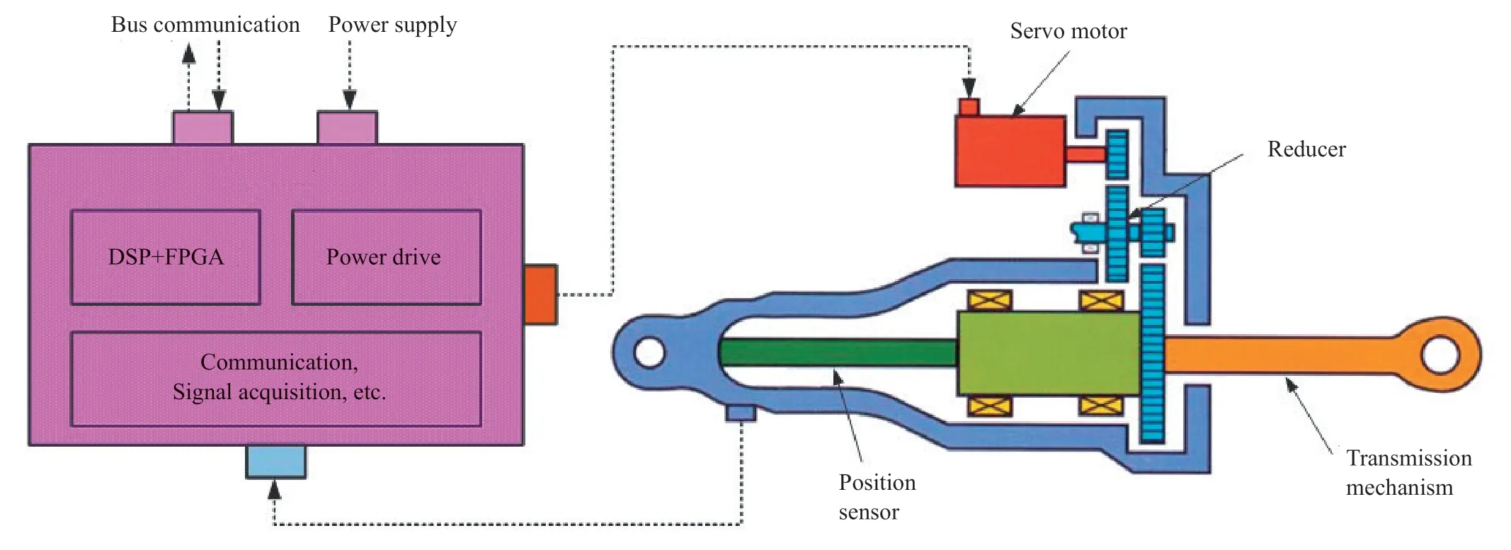
Figure 1 Schematic diagram of typical servo system
Compared with an electro-hydraulic servo system,an electric servo system has the following advantages:
1) Simple structure,low development cost and high reliability;
2) Clean energy source (electricity),convenient to use;
3) No long-standing problems such as locked rotor and oil leakage;
4) Less supporting equipment and facilities,convenient for testing and maintenance.
With the above advantages,the electric servo system can better meet the needs of rapid maneuvering,high-density launch of the space transporters,its application in the field of space transportation is becoming more and more common.
The low-power rotary electric servo system used in the Long March 6 carrier rocket (LM-6) was the first engineering application of electric servo technology in the domestic transportation field.Subsequently,electric servo systems of different power levels such as 5 kW,10 kW,20 kW,and 30 kW were successively applied to the launch vehicles.The maiden flight of the LM-6A launch vehicle on March 29,2022 was a complete success,realizing the first application of an electric servo system with a power level of 30 kW,and it is also the most powerful electric servo product used in the launch vehicles of China.
2 HIGH POWER ELECTRIC SERVO SYSTEM FOR LM-6A
The LM-6A launch vehicle is China’s first solid-liquid bundled rocket.It uses four solid boosters,where each booster adopts a high-power electric servo system to realize the two-way swing of the flexible nozzle.The rocket adopted the servo system with online fault diagnosis and the adaptive reconstruction technology for the first time in China.Compared with low-power servo systems,the high-power electric servo systems need to consider the influence of high voltage and large current,the suppression of strong electromagnetic interference,and the realization of high-thrust servo mechanisms from the initial design.The finished product can provide high-precision and high-stability thrust for the rocket during flight,where the thrust can reach 70000 N.The maximum output power of a single electric servo mechanism reaches 30 kW.The actual products are shown in Figure 2.
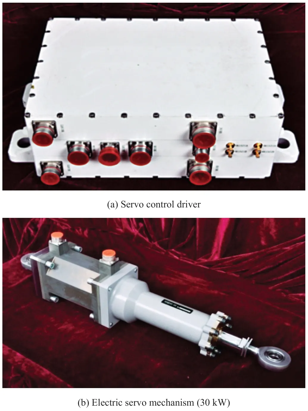
Figure 2 Electric servo products for LM-6A
2.1 Servo Control Driver
A single servo control driver consists of a digital control module and two power drive modules,and is capable of driving two electric servo mechanisms.The servo control driver structure adopts three-layer stacking,the middle layer is the digital control module,and the upper and lower layers correspond to the power drive modules of the two servo mechanisms respectively.
The schematic block diagram of the servo control driver is shown in Figure 3.The digital control module adopts the system architecture of a dual motor control unit (MCU),which is composed of a digital signal processing (DSP) chip and a field programmable gate array (FPGA) chip,the DSP enables the control algorithm,the FPGA and two bus protocol chips provide the dual redundant communication function of the 1553B bus,while the FPGA completes the acquisition and processing of signals such as position feedback,motor current,and voltage.
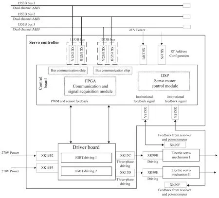
Figure 3 Schematic diagram of servo control driver
The power supply adopts 270 V high-voltage lithium battery,and the power drive module adopts 600 V/600 A Insulated Gate Bipolar Transistor (IGBT) half-bridge driver chip.The three half-bridge chips constitute the three-phase fullbridge power driver circuit to realize the drive control of the servo motor.A high-power active clamp circuit,measures and suppresses peak voltage within the hardware circuit to realize over voltage protection of the power drive circuit.In addition,dead zone setting is based on Pulse Width Modulation (PWM),enabling PWM interlocking of upper and lower bridge arms of an IGBT,and overcurrent control software was adopted.The protection algorithm realizes the overcurrent protection of the power drive circuit.In order to verify the output capability of the power drive circuit,a single and double pulse test equipment was developed to realize the single and double pulse test of the IGBT full-bridge drive circuit,along with an intensive test of the power drive module under extreme conditions,thus verifying the reliability of the power drive module.
2.2 Electric Servo Mechanism
The electric servo mechanism includes three parts: a servo motor,a deceleration transmission mechanism and a position detection device.
2.2.1 Servo motor
The servo motor requires large output torque with a small volume,so a permanent magnet synchronous servo motor was selected as the driving element,where the maximum power of the motor is 30 kW.Now,considering that a built-in rotor structure is difficult to control,the permanent magnet adopted a surface-mounted structure.
The design basis for the permanent magnet synchronous motor was to first ensure the mechanical interface requirements and the accuracy index of the product.On the premise of meeting the technical index,optimization measures were taken as much as possible to reduce the weight and improve the operational reliability.The permanent magnet synchronous motor adopted assembly structure,and the internal structural layout is shown in Figure 4.
2.2.2 Reduction transmission mechanism
The deceleration transmission mechanism adopted a planetary roller screw pair,which were made of rollers instead of balls.It has the advantages of larger bearing capacity,higher rigidity and longer life than a ball screw pair.The rotary motion of the synchronous motor is converted into linear motion of a piston rod.
The screw pair adopts the transmission mode of screw rotation and nut movement.The motor shaft is connected by an involute spline to drive the screw shaft to rotate,and the nut of the screw is supported by a keyway structure to limit the rotational movement,thus realizing the screw shaft.Similarly reciprocating movement of the lever nut.The outline structure of the planetary roller screw pair is shown in Figure 5.
2.2.3 Position detection device
The position detection device adopts three redundant linear feedback potentiometers,and the three resistance bases are installed on the seat in parallel.The detection of the position signal is completed by the three brushes installed on the brush holder.The brush holder is installed on the pull rod,and the pull rod is connected with the actuator.With the movement of the pull rod,the output end of the brush will produce a corresponding voltage value.The schematic diagram of its structure is shown in Figure 6.

Figure 4 Schematic diagram of servo motor structure
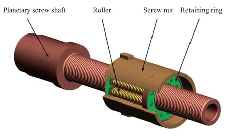
Figure 5 Schematic diagram of planetary roller screw pair

Figure 6 Schematic diagram of three redundant linear feedback potentiometers
2.3 Algorithm Simulation of the Electric Servo System
The electric servo system adopts a three-loop control strategy based on position,speed and current.The threeloop control model of the servo system is shown in Figure 7.The three-loop control model of the servo control algorithm consists of the position loop,the velocity loop and the current loop.Among them,the current loop utilizes a PWM wave generator,inverter,CLARK transformation,PARK transformation and PARK inverse transformation.PARK transformation and PARK inverse transformation include the position transformation of the rotating coordinate system,which requires the position feedback generated by the resolver.The velocity loop provides the quadrature position angle through resolver feedback,and then calculates the velocity through the position decoding chip.The position loop provides position feedback from the feedback potentiometer mounted on the load.The three closed loops were connected by a Proportional-Integral-Derivative (PID)regulator or other control algorithms to form a complete closed loop model.
3 CONTROL ALGORITHM DESIGN AND VERIFICATION
The control object of the booster servo system in the LM-6A launch vehicle was the flexible nozzle of the solid motor,where the load moment was quite large (55 kNm),and the load characteristic is nonlinear.However,the electric servo system based on a permanent magnet synchronous motor is a multi-variable,strong coupling,nonlinear time-varying parameter system,hence a reasonable control algorithm needed to be designed to achieve good control of the controlled object.
In order to meet the performance requirements under different working conditions,the electric servo system needed to meet the dynamic characteristics requirements under four test conditions,including two swing angle commands of 0.3° and 0.5°and two offset displacements of 0° and 2°.However,it was difficult to achieve this only by using a conventional three-loop PID control algorithm.Through the full-band frequency-scanning test results in Figure 8,it can be seen that in the high frequency band above 15 Hz,the amplitude cannot be rapidly attenuated below the index,which did not meet the requirements of system dynamic characteristics.
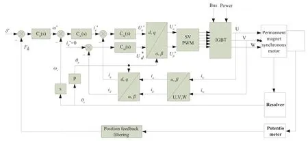
Figure 7 Block diagram of servo system control algorithm
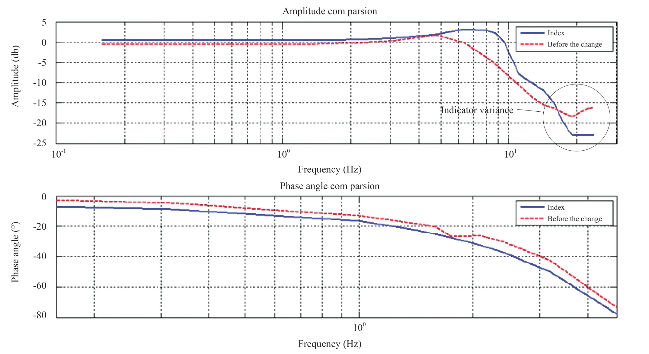
Figure 8 Frequency-scanning test results of electric servo system (conventional PID control algorithm)
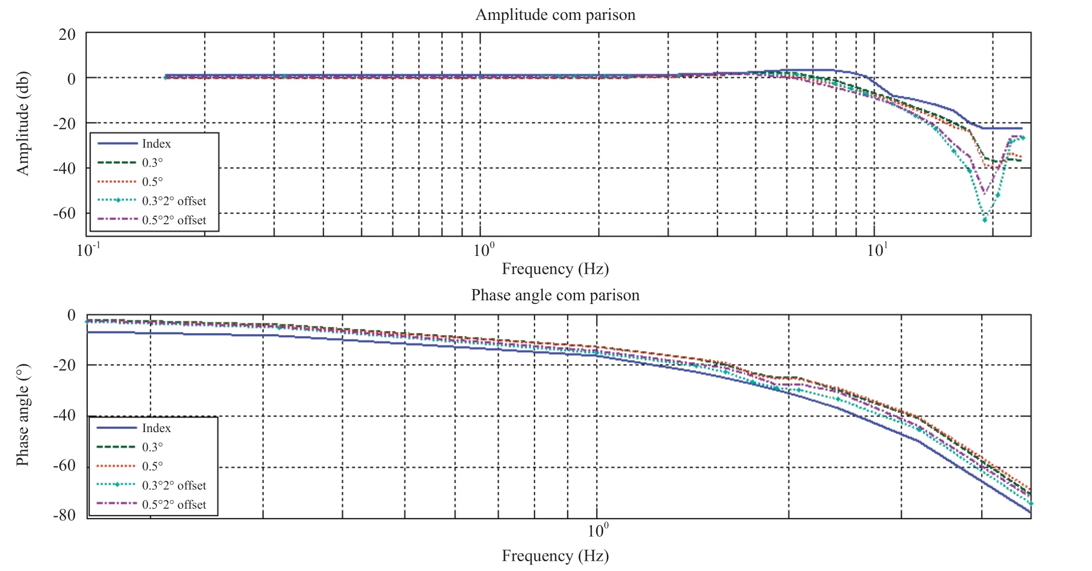
Figure 9 Frequency-scanning test results of electric servo system (three-loop PID +advanced correction+double notch filter)
In order to solve the problem of the high-frequency amplitude being out-of-tolerance,a second-order notch filter was designed in the high-frequency band.As a single notch filter cannot improve the amplitude over the whole frequency band,so adding just a single second-order notch filter at the high-frequency end,the amplitude of the medium-low frequency band will appear resonance and have poor performance.Therefore,two second-order notch filters were designed in the medium and high frequency bands to reduce the influence on the amplitude characteristics of the low frequency band.On this basis,an advanced correction network was added to further optimize the problem of low-frequency amplitude uplift.
The mathematical model of the second-order notch filter is as follows:
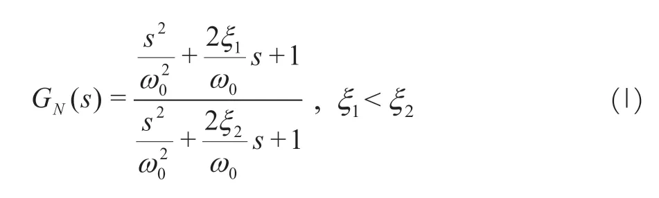
According to the load characteristics of the control object,the notch center frequency ,notch depth and notch width of the two second-order notch filters can be determined,so the model parameters of the notch filter can be accurately calculated according to the following formula.
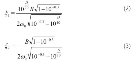
The mathematical model of the advance correction network is as follows:
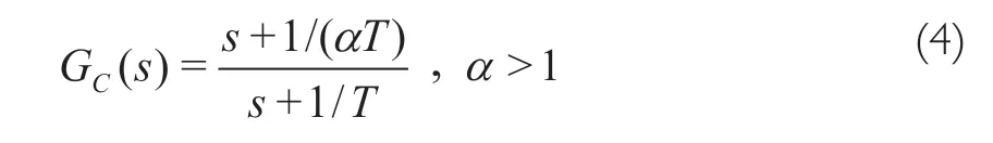
By designing advanced correction network and double notch filter,the load dynamic characteristic under various test conditions was realized.
4 CONCLUSION
The LM-6A launch vehicle adopts four high-power electric servo systems,which are respectively matched with four solid boosters.A single set of electric servo system includes one servo control driver and two electric servo mechanisms.The servo control driver realizes the functions of 1553B bus communication,servo control algorithm operation,signal acquisition and processing,servo motor drive control.In order to solve the problem of out-of-tolerance in system dynamic characteristics,the algorithm architecture of an advanced correction network and double notch filter was designed,and experimental verification was conducted to prove that the dynamic characteristics requirements under multiple operating conditions were met.The electric servo mechanism integrates the high-power servo motor,the high-thrust planetary roller screw pair,and three redundant feedback potentiometers to realize the two-way swing of the flexible nozzle of the solid motor.The research results provide references for the development of subsequent similar products or higher-power electric servo systems.
- Aerospace China的其它文章
- Research on Unattended Loading Technologies of the New Generation Launch Vehicles
- Adaptive Reconfiguration for Launch Vehicle Under Servo Mechanism Fault
- Research and Application of High-Voltage Power Supply and Distribution on Launch Vehicle
- Research on Key Technologies of Segmented Solid Rocket Booster
- Research on Modal Test Technology of LM-6A Solid-Liquid Strap-On Launch Vehicle
- Study on the Effect of Solid Particles on Jet Flow and Base Thermal Environment for Solid-Liquid Bundled Rocket