Numerical simulation of fueling pellet ablation and transport in the EAST H-mode discharge
Wan-Ting Chen(陈婉婷), Ji-Zhong Sun(孙继忠), Fang Gao(高放), Lei Peng(彭磊), and De-Zhen Wang(王德真)
Key Laboratory of Materials Modification by Laser,Ion,and Electron Beams(Ministry of Education),School of Physics,Dalian University of Technology,Dalian 116024,China
Keywords: deuterium pellet,fueling,EAST,SOLPS-ITER
1. Introduction
One of the most critical issues for steady-state operation of magnetic confinement plasma fusion devices is the large fuel loss from the central region of a tokamak plasma.Plasma fueling is important and necessary for long-duration discharges and improving the energy confinement. Cryogenic deuterium(D)pellet injection[1]is considered to be a promising technique for plasma core fueling due to its deep penetration and high fueling efficiency,and has been chosen as a primary fueling method for ITER.[2]Many investigations on pellet fueling have been performed on different tokamaks.[3,4]In DIII-D,the realization of both L–H transition and a 300 ms Hmode confinement time was facilitated by D pellet injection.[5]In addition,high-density H-mode operation at 1.5×the Greenwald density limit was realized by repeated D pellet injections on ASDEX.[6]Pellet injection from the high-field side(HFS)was reported to increase both the penetration and the fueling efficiency via ∇B-induced drift.[7–9]Pellet injection has also been used successfully for the control of edge localized modes(ELMs),[10]through which the peak flux of individual bursting of ELMs is reduced by increasing their frequency. Experiments conducted on ASDEX found that with D pellet injection large ELMs were completely replaced by smaller ELMs.[11]Pellet pacing experiments were then carried out on HL-2A and JET with many positive results.[12,13]
EAST is a fully superconducting tokamak equipped with advanced pellet injection systems[14]that can work with different injection positions, speeds and frequencies. Pellet fueling experiments on EAST found that the electron density suddenly increased after the injection of D pellets from the HFS at 250 m/s, and the central electron temperature decreased significantly.[15]However, a different result has also been observed, which showed that there was no significant change in the edge electron temperature after pellets were injected from the low-field side (LFS) at 100 m/s.[16]The confinement of plasma was improved and the stored energy was enhanced when the pellet particles were mostly deposited near the pedestal region.However,large pellets introduced a strong density perturbation and degraded the confinement, as also demonstrated experimentally.[17]During the fueling experiments,ELMs were also triggered with the injection of shallow pellets. A series of experiments[18]were then carried out to study the appropriate pellet parameters for ELM pacing,which can provide data references for ITER. Although many pellet injection experiments including plasma fueling and ELM pacing have been carried out, there is little quantitative knowledge about atomic evolution at the scrape-off layer(SOL)due to a shortage of effective diagnostic methods. In addition,there are also few convincing experimental results on temperature variation after pellet injection due to large uncertainties in the relevant diagnostics. To the best of our knowledge,the ELM triggering effects of D and Li pellets have not been compared experimentally or numerically. All of this calls for a detailed study by numerical simulation to provide theoretical assistance for experiments.
In this work, a modified dynamic neutral gas shield(DNGS) model[19]and edge plasma transport package SOLPS-ITER[20]were used to study the ablation of D pellets and the transport of D species in both atomic and ionic states with reference to the H-mode discharge experiment parameters in EAST.In previous works by Gaoet al.[21,22]the model was used to study the injection of Li pellets for ELM pacing,and a specific technique was developed to couple the data for the time-varying spatial distribution of neutral species evaluated from DNGS into SOLPS-ITER. The predicted trigger rates with different radii were in good agreement with those of the experiments. The present work focuses on the response of background plasma after D pellet injection and studies the influence of pellet parameters on fueling and ELM pacing. This paper is organized as follows. The physical model and simulation setup are described in Section 2. The results and discussion are presented in Section 3 and the conclusions are given in Section 4.
2. Simulation details
2.1. Ablation model
After pellets enter the background plasma they will undergo a series of physical processes including ablation,neutral atom ionization and plasma transport. The neutral gas shield(NGS) model,[23]which is in qualitative agreement with the experimental results, has been widely used for the evaluation of pellet ablation. It is considered that the ablation gas, a spherically symmetric neutral cloud formed around the solid pellet, shields most of the incident energy flow. As in the model,the atomic ablation rate is given as

whereneandTeare respectively the electron density and temperature of the background plasma,rpis the pellet radius andMiis the atomic mass. However,the motion of pellets through the plasma is neglected. In the core plasma, the temperature and density slowly vary radially; however, in the pedestal region the variation is very rapid. Therefore, the variations in temperature and density should be taken into account. For this purpose,a modified NGS model[19]is employed in the present work. In the model, the pellet is assumed to move across the plasma with a constant velocityvp. Therefore, its movement distanced(t)is approximated by

The pellet is injected from the outer boundary of the SOL att=0 at the outer mid-plane(OMP).The electron density and temperature of the background plasma experienced by the injected pellet(as shown in Fig.2)can be expressed as a function ofd(t)via the relationR-Rsep=Lsol-d(t),whereLsolis the width of the SOL.Then by using Eq.(1),the space–time varying density of the D atomic number can be evaluated by a method in Ref. [22], which is introduced in the following section.
2.2. Simulation setup
In this work, background plasma profiles from the Hmode real discharge data on EAST (shot No. 70601) are reconstructed with the SOLPS-ITER code package. D2,D,D+,D+2,and electrons are considered. Ions and electrons are simulated by the multi-fluid transport code B2.5 with a quadrilateral grid and the neutral particles are handled by the Monte Carlo neutral transport code EIRENE with a triangular grid.An upper-single null magnetic field equilibrium for EAST is used in this study,and the simulation mesh is shown in Fig.1.As the red arrow shows,the D pellet is injected from the OMP where an encrypted grid is used to obtain a higher spatial resolution of density.

Fig. 1. SOLPS simulation mesh with EAST upper-single null equilibrium.The locations of pellet injection and the pumps are marked in the sketch.Here, IT, OT, and MCW represent the inner target, outer target and main chamber wall,respectively.
According to the experimental data,the input power from the core boundary to the SOL is set toPsol=2.2 MW,which is equally split into ions and electrons,and the density of D+at the inner boundary, set atR-Rsep=-15 cm at the OMP,is fixed tonD+=6.2×1019cm-3. The default sheath boundary condition at the target is applied and the leakage boundary condition is adopted for the SOL/private flux region. To reflect the pumping effect,the recycling coefficients at the pump entrance as shown in Fig. 1 are set to 0.8, while those at the target plates and the first wall are set to 1.0. Drifts are not considered in this paper due to the numerical difficulty. To simulate the H-mode discharge, the background temperature and density profiles consistent with the experimental data were reconstructed using the radial particle and thermal diffusivity coefficients combined with boundary conditions. The plasma profiles and diffusivities at the OMP are shown in Fig.2.

Fig.2. Experimental and SOLPS reconstructed plasma profiles at the outer mid-plane and radial diffusivity coefficients used in the simulation: (a)electron density, (b) electron temperature, (c) radial particle and thermal diffusivity coefficients. Five sets of experimental data at five times during the H-mode discharge(shot No.70601)were used to obtain the fitting profiles to reduce the background fluctuations.
To consider the effects of pellet injection on the background plasma, the ablation atomic densityn(t) introduced into the continuity equation in SOLPS as the source term is calculated fromG(t)in Eq.(1)
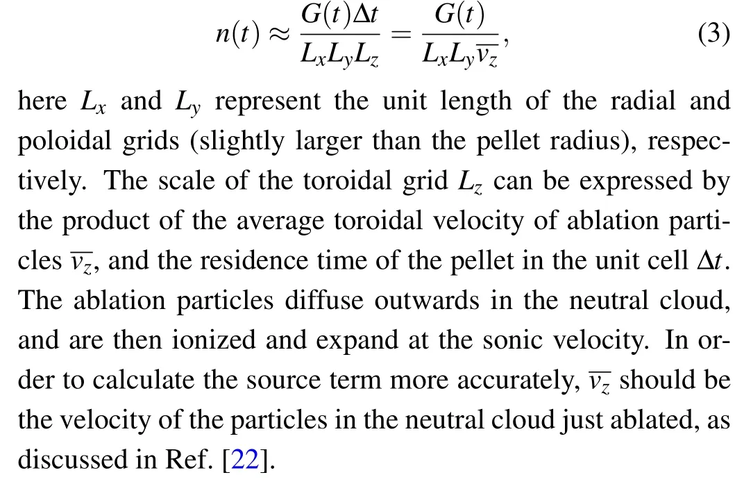
3. Results and discussion
In EAST experiments,[24]D2gas is frozen and cut into cylindrical solid pellets with diameter of 1.5 mm and length of 1.2/1.5/1.8 mm and then injected at a speed of 100 m/s–300 m/s. In the DNGS model, the pellet is assumed to be spherical,so a cylindrical pellet in experiments can be approximated by a spherical pellet with a radius of 0.8/0.86/0.91 mm based on particle number conservation. In the simulation,the parameters of the pellet are selected with reference to the experiments. The pellet is injected from the OMP; its radius is in the range of 0.8 mm–1.2 mm and its injection speed in the range of 100 m/s–300 m/s.
3.1. Effects of D pellet injection
As shown in Fig. 3, the ablation rate is at first relatively low in the SOL,but after entering into the separatrix ablation is then intensified remarkably due to the rapid enhancements in both background plasma density and temperature. As the pellet radius reduces gradually with ablation,the ablation rate begins to decrease after reaching a peak.
The evolution of the electron density and electron and ion temperatures in the OMP is shown in Fig.4. From Fig.4 we can see that the electron density increases noticeably 0.5 ms after the pellet is injected, and the electron density perturbation moves inward as the pellet moves,indicating that the ionization of ablated atoms densifies the plasma locally.The electron temperature falls first due to inelastic collisions but then recovers quickly,which is not noticeable in Fig.4(b). In contrast,the ion temperature decreases evidently and takes about 1 ms to reach its initial state,as can be seen clearly in Fig.4(c).Compared with the ion temperature, the electron temperature quickly recovers from the perturbation.
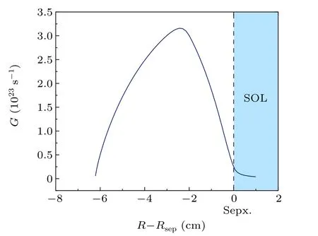
Fig. 3. The ablation rate of a D pellet at the outer mid-plane. The pellet moves inward from the SOL(i.e.,the colored region where R-Rsep is positive)with a radius of 0.8 mm and injection velocity of 100 m/s.
The distribution of the atomic density of D at different ablation times(0.1,0.2,0.3,0.4,0.5,and 0.6 ms after injection)is presented in Fig.5. In the first three snapshots of Fig.5 we can see there are considerable numbers of neutrals in the SOL.After the pellet moves further inside the seperatrix,the distribution of the neutrals looks distinctively different: there is an atomic layer around the pellet. The distribution of the neutrals in the radial direction is presented in Fig.6(a). It can be seen that the atomic density in the SOL does not rise significantly at 0.1 ms (at the time the pellet is still in the SOL), while it increases rapidly at 0.2 ms and 0.3 ms (the pellet is already 1 cm–2 cm inside the separatrix).

Fig.4.Evolution of(a)electron density,(b)electron temperature and(c)ion temperature in the outer mid-plane,with density in units of m-3 and temperatures in eV.The pellet is injected at 0.5 ms with a radius of 0.8 mm and injection velocity of 100 m/s.
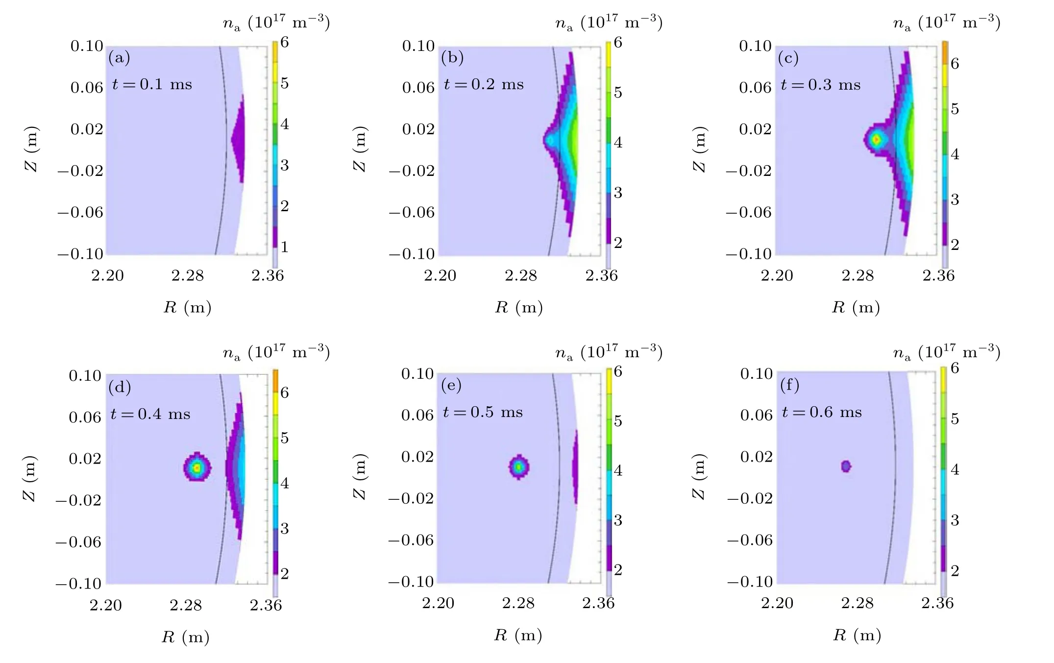
Fig.5. Distribution of the atomic density of D at different ablation times. The black lines represent the location of the separatrix(rp=0.8 mm,vp=100 m/s).
From these results we know that strong ablation takes place inside the separatrix, and that many ablated atoms return to the SOL when they are near the separatrix,as shown in Fig.6(b). Since both the electron density and temperature are low,weak ionization has much less effect on the neutral density in the SOL.There is another reason for this:the movement of neutrals is determined by collisions and is not confined by the magnetic field.They move much more slowly than charged particles. Thus, a high atomic density occurs in the SOL.As the pellet goes deeper, the outflow of neutral particles weakens and the atomic density in the SOL falls. When the pellet is deeper inside the separatrix,the nearby ablated neutrals are more likely to be ionized in a shorter time period and then confined inside the separatrix by the magnetic field. In fact,atomic deposition in the SOL is closely related to the injection velocity and will be discussed in detail in the next section.
The profiles of electron density at different times after injection of a pellet from the OMP are shown in Fig.7(a). As can be seen, the electron density becomes higher with time before it peaks at the top of the pedestal, at a maximum of 7.5×10¹⁹m-3.The electron density then drops as the ablation rate decreases,with the deepest distance within the separatrix being approximately 6 cm. In Fig.7(b),a local drop in the ion temperature occurs since the ionization of the ablated neutrals consumes energy. However, the ion temperature in the SOL rises as some ions with higher energy diffuse into the SOL from the region near the separatrix.
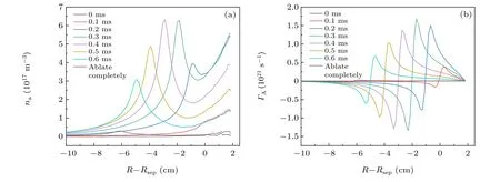
Fig. 6. Profiles of (a) atomic density and (b) radial atomic flux (the outflow is positive) at the outer mid-plane at different times during pellet injection(rp=0.8 mm,vp=100 m/s).

Fig.7. Profiles of(a)electron density and(b)ion temperature at the outer mid-plane at different times during pellet injection(rp=0.8 mm,vp=100 m/s).
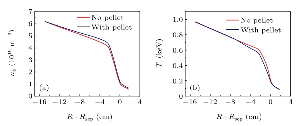
Fig.8. Electron density and ion temperature profiles at the outer mid-plane without pellet injection. It takes about 1 ms to recover from the perturbation after pellet injection(rp=0.8 mm,vp=100 m/s).
After the background plasma has recovered from the perturbation, the electron density rises and the fuel particles are almost all deposited within the separatrix at 2 cm–6 cm, as shown in Fig.8.Due to inward particle transport,the core density also increases slightly, while the ion temperature is only reduced in the main ionization region.
3.2. Pellet size and injection velocity
The pellet size and injection velocity are two main parameters that affect the fueling performance. We can adjust the pellet size and injection velocity to control the amount and location of deposition. Figure 9 compares the ablation atomic density with different pellet radii and injection velocities.With the same injection velocity,a larger pellet size leads to deeper penetration and a higher ablation atomic density, while with the same pellet size an increase in injection velocity leads to a decrease in ablation atomic density.
The experiments on DIII-D[25]show that a pellet injected with high velocity can increase the penetration and fueling efficiency (defined as an increased number of plasma electrons divided by the number of fuel atoms). The atomic deposition in the SOL found in Subsection 3.1 is very sensitive to the pellet velocity. Figure 10(a) shows the evolution of atomic density in the SOL (R-Rsep=1 cm). With the increase in pellet velocity, the atomic density in the SOL decreases evidently due to the reduction of out-diffusion of D atoms from the separatrix,and the deposition time is also shortened. Figure 10(b)shows the evolution of radial atomic flux at the separatrix during pellet injection. In this figure,the negative flux means that the net particle flux goes into the separatrix; the negative flux occurring in the initial stage is mainly due to the particle influx resulting from the pellet moving in the SOL but near the separatrix, and the time of the influx is short. As time advances,the radial atomic flux builds up quickly as the pellet moves across the seperatrix. When the pellet velocity is higher, the deposited atomic profile broadens, and its peak drops and stays further away from the separatrix. As a result,the atomic outflux into the SOL becomes weaker. The higher injection velocity reduces the ablation in the pedestal region and effectively decreases the outflow of particles, so a higher injection velocity is preferred to reduce the expulsion of fueling particles from the discharge and improve the fueling efficiency. However, the loss of neutrals due to this mechanism accounts for only a small percentage. A much large percentage of fueling loss observed in experiments must have been caused by other channels.[26]
Figure 11 shows the evolution of electron density after the injection of pellets with different radii. As pellet size increases, the peak electron density grows significantly. It can be seen that the amplitude of the perturbation density peak can reach six times that of the initial density with a pellet of radius 1.2 mm, while the peak density is no more than twice the initial density with a pellet of radius 0.8 mm. The higher injection velocity makes the pellet deposit fewer neutrals per unit length,i.e. the perturbation density is lower,and the pellet moves further into the plasma core, as shown in Fig. 12.The strong density perturbation will cause instability and affect the steady-state operation of the plasma. The profiles in this work can be used as input for advanced MHD models such as BOUT++to analyze the plasma response in detail.[27]
In previous work[22]on ELM triggering by Li pellets we found that the triggering rate depends strongly on the pellet size;the aim was to provide a density perturbation in the gradient region of the background plasma. The use of pellets for fueling requires efficient fueling deep inside the separatrix without causing unacceptable perturbation. Thereby,effective optimization of fueling is benefited by a higher injection velocity.
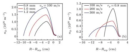
Fig. 9. Ablation atomic densities of D pellets at the outer mid-plane with different(a)pellet radii and(b)injection velocities.
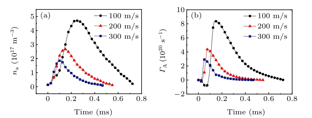
Fig. 10. Evolution of (a) atomic density in the SOL and (b) radial atomic flux at the separatrix (the outflow is positive) during pellet injection (rp =0.8 mm).

Fig.11. Profiles of electron densities at the outer mid-plane for different pellet radii: (a)0.8 mm,(b)1.0 mm,(c)1.2 mm.

Fig.12. Profiles of electron densities at the outer mid-plane for different injection velocities: (a)100 m/s,(b)200 m/s,(c)300 m/s.
3.3. Ablation rates of D and Li pellets for ELM triggering

Fig. 13. Ablation rates of D (red line) and Li (blue line) pellets injected from the outer mid-plane with the same size (rp = 0.8 mm) and velocity(vp=100 m/s).
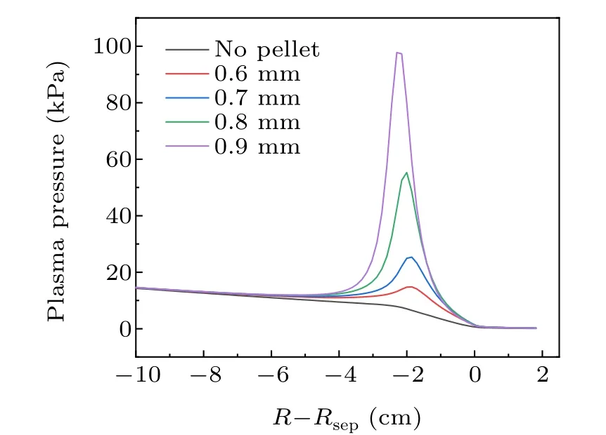
Fig. 14. Plasma pressures at the moment of maximum ablation caused by different-sized pellets(vp=100 m/s).
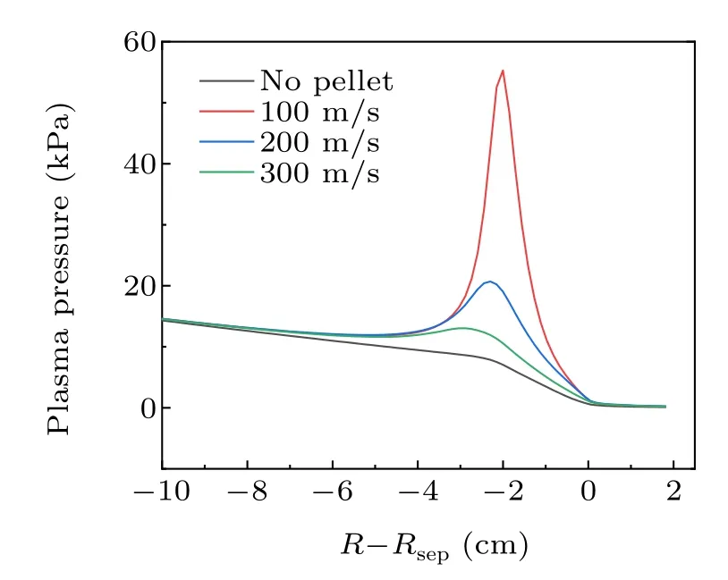
Fig. 15. Plasma pressures at the moment of maximum ablation caused by different injection velocities(rp=0.8 mm).
It has been demonstrated experimentally that both D and Li pellets injected into the pedestal can trigger ELMs. However,the difference between fuel and impurity pellets for ELM triggering remains unclear. The ablation rates of D and Li pellets in the pedestal are plotted in Fig. 13 for the same injection conditions. As can be seen, the D pellets ablate more intensively with a higher ablation rate, which can be understood easily from the big difference in the sublimation energy(0.005 eV per D atom compared with 1.6 eV per Li atom). In the pedestal the ablated particles are ionized and radially confined there.Figure 14 presents the plasma pressures at the moment of maximum ablation caused by different sized D pellets.Compared with the previous study of Li pellets[22]the maximum perturbed pressure resulting from D pellets of the same size is obviously higher, although a D atom only contributes one electron whereas one Li atom contributes three electrons after it has been completely ionized. In Subsection 3.2 we found that increasing the injection velocity would reduce the strength of the density perturbation. When the injection velocity is reduced from 300 m/s to 100 m/s,the maximum perturbation pressure is enhanced and the peak pressure moves back a little closer to the SOL,as shown in Fig.15. For ELM pacing, the injection velocity should not be too large in case the pellet does not deposit its neutrals in the pedestal region.Moreover,the ELM triggering effciiency is also related to the deposition position of pellet particles. Pellet particles depositing in the steep pedestal region are more favorable for ELM triggering than those depositing on the pedestal top.[28]We can adjust the injection velocity to control the location of deposition in the pedestal region.
4. Conclusion
The dynamic neutral gas shield model combined with the edge plasma code SOLPS-ITER has been employed to study the ablation and transport of D pellets with reference to EAST experiments. The present work found that the background plasma was locally much affected by an injected pellet with the parameters used in EAST experiments: the electron density was raised while the electron and ion temperatures dropped locally, but the disturbance to the electron temperature was not so noticeable as that to the ion temperature. Deuterium atoms distributed circularly around the moving pellet, and some of them deposited evidently in the SOL due to the transiently enhanced particle out-diffusion after the pellet moves across the separatrix. Increasing the pellet velocity could effectively reduce atomic deposition in the SOL and thus improve the fueling efficiency. Compared with Li pellets, D pellets ablated faster and more intensively, and the pressure perturbation to the background plasma was significantly higher than for Li pellets of the same size. The maximum perturbed pressure was sensitive to the injection velocity but the position of the maximum perturbed pressure depended only weakly on injection velocity. This conclusion was important for ELM triggering experiments. In future work, the influence of classical drifts on the ionized particles in the HFS/LFS will be analyzed. Meanwhile, due to the difficulty of injecting pellets from the inner mid-plane in practice,as an alternative integrating Zhang’s areal deposition model[29]with the SOLPS code will be undertaken to carry out injection from the HFS with an arbitrary angle.
Acknowledgments
Project supported by the National Key R&D Program of China under Grant Nos. 2017YFE0301100 and 2019YFE03030004, the National Natural Science Foundation of China under Grant No. 11575039, and Users with Excellence Program of Hefei Science Center CAS(2020HSCUE010).
- Chinese Physics B的其它文章
- Real non-Hermitian energy spectra without any symmetry
- Propagation and modulational instability of Rossby waves in stratified fluids
- Effect of observation time on source identification of diffusion in complex networks
- Topological phase transition in cavity optomechanical system with periodical modulation
- Practical security analysis of continuous-variable quantum key distribution with an unbalanced heterodyne detector
- Photon blockade in a cavity–atom optomechanical system

