Rotordynamic characteristics prediction for scallop damper seals using computational fluid dynamics
Wnfu ZHANG, Lu YIN, Li YANG, Hoyng TIAN, Chun LI
a School of Energy and Power Engineering, University of Shanghai for Science and Technology, Shanghai 200093, China
b Electric Power Research Institute of State Grid, Shanghai Municipal Electric Power Company, Shanghai 200437, China
KEYWORDS Computational Fluid Dynamics (CFD);Effective damping;Rotordynamic characteristics;Scallop damper seal;Stability
Abstract Enhancing damping characteristic is one of the effective methods to solve the instability problem of the rotor system. The three-dimensional numerical analysis model of scallop damper seal was established, and the effects of inlet pressures, preswirl ratios, rotational speeds, interlaced angles and seal cavity depths on the rotordynamic characteristics of scallop damper seal were studied based on dynamic mesh method and multi-frequencies elliptic whirling model.Results show that the direct stiffness of the scallop damper seal increases with decreasing inlet pressure and increasing rotational speed and cavity depth.When the seal cavity is interlaced by a certain angle,which shows positive direct stiffness.The effective damping of the scallop damper seal increases with the increasing inlet pressure, the decreasing preswirl ratio and the rotational speed and cavity depth. There exists an optimal interlaced angle to maximize the effective damping and the system stability.The leakage of the scallop damper seal is significantly reduced with decreasing inlet pressure.The preswirl will reduce the leakage flowrate,and the rotational speed has a slight effect on the leakage performance.The leakage of the scallop damper seal decreases with increasing seal cavity depth.©2021 Chinese Society of Aeronautics and Astronautics.Production and hosting by Elsevier Ltd.This is an open access article under the CC BY-NC-ND license(http://creativecommons.org/licenses/by-nc-nd/4.0/).
1. Introduction
The annular seal is an important component of turbomachinery, which affects the safe and efficient operation of the unit.Reducing fluid leakage and enhancing system stability are two important goals to evaluate the sealing performance.With the continuous improvement of unit parameters, the system instability induced by the unsteady flow inside the seal cavity becomes increasingly prominent.Improving the seal dynamic stability is one of the focuses and challenges in current research.
The conventional labyrinth seals play an important role in reducing the leakage flow rate of fluid in turbomachinery,such as aeroengines, gas turbines and steam turbines, and improving unit efficiency. However, their poor rotordynamic performance may easily lead to the instability problem of the rotor system, which severely limits their application in turbo machines.At present, the main methods for improvement of the system stability consist of swirl brakes, anti-swirl flow and damper seal technology. The anti-swirl flow technology mainly injects the fluid opposite to the rotation direction of the rotor into the seal cavity to attenuate the tangential velocity of the fluid, but improper anti-swirl flow can easily cause the instability.
The damper seal technology is one of the effective methods to alleviate the instability fault of the rotor system brought by the conventional seal structure. In 1982, Von Pragenaufirst proposed the concept of damper seal, which indicated that the roughness of the stator surface could be increased by changing the structure of the stator surface, so that the dynamic characteristics of the seal could be improved, then the system stability was enhanced. In recent years, researchers have successively proposed and studied various damper seal structures such as honeycomband hole-pattern.These structures have shown good performance in field applications.In 1993,Vance et al.proposed a new structure of the labyrinth seal (TAMSEAL), the so called Pocket Damper Seal(PDS). Experimental measurements indicated that this seal provides a considerable direct damping (about 100 times that of conventional labyrinth seals), which can effectively reduce the rotor vibration amplitude. Its radial and tangential seal force opposite to the rotor whirling speed,and the rotor whirling amplitude is effectively reduced. What is more, compared with the honeycomb seal and hole-pattern seal, the PDS also has advantages such as low manufacturing cost, corrosion resistance, simple structure and long service life. However,the negative static direct stiffness is limited to the specific operating conditions:choked exit flow condition and low eccentricity ratio less than the crossover eccentricity ratio, where the pocket damper seal would be statically unstable.In addition,the circumferential baffle usually needs special welding, relatively difficult to manufacture.
To further enhance the damping characteristics, and improve the system stability and manufacturing efficiency,Takahashi et al.first proposed a scallop-shaped seal structure. Several scallop grooves are milled on the smooth stator surface. Through the high-pressure compressor with electromagnetic exciter, the rotor stability of the new seal structure is tested.Results show that the damping coefficient can be significantly improved, and the theoretical prediction is in good agreement with the experiment. According to the concept of scallop damper seal,Griebelstudied the influence of seal cavity notch and baffle layout on the leakage and dynamic characteristics of the pocket damper seal, and pointed out that the chamfered baffle (scallop baffle) is an effective way to reduce the manufacturing cost of the pocket damper seal.Zahorulko and Leeused the unsteady CFD method for simulating shaft whirl motion (single-frequency trajectories method) and dynamic coefficients identification (instationary perturbation method) for damper seals. Results confirmed the fairly high dynamic characteristics of the scallop seal and their frequency dependencies. However, there are still few reports on the dynamic characteristics of scallop damper seals,particularly various geometries and working conditions under three-dimensional whirling motions.
This paper establishes a full three-dimensional numerical calculation model of the scallop damper seal. The Computational Fluid Dynamics (CFD) method is employed. The dynamic characteristics of the scallop damper seal are investigated based on the multi-frequencies elliptical whirling and dynamic mesh technology. Then the paper focuses on figuring out the effects of various inlet pressures, preswirl ratios, rotational speeds,interlaced angles and depths of the scallop cavity on the dynamic characteristics of the scallop damper seal.
2. Numerical method
2.1. Geometrical model
Fig.1 shows the two-dimensional geometric model of the scallop damper seal. The primary geometric parameters are listed in Table 1.The total length l of the seal section is 35.7 mm,and the rotor diameter d is 60 mm. The scallop damper seal consists of 10 straight teeth and 9 scallop cavities (C1-C9) along the flow direction. As shown in Fig. 1(b), eight scallopshaped cavities are evenly distributed in the circumferential direction on each seal cavity. The circumferential angle θ between two adjacent scallop-shaped cavities is 45°. To improve the manufacturing efficiency, the scallop cavity can be processed directly by a milling cutter tool with a diameter of 26 mm,which can effectively reduce the manufacturing cost of the traditional damper seal.
Fig. 2 shows the distribution of odd (C1, C3, C5, C7, C9)and even (C2, C4, C6, C8) seal cavities. The interlaced angle α refers to the interlaced rotation angle of two adjacent seal cavities in the circumferential direction. In this paper, the C1, C3, C5, C7, and C9 cavities are fixed, and the C2, C4,C6, and C8 cavities are rotated by the angle α along the rotational direction.
2.2. Numerical model
Fig. 3 shows the mesh distribution of the scallop damper seal with different interlaced angles. To enhance the calculation accuracy, the structured mesh grid is employed, and the mesh in the seal clearance is locally refined.After verification of grid independence, the mesh density is finally determined to be about 1.83 million,and Yvalues are all controlled within the range of 34-300.

Fig.1 Two-dimensional geometry model of scallop damper seal.
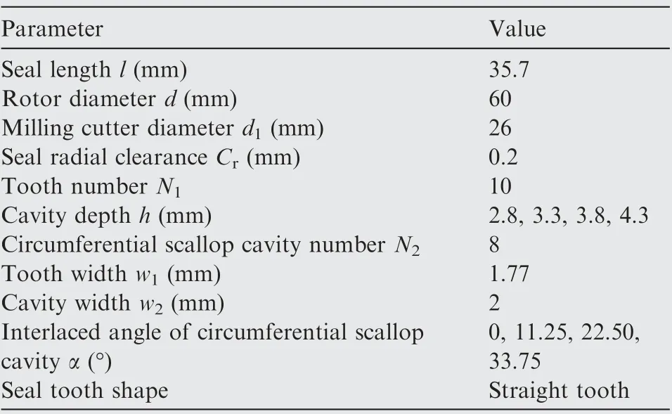
Table 1 Seal dimensions.
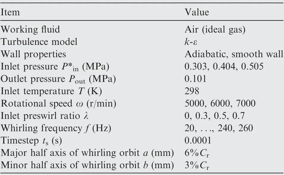
Table 2 Calculation conditions.
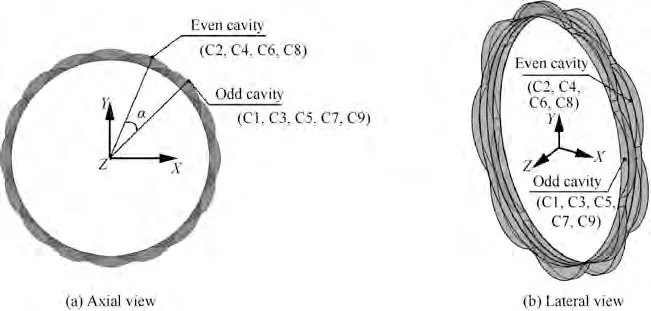
Fig. 2 Schematic diagram of cavity distribution for interlaced scallop damper seal.
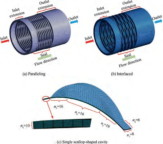
Fig. 3 Mesh distribution of scallop damper seal.
Table 2 gives the calculation boundary condition. The turbulence model uses the k-ε turbulence model with a turbulence intensity of 5%. The total pressure is set at the seal inlet to be 0.505 MPa and the inlet temperature to be 298 K.The average static pressure at the outlet is 0.101 MPa, and the rotational speed is given at 5000 r/min. The solid wall surface is set as an adiabatic, smooth and non-slip wall surface. The dynamic mesh method is used to simulate the elliptical whirling orbit of the rotor. The steady state solution is first carried out.The residual value is reduced to 10, and the difference of the leakage flow rate value is less than 0.1%, which is considered that the computational convergence is satisfied. Then, as the curves of Fand Fof flow-induced forces acting on the rotor are smooth and periodic,meanwhile,the forces at corresponding points in different periods differ less than 0.5%, the transient calculation is considered to be convergent.
2.3. Rotordynamic coefficients solution
Assuming the rotor makes a small whirling orbit around the seal center, the flow-induced forces Fand F, dynamic force coefficients, whirling displacement and velocity can be described linearly as follows.

where a and b are the lengths of major and minor semi-axis of the elliptical orbit respectively; Ωis the whirling speed of rotor; N is the number of whirling frequencies.
Fast Fourier Transform (FFT) of Eq. (1) can be expressed as
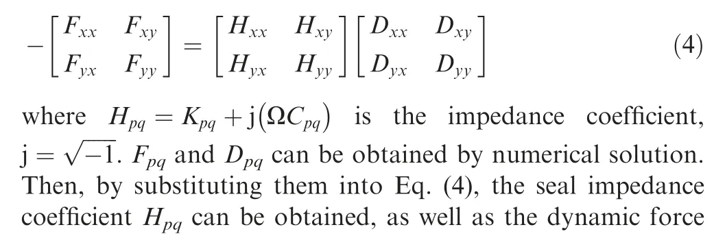
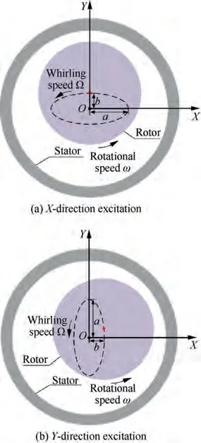
Fig. 4 Whirling orbit for rotor whirling at a single frequency.
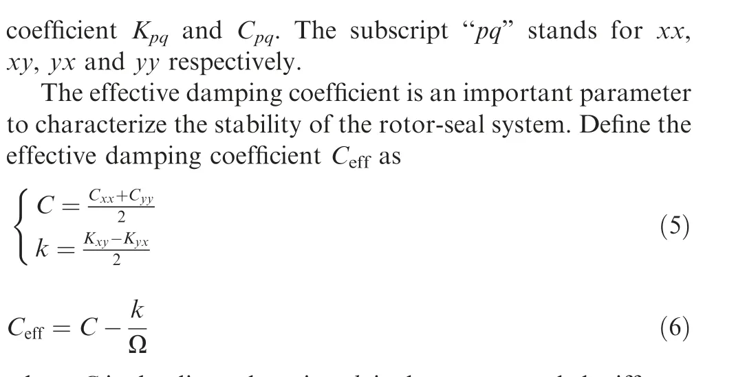
where C is the direct damping,k is the cross-coupled stiffness,and Ω is the whirling speed. Direct damping C and crosscoupled stiffness k are the two main parameters that determine the effective damping C. A larger the effective damping Cis beneficial to the stability of the rotor-seal system.
2.4. Case verification
To verify the numerical calculation method, the experimental labyrinth seal and pocket damper seal model from Ertas et al.are modeled. The numerical calculation results are compared with the experimental results.
Fig. 5 displays the comparison between numerical calculation and experimental results. The results show that the numerical simulation in this paper show a pretty good prediction in the direct and cross-coupled stiffness, damping, as well as the effective damping of the labyrinth seal and the pocket damper seal. It verifies the reliability of the numerical method in identifying the dynamic force coefficient of the seal.
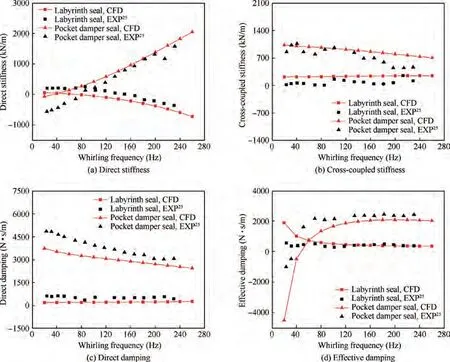
Fig. 5 Comparison of experiments and current CFD results.
3. Results and discussion
3.1. Analysis of flow field inside seal cavity
Figs.6 and 7 show the velocity and pressure distribution in the first seal cavity for X direction excitation, t = 0.1 s. The scallop damper seal is evenly divided into eight independent scallop cavities along the circumferential direction. The baffle structure between the two independent scallop cavities partially obstructs the circumferential flow inside the seal cavity.Complex vortex flows could be found in each individual scallop-shaped chamber. The viscous dissipation of the fluid in the seal cavity is strong, and a low velocity region appears at about - 3°, +2° and ± 6° away from the Y axis, respectively, which effectively reduces the fluid velocity. Among them, a positive sign indicates an offset along the right side of the Y axis, and a negative sign indicates an offset along the left side of the Y axis. The baffle and the scallop-shaped structure of the seal inhibit the fluid flow in the circumferential direction,while the fluid can be compressed and expanded to a certain extent in the closed,independent scallop-shaped chamber. Thereby the seal produces a higher damping, which helps to improve the system stability. The pressure in the seal cavity shows nonuniform distribution in the circumferential direction. Because the rotor continues to whirling along the elliptical orbit, for t = 0.1 s, the rotor just whirls to the positive direction of the X axis.At this time,a small clearance appears in the positive X axis.
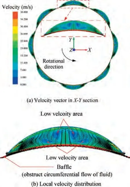
Fig. 6 Velocity distribution in seal cavity C1 (X-direction excitation, t = 0.1 s).
3.2. Rotordynamic performance for scallop seal
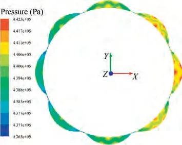
Fig. 7 Pressure distribution in seal cavity C1 (X-direction excitation, t = 0.1 s).
Fig. 8 shows the variation of dynamic characteristics of the scallop damper seal versus whirling frequency for different inlet pressures (P*= 0.303, 0.404, 0.505 MPa). The effect of inlet pressure on the direct stiffness is shown in Fig. 8(a).The direct stiffness increases with the decreasing inlet pressure,and the static stability of the seal system is better under low inlet pressure. For P*= 0.404, 0.505 MPa, the direct stiffness increases slightly with the increasing whirling frequency.For P*= 0.303 MPa, the direct stiffness is around 36 kN/m with the increasing whirling frequency, showing low frequency dependence and good static stability.
The cross-coupled stiffness, direct damping and effective damping of the scallop damper seal all increase with the growing inlet pressure.The increase in cross-coupled stiffness is not conducive to the stability of the rotor system, while the increase of direct damping is favorable, which is beneficial to improving the system damping and suppress rotor whirling.It can be seen from Fig. 8(d) that the effective damping increases with the increasing inlet pressure,so the scallop damper seal shows good dynamic stability.For P*=0.505 MPa,the effective damping increases by ~83% at the highest level comparing with that under P*= 0.303 MPa.
As shown in Fig. 9, the seal force acting on the rotor surface varies with time under different inlet pressures. It can be seen that the amplitude of the seal force increases significantly with the inlet pressure increases. Its damping characteristics are greatly improved, then the system stability could be enhanced.
The inlet preswirl is one of the important factors affecting the dynamic stability of the rotor. Inlet preswirl ratio can be defined as:

Fig. 8 Dynamic force coefficients vs whirling frequency at different inlet pressures (λ = 0, ω = 5000 r/min, α = 0°, h = 3.3 mm).

where c represents the rotor surface velocity, vdenotes the average circumferential velocity at the seal inlet.
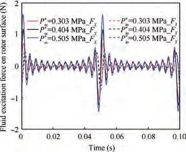
Fig.9 Fluid response force acting on rotor surface changes with time under different inlet pressures (X direction excitation).
Fig. 10 displays the variation of dynamic characteristics of the scallop damper seal versus whirling frequency for different preswirl ratios (λ = 0, 0.3, 0.5, 0.7). The effect of preswirl ratios on the direct stiffness is shown in Fig. 10(a). The negative direct stiffness is not conducive to the static stability of the seal system.At low preswirl ratio(λ ≤0.3),the direct stiffness increases with the increasing preswirl ratio and whirling frequency.Under high preswirl ratios(λ ≥0.5),growing the preswirl ratio increases the direct stiffness, which increases with the increasing whirling frequency for f ≤120 Hz.
Figs. 10(b) and (c) respectively show the variation of the cross-coupled stiffness and direct damping versus whirling frequency under different preswirl ratios. By increasing the preswirl ratio, all the positive cross-coupled stiffness of the scallop damper seal increases significantly, which may easily promote the rotor whirling.For λ=0,the cross-coupled stiffness shows significant frequency independence. For λ ≤0.3,the direct damping decreases with increasing whirling frequency and increases with the increasing of preswirl ratio(f ≠20 Hz). For λ ≥0.5, the direct damping increases with decreasing preswirl ratio at the low frequency region(f <100 Hz), and increases with increasing preswirl ratio at the high frequency region (f >100 Hz).
As can be seen from Fig.10(d),the effective damping of the scallop damper seal increases with the decreasing preswirl ratio, and the ability of suppressing the rotor whirling is enhanced,which is beneficial to the system stability.The effective damping is positive without preswirl,and shows a low frequency dependence. With the decreasing preswirl ratio, the crossover frequency decreases gradually, and the ability to improve the system stability is enhanced.
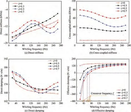
Fig. 10 Dynamic coefficients vs whirling frequency at different preswirl ratios (P*in = 0.505 MPa, ω = 5000 r/min, α = 0°,h = 3.3 mm).
Fig. 11 shows the circumferential velocity distribution along the leakage direction at the middle position of the seal clearance under different preswirl ratios. For λ = 0, the circumferential velocity shows a negative sign.For λ >0,the circumferential velocity is positive, and decreases along the leakage path. With the continuing increase of the preswirl ratio, the circumferential velocity increases and deteriorates the system stability.
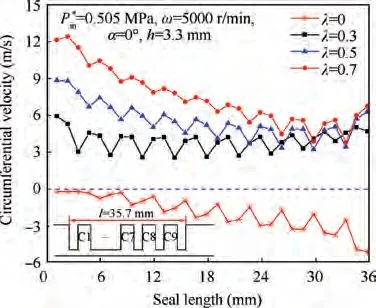
Fig. 11 Circumferential velocity distribution along leakage direction under different preswirl ratios.
Fig. 12 displays the variation of dynamic characteristics of the scallop damper seal versus whirling frequency for different rotational speeds (ω = 5000, 6000, 7000 r/min). The scallop damper seal at different rotational speeds shows negative direct stiffness.With the increasing rotational speed and whirling frequency,the direct stiffness increases,and the frequency dependence is strong. The cross-coupled stiffness is positive and increases with the increasing rotational speed. While the whirling frequency shows little influence on the cross-coupled stiffness. The direct damping increases with the increasing rotational speed and the decreasing whirling frequency. The effective damping is positive and increases with the decreasing rotational speed and the increasing whirling frequency, which is beneficial to suppressing rotor whirling and improving system stability.
Fig. 13 shows the distribution of the circumferential velocity in the seal cavity along the direction of the radial height at different rotational speeds. The circumferential velocity at each rotational speed close to the rotor surface is relatively large due to the non-slip boundary, and increases with the increasing rotational speed.The increase in the circumferential velocity of the airflow near the wall of the rotor caused by the increase of the rotation speed will cause the airflow in the two adjacent scallop-shaped cavities to produce circumferential flow, which will increase the imbalance of the circumferential pressure distribution in the seal cavity. At the same time, the velocity gradient near the wall of the rotor increases,which will cause the circumferential viscous sheer force of the fluid to increase. Therefore, the smaller the speed, the smaller the cross-coupled stiffness and the greater the effective damping,which is more conducive to the stability of the system.
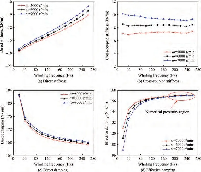
Fig. 12 Dynamic coefficients vs whirling frequency at different rotational speeds (P*in = 0.505 MPa, λ = 0, α = 0°, h = 3.3 mm).

Fig. 13 Circumferential velocity distribution along radial direction at different rotational speeds.
Fig. 14 shows the variation of dynamic characteristics of the scallop damper seal versus whirling frequency for different interlaced angles (α = 0°, 11.25°, 22.50°, 33.75°). Figs. 14(a)and (b) show the direct and cross-coupled stiffness. For α = 0°, it shows negative direct stiffness, otherwise it shows positive direct stiffness. There exists an optimum interlaced angle (~22.50°) to improve the static stability of the system.With the increasing whirling frequency, the direct stiffness increases.The cross-coupled stiffness is positive,and shows little frequency dependence. For α = 33.75°, the cross-coupled stiffness is relatively low.
Figs. 14(c) and (d) depict the direct and effective damping versus whirling frequency for different interlaced angles. The direct damping is relatively high for α = 11.25°. While it is very low as all adjacent seal cavities are parallelly juxtaposed(α = 0°). The effective damping increases with the increasing whirling frequency. The effective damping is relatively large for α=33.75°.For f ≥40 Hz,the effective damping is significantly smaller for α = 0°, and there is an optimal interlaced angle to make the system have the best stability (the optimal interlaced angle α calculated in this paper is 33.75°).The effective damping for α = 33.75° is about 111%-121% of that for α = 0°.
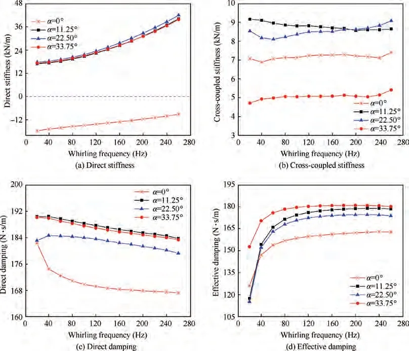
Fig. 14 Dynamic coefficients vs whirling frequency at different interlaced angles (P*in = 0.505 MPa, ω = 5000 r/min, λ = 0,h = 3.3 mm).
Fig. 15 shows the distribution of dynamic pressure monitoring points for scallop damper seals. The pressure inside the seal cavities C1, C2, C3 at α = 0°, 33.75° were monitored respectively. Eight monitoring points (P-P) were set along the circumference of each cavity. The dynamic pressure in the cavity that changes with time was shown in Fig. 15. The dynamic pressure of each monitoring point in the seal cavity varies periodically and the pressure distribution in the seal cavity is not uniform along the circumferential direction. Compared with the working condition of α=0°,the dynamic pressure under the working condition of α = 33.75° is relatively higher.It also can be seen that the high point of dynamic pressure in the cavity gradually decreases along the flow direction.For α = 0°, the highest pressure in the seal cavity (C1-C3)locates at P, while the lowest pressure locates at P. For α = 33.75°, the highest pressure of the seal cavity C1-C3 is located at P, the lowest pressure of the seal cavity C1 and C3 is located at P, and the lowest pressure of the seal cavity C2 is located at P.
From the above discussion, it can be seen that the scallop damper seal with α=33.75°possesses the best effective damping and stability.Therefore,to study the effect of the seal cavity depth on the dynamic characteristics of the scallop damper seal,the interlaced angle of the following computational model is designed to be 33.75°. The various seal cavity depths(h = 2.8, 3.3, 3.8, 4.3 mm) are analyzed.
Figs.16(a)and(b)display the variation of direct and crosscoupled stiffness versus whirling frequency for different seal cavity depths. The direct stiffness is positive with a large frequency dependence. The direct stiffness increases with the increasing whirling frequency and seal cavity depth. The cross-coupled stiffness is positive, and its overall trend increases with the increasing seal cavity depth.
Figs. 16(c) and (d) depict the variation of direct and effective damping versus whirling frequency for different seal cavity depths.The direct damping decreases slightly with the increasing seal cavity depth.A shallower depth seems to be beneficial to the damping enlargement. The effective damping increases with the decreasing cavity depth and increasing whirling frequency.The effective damping of the scallop damper seal with cavity depth of 2.8 mm is about 146%-211% that of 4.3 mm.
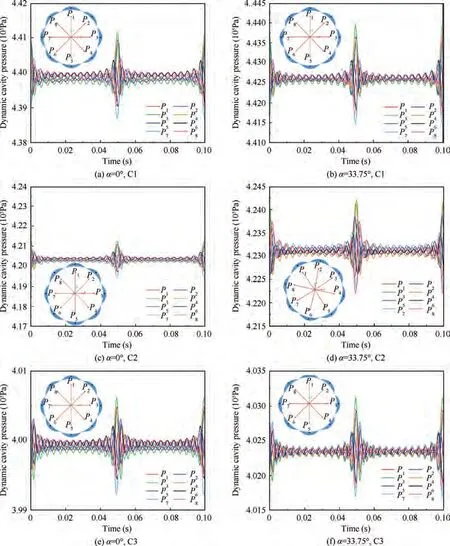
Fig. 15 Dynamic pressure in scallop cavity changes with time (X-direction excitation).
3.3.Effects of operation conditions and geometric parameters on flow details inside seal
To further figure out the detailed flow characteristics inside each seal cavity, this section presents the effective damping of each seal cavity and the seal force distribution under various boundary and geometry conditions.
Fig.17 shows the variation of effective damping of different seal cavities (C1-C9) versus the whirling frequency. The effective damping of the upstream cavities (C1-C3) of the scallop damper seal decreases with the increasing whirling frequency.While the effective damping of the downstream cavities (C4-C9) increases with the increasing whirling frequency. Overall,the effective damping of upstream seal cavity is greater than that of downstream seal cavity.
The rotor whirling in the seal makes the seal clearance change and produces the seal force acting on the rotor surface.The seal force can be decomposed into tangential and radial component forces. Under the transient condition, the tangential and radial component forces for various inlet pressures,preswirl ratios, rotational speeds, interlaced angles and cavity depths are extracted respectively. At this time, the rotor reaches the maximum positive position of the Y axis and moves clockwise to the positive X axis. The fluid excitation force vector diagram is made, and it is more intuitive to illustrate the influence of inlet pressure, preswirl ratio, rotational speed, interlaced angle and cavity depth on the seal force acting on the rotor surface.
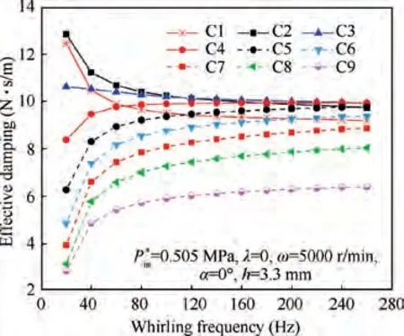
Fig.17 Effective damping vs whirling frequency at different seal cavities.
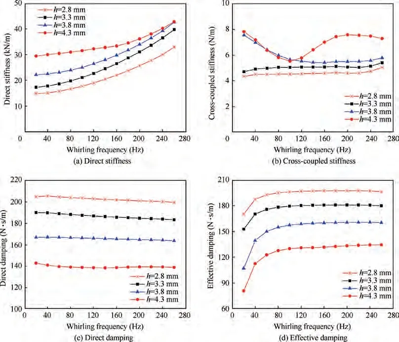
Fig. 16 Dynamic coefficients vs whirling frequency for different seal cavity depths (P*in = 0.505 MPa, λ = 0, ω = 5000 r/min,α = 33.75°).
Fig. 18 gives the radial force Fand tangential force Funder three different inlet pressures (P*= 0.303, 0.404,0.505 MPa). The radial and tangential force are opposite to the direction of the rotor whirling, which could suppress the rotor whirling. With the increase of inlet pressure, the magnitude of both Fand Fincrease. The resultant seal force F increases and deviates from the direction of rotor whirling,which is beneficial to suppressing the rotor whirling. Therefore,with the increase of the inlet pressure,the scallop damper seal shows more stable performance.
Fig.19 shows the pressure and seal force distribution under different preswirl ratios (λ = 0, 0.3, 0.5). The radial and tangential force under different inlet preswirl ratios are opposite to the direction of the rotor whirling. With the increase of the preswirl ratio, the magnitude of the Fand Fdecreases,and the resultant force F also decreases. As a result, the increase of preswirl ratio is not conducive to the suppression of rotor whirling.
Fig.20 shows the vector of the seal force acting on the rotor surface under different rotational speeds (ω = 5000, 6000,7000 r/min). The radial and tangential force under different rotational speeds are also opposite to the direction of the rotor whirling. With the increasing rotational speed, the magnitude of both Fand Falmost keep a constant,and the corresponding resultant force F nearly unchanged.Therefore,the effective damping at different rotational speeds is very close in the high frequency region, which is consistent with the trend shown in Fig. 12(d).

Fig. 18 Static pressure and seal force distribution for different inlet pressures (Y-direction excitation, t = 0.1 s, C2).

Fig. 19 Static pressure and seal force distribution for different preswirl ratios (Y-direction excitation, t = 0.1 s, C2).

Fig. 20 Static pressure and seal force distribution for different rotational speeds (Y-direction excitation, t = 0.1 s, C2).
Fig. 21 shows the seal force vector under different interlaced angles (α = 11.25°, 22.50°, 33.75°). The radial and tangential force under different interlaced angles are opposite to the whirling direction. For α = 33.75°, the magnitude of the seal force Fand Fare relatively large, and the ability of suppressing the rotor whirling is quite effective. On the contrary,for α = 22.50°, the magnitude of the seal force Fand Fare relatively small.
Fig. 22 shows the pressure contours and seal force vector under different cavity depths(h=2.8,3.3,3.8 mm).The radial force and the tangential force under different cavity depths are also opposite to the direction of the rotor whirling. Although the overall pressure in the seal cavity increases with increasing seal cavity depth, the pressure distributes more evenly. Therefore, the magnitude of the seal force Fand Fdecrease significantly with the increasing the seal cavity depth, and the resultant force F also decreases. Hence, with the increase of seal cavity depth, the seal stability is poor.
3.4. Leakage characteristics of scallop damper seal
Table 3 shows the leakage comparison of the scallop damper seal. The inlet pressure has a significant effect on the leakage of scallop damper seal,and the leakage flowrate decreases with the decreasing inlet pressure.Among them,the seal leakage at P*=0.303 MPa is reduced by 42.1%compared with that at P*= 0.505 MPa. The preswirl reduces the leakage of the scallop damper seal. For λ = 0.7, the leakage flowrate isreduced by 0.44% compared with the seal without preswirl.The influence of rotational speed on the seal leakage is relatively small, and the seal leakage decreases slightly with the increase of rotational speed. When adjacent seal cavities are interlaced at a certain angle,the leakage of scallop damper seal is lower than that of paralleling seal cavities. The amount of leakage at the interlaced angle α = 22.50° is reduced by approximately 2.11% compared with α = 0°. The leakage of the scallop damper seal decreases with the increase in the depth of the seal cavity,and the leakage of the seal cavity at a depth of h = 4.3 mm is about 3.73% less than that at a depth of h = 2.8 mm.
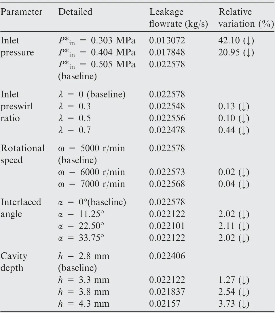
Table 3 Comparisons of leakage flowrate.

Fig. 21 Static pressure and seal force distribution for different interlaced angles (Y-direction excitation, t = 0.1 s, C2).

Fig. 22 Static pressure and seal force distribution for different cavity depths (Y-direction excitation, t = 0.1 s, C2).
4. Conclusions
This paper reports a comprehensive investigation on the rotordynamic performance of the scallop damper seal. A computational fluid dynamics method is employed to establish a full three-dimensional numerical model for the scallop damper seals. An identification method based on the multifrequencies elliptic whirling model is applied to obtain the dynamic force coefficients. The CFD model predicts the dynamic force coefficients for the seals operating under various inlet pressures, preswirl ratios, rotational speeds, interlaced angles, and cavity depths conditions. Several conclusions are summarized as follows.
(1) The baffle structure of the scallop damper seal can effectively obstruct the circumferential flow of fluid between two adjacent scallop-shaped small cavities. In scallop cavities, low speed regions are generated, and the circumferential velocity of the fluid decreases. Moreover,the fluid will be compressed or expanded to some extent in the independent scallop cavities, resulting in system damping, which is conducive to the stability of the seal system.
(2) The direct stiffness of the scallop damper seal increases with the decreasing inlet pressure, the increasing rotational speed and cavity depth.Under different inlet preswirl ratios, the direct stiffness is negative, which is not conducive to the static stability of the seal system. For α ≠0°, the scallop damper seal all show positive direct stiffness,which significantly improves the static stability of the system.
(3) The effective damping of the scallop damper seal increases with the increasing inlet pressure,and increases with the decreasing preswirl ratio and rotational speed.The inlet pressure has a significant influence on the effective damping.The effective damping of the inlet pressure P*=0.505 MPa is about 83%higher than that of the P*=0.303 MPa.There is an optimal interlaced angle for interlaced scallop damper seal to maximize the effective damping and the system stability(the optimal interlaced angle calculated in this paper is α = 33.75°), and the effective damping at α = 33.75° is about 111%-121%of that at α=0°.The effective damping increases with the decreasing cavity depth. The effective damping at h = 2.8 mm is about 146%-211% of that at h = 4.3 mm.
(4) The leakage of the scallop damper seal is significantly reduced with decreasing inlet pressure.The preswirl will reduce the leakage of the seal, and the rotational speed has a slight effect on the leakage of the seal.The leakage of the scallop damper seal decreases with increasing seal cavity depth. The leakage for an interlaced angle of 22.50°is about 2.11%lower than that at 0°.The leakage for the seal cavity depth of 4.3 mm is reduced by about 3.73% compared with that of 2.8 mm.
The authors declare that they have no known competing financial interests or personal relationships that could have appeared to influence the work reported in this paper.
The author thanks the anonymous reviewers for their critical and constructive review of the manuscript. This study was co-supported by the National Natural Science Foundation of China (No. 51875361) and the Natural Science Foundation of Shanghai, China (No.20ZR1439200).
