
Vector deflection stability control of aero-engine based on linear active disturbance rejection
2022-07-30 09:39:42ChangpengCAIYerongPENGQiangangZHENGHaiboZHANG
Chinese Journal of Aeronautics 2022年8期
Changpeng CAI, Yerong PENG, Qiangang ZHENG, Haibo ZHANG
College of Energy and Power Engineering, Nanjing University of Aeronautics and Astronautics, Nanjing 210016, China
KEYWORDS Actuator load variation;Axisymmetric Vectoring Exhaust Nozzle (AVEN);Engine performance;Linear Active Disturbance Rejection Control(LADRC);Vector deflection
Abstract Aimed at the problem of instability in engine control caused by vector deflection in experiment of turbofan engines with Axisymmetric Vectoring Exhaust Nozzle (AVEN), a vector deflection stability control method of aero-engine based on Linear Active Disturbance Rejection Control (LADRC) is proposed. Firstly, based on CFD numerical simulation,aerodynamic performance model of AVEN is established, and the aerodynamic load change rule of the nozzle throat area actuator during vector deflection is revealed. Subsequently, the integrated model of AVEN/-turbofan engine is established by Simulink/AMESim co-simulation. Finally,the nozzle throat area control loop based on LADRC is designed. The simulation results show that the integrated model can reflect the influence of vector deflection on the stability of the control system. The accuracy comparison between the fan rotor speed and the test data during vector deflection is larger than 1%, indicating a high degree of confidence. Compared with the conventional PID control, the designed LADRC control loop reduces the speed of the low-pressure rotor during vector deflection by 70%, which effectively improves the control stability of the vector deflection. Meanwhile, the fuel flow ratechange during the vector deflection process is smaller and more economical, which provides an important reference for engineering applications.
1. Introduction
Thrust vectoring technology has the advantages of improving fighter short-range air combat capabilities, improving deployment adaptability, improving flight safety, and optimizing platform aerodynamic stealth characteristics.As the core technology that supports the cross-generational development of fighter technology and capabilities,AVEN technology is a key way to realize thrust vectoring, and also one of the research hotspots in the field of thrust vectoring.
Originated from the research projects of Multi-Axis Thrust-Vectoring (MATV) and Advanced Control Technology for Integrated Vehicles (ACTIVE) proposed by the United States in the 1980 s and 1990 s for thrust vectoring test,AVEN technology carried out the flight demonstration verification of F-16 and F-15 verification aircraft.At the Zhuhai Air Show in 2018, the J-10B axisymmetric thrust vector verification aircraft carried out a series of post-stall maneuver flight demonstrations,showing a huge breakthrough in the engineering application of thrust vectoring technology.In the academic field,scholars focused more on the numerical simulation of the flow characteristics of the vectoring nozzle,choosing different turbulence modelsto study the flow characteristics of the vectoring nozzle and establishing a mathematical model of its aerodynamic performance.As the key component of the engine,the performance change of the vectoring nozzle will inevitably affect the working state of the engine,which leads to the instability of the vector deflection control in engineering experiment.However,there are few studies on integrated modeling of vectoring nozzle/engine and vector deflection stability control. Refs. 19-21 established a mathematical model of turbofan engine with vectoring nozzle, and studied the influence of vector deflection on engine performance under open-loop condition. Based on numerical simulation, Du et al. proposed an effective throat adjustment methodby providing more accurate input for the vectoring nozzle control system, to improve the control accuracy and provide a reference for the working state adjustment of the thrust vectoring engine. Li et al.established a miniature turbojet vector propulsion system model by combining experimental data and mechanism models.However,in practical engineering,the closed-loop control method is used for vector deflection, and the actual working conditions of the engine are complex. The aerodynamic load of the vector deflection actuator system changes sharply during the vector deflection, which further affects the stability control of the vector deflection. Therefore, the reference value of Quand Duet al.’s work is limited, and the model based on the micro-turbojet test data adopted by Li et al.is difficult to meet the accuracy requirements.Therefore,it is of great significance to establish an integrated model of AVEN/turbofan engine based on the mechanism, and study the comprehensive stability control of vector deflection on the basis of this model.
Therefore, based on the CFD numerical simulation, the aerodynamic performance model of vectoring nozzle is established,the analysis method of actuator pneumatic load is proposed,and the actuator model of nozzle throat A,exit section Aactuation system is also presented. Moreover, based on Simulink/AMESim co-simulation, a comprehensive model of AVEN/turbofan engine is established. Besides, aiming at the control instability of the traditional vector deflection PID method, the LADRC methodis employed to control the throat area loop, which realizes the fast, smooth and stable transition control of the vector deflection.
2. Aerodynamic performance calculation of AVEN
The two-dimensional geometric structure of the AVEN matching the engine model is shown in Fig. 1. Land Lare the length of the nozzle convergent and divergent flap, respectively. R, Rand Rare the inlet section, throat section and outlet section radius of the nozzle, respectively. The corresponding grid division is shown in Fig. 2.
The research on 3D vector deflection simulation of the AVEN is relatively mature.Luo et al.have studied the internal flow characteristics of axisymmetric nozzle calculated by different turbulence models, and obtained the conclusion that the numerical simulation accuracy of S-A equation model is the highest through comparative analysis with experimental data.

Fig. 1 Axisymmetric vectoring nozzle structure diagram.
Fig. 2 Mesh generation.
Therefore, based on the commercial CFD calculation software FLUENT, this paper selects the S-A turbulence model.The inlet boundary condition is pressure inlet, and the outlet boundary condition is pressure outlet.The relevant parameters are determined by the engine model under different flight conditions.
The nozzle outlet flow rate ˙mis calculated by the FLUENT post-processing module, and the nozzle thrust calculation formula is as follows:

where Fis the ideal thrust when the nozzle is fully expanded.
3. Actuation system model
3.1. Load characteristic modeling of nozzle throat area(A8)actuator
The force acting on the actuator of the AVEN is shown in the Fig. 3. From the functional point of view, the actuator can be divided into Aactuator system and Aactuator system. Aactuator system is composed of Aactuator,Aadjusting ring,cam pair, convergent flap ED, convergent sealing flap, etc.The output displacement of Aactuator is synchronized by Aadjusting ring; and the horizontal displacement is transformed into the rotation of convergent flap section by the action of cam pair,so as to change the throat area A.Aactuator system includes Aactuator, Asteering adjusting ring,pull rod AB, divergent flap DP, divergent sealing flap, etc.When the displacement of each actuator is not synchronous,the Asteering control ring deflects,and then drives the divergent flap on the other side of each pull rod to deflect on the basis of Athroat area, which drives the changes of Across-sectional area and thrust vector direction.
The force system of the Aregulating system acting on the convergent flap is a plane force system.The forces on the convergent flap are: the aerodynamic force of the convergent flap P, the force of the divergent flap on the convergent flap T,and the force of the Aadjusting ring on the convergent flap N.
The aerodynamic force of the convergent flap is:
The upper limit of integration Lis the length of the convergent flap. P(x) is the aerodynamic load distribution along with the convergent flap calculated and solved by vector deflection CFD. S(x) is the area distribution along the convergent flap.Considering that the aerodynamic load acting on the convergent sealing flap is transmitted to the convergent flap through the overlap between the sealing flap and the convergent flap,the load of the sealing flap is calculated by increasing the area of the convergent flap. The convergent flap can be approximated as an isosceles trapezoid, and its area integral formula is:
Fig. 3 Force analysis of AVEN actuation system.
The axial component of the force on the Aadjusting ring is balanced by the output load of the Aactuator.Assuming that the Aactuator system is driven by six Aactuators,the output load force of each actuator is:

3.2. A8 actuator modeling
Based on the vector deflection characteristics of the previous section,a simplified model of the Aactuator including electromagnetic directional valve, hydraulic actuator, displacement sensor, external load force model, PID controller and other structures is established based on the AMESim. The interface of the FMU(Functional Mock-up Unit) is inserted, the input parameter of the Aactuator is set as the displacement command and the external load force, and the output parameter as the displacement sensor feedback displacement. The AMESim model is shown in Fig.4.To establish the actuator model that can be used for vector deflection co-simulation on the Simulink platform, we export it in the form of FMU.
3.3. Introduction of A9 actuation system model
The Aactuation system is driven by three Aactuation cylinders, and the spatial arrangement of the three actuation cylinders is shown in Fig. 5. The simplified structure of Acontrol loop is shown in Fig. 6. The open-loop control method is adopted for Acontrol loop, which is mainly composed of AVEN spatial kinematics model and Aactuator system.The A, Aarea commands calculated by the Acontroller and vector deflection angle α are input into the AVEN space kinematics model.In this module,the displacement commands of the three Aactuators used to drive the vector deflection are calculated and transmitted to the Aactuator system. The three Aactuators act according to the input displacement commands, so as to realize the change of Across-sectional area and vector deflection.
The modeling process of AVEN spatial kinematic model which is not introduced in this paper, has been described in detail in Ref. 29. The function of the model is to calculate the three displacement commands of Aactuator needed to realize the vector deflection and the change of Asection area through the input A, Aarea and vector deflection angle α commands.
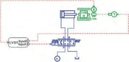
Fig. 4 FMU structure diagram of actuator.

Fig. 5 A9 actuator arrangement.
The Aactuation system is composed of three Aactuators.The calculation method of the pneumatic load force of the Aactuator is shown in Ref. 27. The model of the Aactuator is basically the same as that of the Aactuator shown in Fig. 4,which will not be repeated here.
4. AVEN/turbofan engine integrated model
The research object of this paper is a two axis hybrid turbofan engine with axisymmetric vectoring nozzle,and the basic structure is shown in Fig. 7. The steady-state component level model of the engine is established by Newton Raphson iterative method, which consists of high and low pressure rotor power balance, high and low pressure turbine inlet flow balance, internal and external culvert outlet static pressure balance and nozzle throat total pressure balance. When the engine working point changes, the flow and pressure balance equations are the same as the steady state, but the power changes. The original power balance equation is changed to the rotor dynamics equation, and the iterative method uses the one pass algorithm.
The effect of vector deflection on engine performance is mainly reflected in the change of effective throat area and nozzle thrust coefficient. The vector deflection will cause the nozzle throat tilt to reduce the effective throat area, which will affect the working state of the engine, and the change of the thrust coefficient will lead to the change of the engine output thrust. Therefore, the effective throat area coefficient Cis defined as:


Fig. 6 Control loop of A9 actuator system.
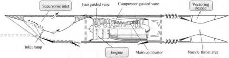
Fig. 7 Engine structure diagram.

where Cis the thrust coefficient of the nozzle in the deflected state under different working conditions,and Cis the reference thrust coefficient in the non deflected state.

When vector deflection, the calculation formula of engine vector total thrust is:where vis the airflow velocity at the outlet of the nozzle, ˙mis the air flow at the engine inlet, vis the airflow velocity at the engine inlet.
When the vector deflects, the effective throat area coefficient Cchanges,which changes the common working equation,while the relative thrust coefficient Cchanges cause the tail nozzle thrust to drop. The two work together to affect the change of engine performance. Combined with the Section 3 vectoring nozzle actuator model, the comprehensive simulation model as shown in Fig. 8 is established to reveal the dynamic influence of vector deflection on engine working state and A,Aactuator,so as to realize the high confidence simulation of vector deflection.
5. Design of linear active disturbance rejection controller for vector deflection A8 control loop
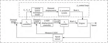
Fig. 8 Structural block diagram of vector deflection integrated model.
The conventional control loop of Athroat area generally adopts proportional-integral control, but for the throat area control of AVEN,the load on the inner wall of the convergent flap changes due to vector deflection, which causes the load change of the Aactuator. The load interference has a great influence on the control stability of servo return. The conventional PI control cannot meet the control target requirements,but the Linear Active Disturbance Rejection Control(LADRC) automatically compensates for the internal and external disturbances of the system through the linear state observation structure, which has stronger anti-disturbance ability, and simplifies the control parameter tuning process,which is more suitable for engineering applications.Therefore,this paper carries out the research on vector deflection stability control based on the comprehensive vector deflection model in Section 4.
The block diagram of LADRC control system adopted in this paper is shown in Fig. 9. The command set value r (lowpressure turbine speed command n) and control disturbance d are external signals in the control loop. Among them, the Tracking Differentiator (TD) arranges the transition process to avoid the sudden change of the controller input command,and the Linear Extended State Observer(LESO)is used to estimate the external disturbance d and the internal uncertainty of the system in real time. The output control signal u (nozzle throat area) and the object output y (low-pressure turbine speed) are the two inputs of LESO, and z, zand zare the outputs of LESO,both of which track the low-pressure turbine speed, the acceleration of low-pressure turbine speed and the generalized disturbance(external disturbance and internal disturbance). K, Kand bare controller parameters. eis the error between the speed command and the feedback speed.uis the control signal.
Despite a complex nonlinear system, the integrated engine model is generally regarded as a second-order system in the controller design in engineering. The object equation can be expressed as:

where y is the output variable, -a ˙y-by is the internal disturbance, w is the external disturbance, b is the control gain, and b ≈b. f=-a ˙y-by+w+(b-b)u is called generalized disturbance,which includes the internal nonlinear components of the system and the external disturbance.
By rewriting the object to the unit gain double integral control mode, the state space equation of the object can be described as follows:

where γ is the speed factor, which determines the tracking speed, h is the filtering factor, which determines the filtering effect, v(k) is the transition process that the plant can expect at time k, v(k) is the differential signal at time k, v(k) is the input signal at time k, and fis the nonlinear function as follows:
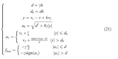
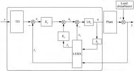
Fig. 9 LADRC control structure diagram.
The LESO equation is expressed as:
In conclusion, the parameters of LADRC controller need to be adjusted include controller bandwidth ω, observation speed coefficient K,observer bandwidth ωand control coefficient b. ωcan be determined by the adjustment time t. in general, tis 1-2 s in engineering. The larger ωis, the larger the system bandwidth is. The observation speed coefficient K is generally greater than 4/t,and the larger the K is,the faster the observation speed is and the larger the response bandwidth is. The observer bandwidth ωis approximately equal to(3-5)ω. The larger the observer bandwidth is, the larger the response bandwidth is, and the faster the system response speed is.The larger the controller coefficient b,the smaller the overshoot. By adjusting these four parameters online, the response speed and control quality of the vector deflection integrated model can meet the expected requirements. And the quantitative analysis of the robustness of the control method is shown in Ref. 35.
6. Vector deflection simulation and analysis
6.1. Aerodynamic performance simulation of vector deflection
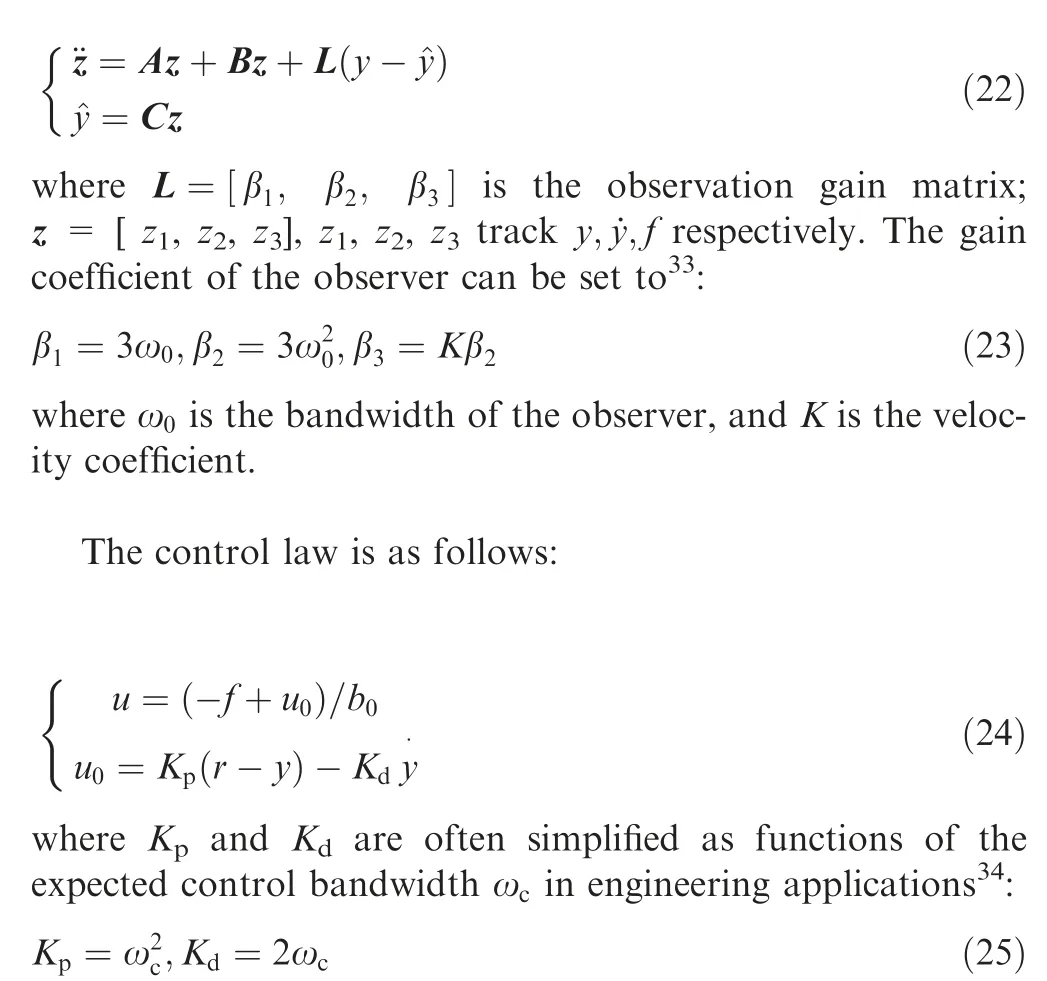
According to different flight conditions and different engine working conditions, the vector deflection aerodynamic models under different vector deflection angles are established, as shown in Figs. 10 and 11, where H is the flight height, Ma is the Mach number, PLA is the power level angle.
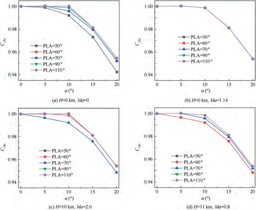
Fig. 10 Effective throat area coefficient.
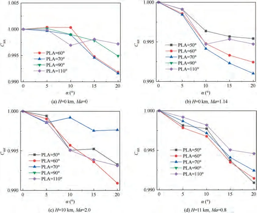
Fig. 11 Relative thrust coefficient.
It can be seen from Fig. 10 that the effective throat area coefficient of the engine decreases with the increase of the vector deflection angle.When the deflection angle is less than 10°,the vector deflection has little effect on the flow performance of the nozzle. When the deflection angle is greater than 10°, the flow performance of the nozzle decreases to a certain extent,and the changing trend of different flight conditions is basically the same. When the vector deflection angle is 20°, the nozzle flow capacity decreases by about 5%.Under the condition of H = 0 km, Ma = 0, the larger the engine state is, the stronger the flow ability of the nozzle at the same deflection angle.However,in other flight conditions and at the same vectoring angle, the change of engine state has little effect on the flow ability of nozzle.This is because the nozzle drop pressure ratio is at a high level under other flight conditions, and the change of engine state has relatively little influence on the nozzle drop pressure ratio. Moreover, the nozzle drop pressure ratio is one of the key factors affecting the nozzle flow ability,so the change of nozzle flow ability with the vector deflection angle is basically the same under different PLA.
It can be seen from Fig. 11 that vector deflection has little effect on the thrust coefficient of nozzle.Under different flight conditions and different engine states, the thrust coefficient decreases slightly with the increase of vector deflection angle.When vector deflection is 20°, the relative thrust coefficient of nozzle decreases by about 1%.
6.2. Simulation of actuator vector deflection
6.2.1. Vector deflection simulation of Aactuator
According to the CFD calculation results under different vector deflection states, the loading conditions of Aactuator under different vector deflection states are calculated.The corresponding simulation results are shown in Fig. 12.
Fig. 12 shows the simulation results of Aactuator load force under different engine working conditions and different vector deflection angles. It can be seen from Fig. 12 that with the increase of the vector deflection angle,the load force of Aactuator decreases continuously, which means that the load flow required to maintain the Aarea unchanged during the vector deflection decreases. However, the conventional servo loop control is still based on the load force of non vector deflection. Therefore, the original control gain is too large,resulting in the output load force cannot match the force state of Aactuator after deflection, which may lead to instability and jitter of Acontrol during vector deflection.
According to the above simulation results of Aactuator load force, the simulation of Aactuator vector deflection is carried out. When the Aactuator keeps the output 5 cm displacement command constant,input the vector deflection command shown in Fig. 13(a), Figs. 13(b) and (c) are the corresponding ground point and high-altitude point vector deflection Aactuator load commands. The response result of Aactuator is shown in Fig. 13(d).
It can be seen from the response results that with the increase of the vector deflection angle, the load force of the Aactuator will change to a certain extent, which will cause certain fluctuations in the Aactuator under the control of the constant displacement command(L). And the larger the
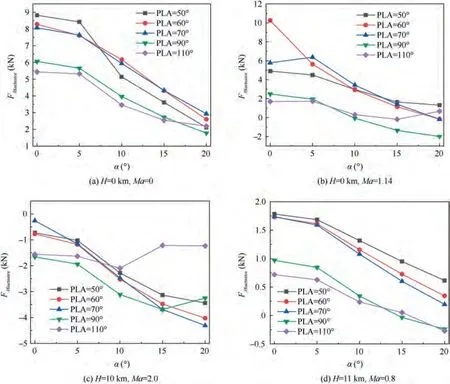
Fig. 12 Load force of A8 actuator with different states and different vector deflection angles.
vector deflection angle is, the more intense the change of Aactuator load force is, and the larger the change amplitude of actuator output displacement is. The load force of the Aactuator at high-altitude point has a smaller change than that at the ground point,ie.when the vector deflection angle is 20°,the output displacement amplitude of the actuator changes close to 1.6%. The simulation of actuator vector deflection verifies the analysis of the simulation results of Aactuator load characteristics in the previous section, and proves that the load variation of Aactuator during vector deflection will indeed affect the stability control of A.Therefore,it is of great significance to establish the Aactuator model which can reflect the load variation characteristics of vector deflection.
6.2.2. Vector deflection simulation of Aactuator
Given the vector deflection command of downward deflection as shown in Fig.13(a)in ground state and high-altitude cruise state respectively, the pneumatic load input of Aactuator is shown in Figs. 14(a) and (b). Due to the downward pitching deflection, according to the symmetry, the aerodynamic load and displacement responses of No. 2 and No. 3 Aactuators are the same.Different from the Aactuator,the aerodynamic load force of Aactuator in the opposite direction increases with the increase of the vector deflection angle,while the aerodynamic load force of Aactuator in the same direction remains unchanged or decreases slightly.The Aactuation system achieves vector deflection by increasing the load force of the actuator at the opposite position of the deflection direction to push the divergent section. The displacement response results of Aactuator are shown in Figs. 14(c) and (d).
Under different vector deflection commands, the Aactuator can basically achieve synchronous actuation, which can effectively ensure that the ratio of Across-sectional area to Across-sectional area remains unchanged in the process of vector deflection.
6.3. Vector deflection simulation of AVEN/turbofan engine integrated model
According to the actual test data of the engine with vectoring nozzle, the same vector deflection signal of 15° fast deflection and returning to the center is shown in Fig. 15(a). The results of comparison between the integrated model and the test data of high and low relative rotor speed responses in the ground interme diate state are shown in Figs. 15(b) and (c).
It can be seen from Figs.15(b)and(c)that when the vector deflection angle increases, the low-pressure rotor speed (N)will decrease to a certain extent. When the vector deflection returns to the middle, the low-pressure rotor speed will increase to a certain extent compared with the non-deflection state, and the vector deflection has little effect on the highpressure rotor speed (N). The integrated model established in this paper can effectively simulate the change of engine performance parameters in the process of vector deflection.It can be seen from Fig. 15(d) that the maximum error of relative speed change of low-pressure rotor (e) is 1%, while that of high-pressure rotor (e) is less than 0.3%, indicating that the integrated model has a high degree of confidence.
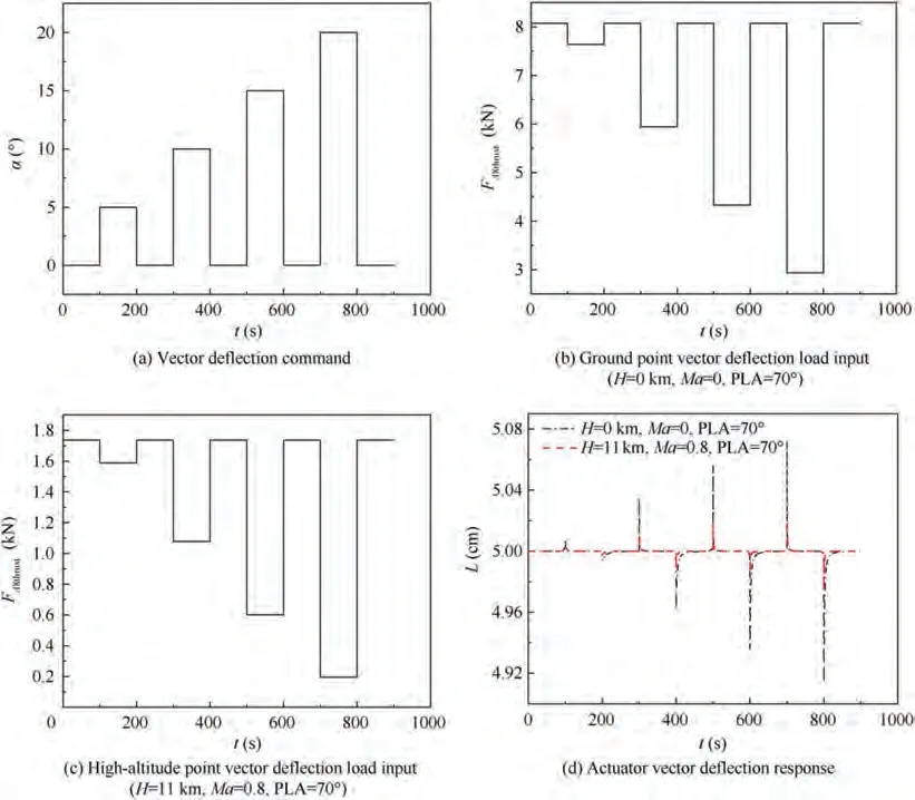
Fig. 13 Actuator vector deflection simulation.
6.4. Vector deflection control simulation based on LADRC
The simulation results of Section 6.3 vector deflection 15°show that the conventional Acontrol loop with PID control caused large fluctuation of low-pressure rotor speed during vector deflection, which seriously affects the control quality in the process of vector deflection. Therefore, this paper proposes an Aloop control method of vector deflection based on LADRC. The comparison of vector deflection response in the middle state of the ground is shown in Fig. 16. It can be seen from Fig. 16 that compared with the conventional PID control, LADRC control method can effectively reduce the variation range of low-pressure rotor speed in the process of vector deflection by about 70%and has faster response speed,which can effectively improve the control quality of lowpressure rotor speed and enhance the control stability of Aloop.
To further verify the robustness of LADRC controller, in the high-altitude cruise state of H = 11 km, Ma = 0.8, the simulation of 15° and 20° vector deflection as shown in Fig. 17 is carried out respectively, and the results are shown in Figs.18 and 19.The symbol‘‘-”in the Figs.18 and 19 indicates data normalization processing.
It can be seen from Fig.18 that the vector deflection is performed at the high-altitude cruise point with a rapid deflection of 15° and then back to the center. Compared with the traditional PID control, when LADRC control is used in Aloop,the engine thrust response is faster, the speed change range of low-pressure rotor is smaller,the fuel flow(W)change range is smaller in the deflection process,resulting in better economy,yet larger change range of AThe ratio of A/Ais constant during the vector deflection,so the trend of Ais basically consistent with that of A. The fan surge margin (SM) decreases with the increase of vector deflection angle,while the compressor surge margin (SM) increases with the increase of vector deflection angle. When the vector deflection is 15°, the engine thrust increases slightly. This is because the effective throat area decreases after the nozzle is deflected,and the engine drop pressure ratio decreases,resulting in an instantaneous increase in the total temperature and pressure of the engine nozzle inlet during the deflection process, which causes engine thrust fluctuations. However, it can be seen from Fig. 18(h) that the engine thrust change range of LADRC control method is smaller during vector deflection,which is conducive to keeping the engine working state stable during vector deflection.
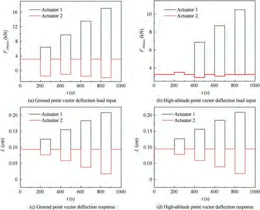
Fig. 14 Vector deflection simulation of A9 actuator.
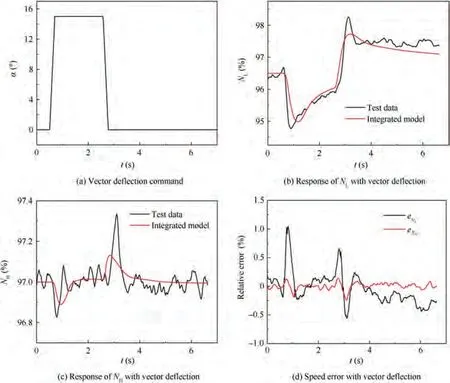
Fig. 15 Integrated model vector deflection simulation results.
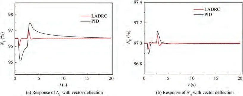
Fig. 16 Simulation comparison of ground point vector deflection with different control methods.

Fig. 17 Vector deflection command.
It can be seen from Fig. 19 that the trend of the vector deflection 20° simulation result is basically the same as the 15° simulation result. But the speed variation range of low pressure rotor is larger when the vector deflection is 20°. It can also reflect that the use of LADRC control in the Aloop can effectively improve the stability of the engine performance during vector deflection.
7. Conclusions
This paper concentrates on the stability control of vector deflection based on the integrated model of AVEN/turbofan engine.With the analysis and simulation results,the following conclusions could be drawn:
(1) When the vector deflection is applied, the load force of Aactuator decreases greatly with the increase of the vector deflection angle. When the vector deflection is 20°, the output displacement of the actuator will fluctuate by 1.6%, which could affect the stability control of A. Aactuator only affects the adjustment of Across-sectional area, and has little influence on engine performance parameters when the vector deflection occurs.
(2) Compared with the experimental data of vector deflection, the maximum error of the established integrated model is less than 1%, which indicates that the established integrated model has high confidence and can effectively simulate the changes of engine parameters in the process of actual vector deflection.
(3) During the vector deflection,adopting the LADRC control method, the low-pressure rotor speed change range is reduced by 70% compared with the traditional PID control, which can effectively ensure the stable control of the vector deflection. Furthermore, the fuel flow rate changes less during the vector deflection process, which is more economical.
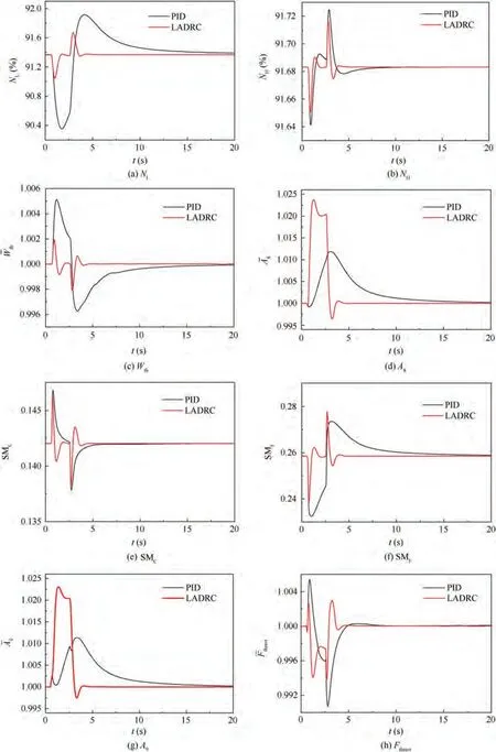
Fig. 18 Simulation of 15° vector deflection in high-altitude cruise state.
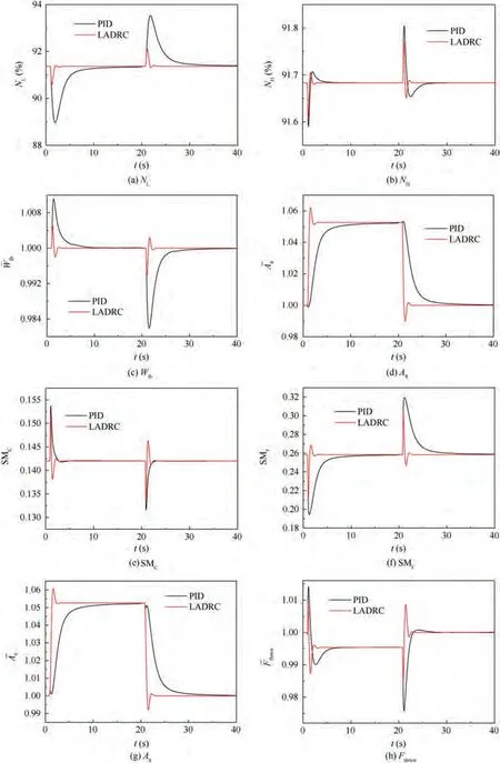
Fig. 19 Simulation of 20° vector deflection in high-altitude cruise state.
The authors declare that they have no known competing financial interests or personal relationships that could have appeared to influence the work reported in this paper.
This study was supported in part by the National Science and Technology Major Project, China (No. 2017-V-0004-0054), in part by the Research on the Basic Problem of Intelligent Aeroengine, China (No. 2017-JCJQ-ZD-047-21), in part by the Fundamental Research Funds for the Central Universities,China (No. NZ2020002), in part by the National Natural Science Foundation of China (No. 51906102).