Influence of sub boundary layer vortex generator height and attack angle on cross-flows in the hub region of compressors
Ho FU, Ling ZHOU,*, Lucheng JI
a School of Aerospace Engineering, Beijing Institute of Technology, Beijing 100081, China
b Institute for Aero Engine, Tsinghua University, Beijing 100084, China
KEYWORDS Compressors;Corner separation;Cross-flow;Flat plate;Vortex generator
Abstract It has been recently shown that Sub Boundary layer Vortex Generator(SBVG,abbreviated as VG hereafter) can suppress the Cross-Flow (CF), and therefore, can eliminate corner separation and increase aerodynamic loading when installed on the end wall inside middle-load compressor passages. However, when VGs are applied in high-load compressors, it is difficult to achieve ideal results. This is because the definition of the VG attack angle in the presence of CF in existing research is confusing,and the stronger CF in high-load compressors worsens the problem and results in an improper design and optimization range of VG attack angle.Therefore,this paper clarifies the definition of the VG attack angle in the presence of CF and reveals the CF controlling mechanism of VG on a flat plate. The differences in the flow phenomena around a VG both with and without CF are also studied.The numerical results show that a larger height or attack angle of the VG generates a greater CF suppression effect. However, the cross velocity increases when surmounting the primary vortex induced by the VG,except that this enhanced CF is less conspicuous for larger VG heights.Compared to the cases without CF,the VG suffers an additional loss because of the stronger separation and primary vortex loss caused by the CF.
1. Introduction
To achieve higher thrust-to-weight ratio,higher efficiency,and lower fuel consumption in aeroengines, it is necessary to reduce the number of compressor stages and increase the single-stage pressure ratio in the compressor. To date, with the development of aviation technologies, high-load compressors can efficiently diffuse the flow over the middle 60%-80%of the span.Thus, the specific flow phenomena in other parts of the compressor are the keys to further improve the performance of high-load compressors.For example,Sun et al.further modified and optimized the Boundary Layer(BL)suction layout for a large-scale blockage on the root of a super-highload transonic stator,which effectively eliminated the blockage caused by low-energy flow. The axial sweep blade technique has been used to reduce the shock wave loss at the tip of the leading edge of a high-load compressor and further increase the pressure ratio.However, suppressing the corner separation has encountered significant difficulties.The main factors that cause corner separation are: (A) the intersection of the BLs on the blade and the endwall under an adverse pressure gradient,and(B)Cross-Flow(CF)caused by the circumferential pressure gradient.For BL intersections, Ji et al.developed the Blended Blade and Endwall (BBEW) technique and applied it to Rotor 67, which not only nearly eliminated the corner separation but also improved the performance over the entire operating range. They also discussed the differences between the BBEW and the blade rounding in detail.However, it was still difficult to control the CF.
Researchers have developed a variety of promising techniques to weaken the influence of CF, such as nonaxisymmetric endwalls and Sub Boundary layer Vortex Generators (SBVGs). Non-axisymmetric endwalls can generate an‘‘aerodynamic separator” to suppress the CF and improve the compressor performance.However, applying them only to the hub of a transonic stator channel may aggravate separations near the blade tip and lead to performance degradations under the off-design operating conditions, though it can suppress the corner separation at the design operating point.Thus, non-axisymmetric endwalls need to be applied to the shroud to improve this situation.As a result, SBVGs have been considered as alternative effective methods.
As early as the middle of the 20th century, Taylorproposed the concept of a Conventional Vortex Generator(CVG) and used it to successfully delay the BL separation of the plane wing.Since then,researchers in the outflow field have strongly considered CVGs,finding they can increase the lift of the wing by delaying the BL separation,adjust the vibration characteristics of the wing at transonic speeds,reduce the rear body drag of the aircraft fuselage,and suppress shock-BL interactions,etc.In the meantime,SBVG,which is defined as‘‘the generators with a device height between 10%and 50%of the BL thickness”,are proved to be nearly as efficient as the CVG,whose height is on the order of the BL thickness.The development prospects of SBVG (hereinafter referred to as VG)has led researchers in the internal flow field to apply it to compressors. Gamerdinger and Shreeveinstalled VGs on the suction surface of a transonic cascade to suppress shock-BL interactions but with an increased loss.Hergt et al.installed VGs upstream of the leading edge of a cascade to control CF and the horseshoe vortex, which reduced the total pressure loss by 9%, while also extending the stall boundary.Ma et al.combined VGs and BL suction,which transformed the corner separation into a trailing edge separation.Diaa et al.made the same attempt with a variety of VG types and showed that CF can be effectively suppressed, but the total pressure loss may sometimes increase or the diffusion factor may decrease. To date, attempts to install VGs on the suction side of the compressor blades have still not achieved ideal results,and the gap between the rows in a real high-load compressor is usually too small to contain VGs. Therefore, Li and Jiapplied VGs to the endwall inside a middle-load NACA 65 cascade passage, which successfully suppressed CF and weakened the corner separation, as shown in Fig. 1, in which Cis the static pressure coefficient.
Based on the application prospects of controlling CF,there have been attempts to apply VGs in the passages of the last stage stator of high-load compressors, but ideal results have not yet been achieved.The reason is likely related to the strong CF near the hub in the passage,but this needs to be approved.However, most existing research on flow phenomena around VGs and the associated mechanism is limited to cases without CF and little research has considered cases with CF.Therefore,this paper focuses on the CF controlling mechanism of VGs.The similarities and differences between the flow phenomena around VGs under CF to those without CF are also analyzed in order to study the influences of the CF on the operating conditions of the VG. The mechanisms are also analyzed to provide a reference for VGs to be applied in CF control for high-load compressor passages.
2. Numerical methods
2.1. Computational domain and mesh
The ICEM CFD and ANSYS CFX are adopted to generate the mesh and execute the steady RANS simulations.To verify the accuracy of the numerical method,the computational configuration is set to be the same as the experiment setup in Ref., where a rectangular VG is installed on a flat plate. As shown in Fig. 2, the domain is 300 mm wide, 140 mm high,and 1000 mm long.The dimensions of the VG are defined with a length of 7 times its height(h=7 mm),which corresponds to 0.2 times the inlet BL thickness δ(35 mm).The VG attack angle (α) is traditionally defined as the angle between the VG direction vector l and the free stream direction, and the VG stagger angle β is between the l and the x-axis. Without CF,α is the same as β,so α is used to distinguish the operating conditions of the VG for coherence in this section. The trailing edge of the VG is fixed at 100 mm downstream of the inlet to ensure that the results are comparable when α is changed.The location of the measurement stations as represented with Δx downstream of the VG trailing edge(x = Δx + 100 mm) is coincident with the experiments in Ref..
Verification of the mesh resolution is performed with three different meshes: a coarse mesh (4.06 million nodes), a standard mesh (5.88 million nodes), and a fine mesh (7.68 million nodes). The near-wall spacing of all three meshes is 1 μm,which results in ybeing maintained at approximately 1 and not exceeding 3. As shown in Fig. 3, the mesh contains an O-block around the VG and an H-block downstream of the VG.
2.2. Computational configuration
To obtain the inlet Boundary Condition (BC), the flat plate without VG or CF is calculated first for a velocity profile with a 35 mm BL height and 34 m/s free stream velocity (same as the experiment in Ref.), which is imported to the inlet BC for mesh verification. For all simulation cases, the inlet temperature Tis 288.15 K and the outlet pressure Pis 101325 Pa; the period BC is adopted at the broadsides of the calculation domain with an opening condition at the top. The turbulence model is the Shear Stress Transport (SST) model with an inlet turbulence intensity of 5%.

Fig. 1 VGs on hub inside compressor cascade to suppress CF.28
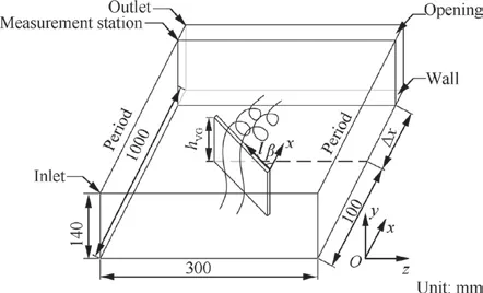
Fig. 2 Schematic diagram of calculation model.
2.3. Verification
The CFD results of the peak vorticity ωfor the three meshes and the experimental resultsare shown in Fig. 4.When Δx/δ≥2, the relatively coarser local grids than those near the VG lead to a larger numerical dissipation, and cause the numerical error of the three meshes to be relatively larger.However, in general all three meshes show coincident trends with the experiment. Though the fine mesh provides the best simulation accuracy, the differences between the results of the standard mesh and the fine mesh are small enough, and the standard mesh provides enough simulation accuracy. If the number of grids continues to increase, the benefit of numerical accuracy will get smaller,and the cost of calculation time will not be worthy enough.Therefore, the standard mesh with 5.88 million nodes is employed to perform the following simulations.The calculation results for VGs with attack angles of 10°,16°,and 23°are compared with the experimental results in Fig. 5. The computational peak vorticity of the VG with a 10°attack angle is slightly larger than the experimental results,while the other two CFD results are slightly smaller when Δx/δ= 2-4. The difference of the numerical over prediction or under prediction of the peak vorticity is also caused by the little differences of the local grid resolutions. As the same trend exists between the CFD and experimental results, the errors are considered negligible.
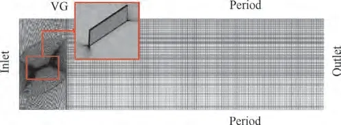
Fig. 3 Calculation mesh around VG (y+≈1, SST model).
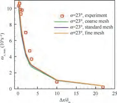
Fig. 4 Mesh independence validation.
3. CF setting
To investigate the weakening effects of the VG on the CF, a CF profile is added to the velocity inlet BC based on the above cases, which forms the velocity inlet BC with the CF. In the following sections, a typical CF profile in a real compressor is parameterized and the fitting result is added to the inlet velocity BC. Then a simple flat plate with a CF inlet without VGs is defined as the‘‘baseline case”,the basis of characterization of the CF suppression effect.
3.1. CF parameterization
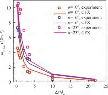
Fig. 5 Calculation method validation.
In the CFD results of the stator passage for a certain type of high-load compressor,the CF velocity profiles at 10 main positions on the hub are extracted and linearized based on the parameters in Ref.. Thus, the extracted CF profile including the velocity size and its spanwise position is multiplied with a modular coefficient in size and height so that the BL height is equal to 35 mm and the velocity in the Main Stream (MS)direction is equal to the Free Stream (FS) velocity Vof 34 m/s in Ref.. The CF profiles at the main positions in the static blade passage have a similar shape. Hence, the CF parameterization can be described from the five extracted main features:
(1) Maximum CF velocity near the wall V;
(2) Location of the maximum CF velocity near the wall y;
(3) Maximum reverse velocity V;
(4) Location of the maximum reverse velocity y;
(5) Location of the demarcation point of the CF and the reverse flow y.
It is seen that the VG mounted on the wall is inside the BL,so the CF peak described by Vand yis the critical parameter that determines the flow conditions around the VG. The reverse flow is outside the BL, which has a relatively indistinct influence on the flow. The statistics indicate that the ranges of the five CF features are:
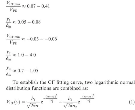
The strongest CF curve is fit in the above expression for a distinct flow phenomenon. The fitting results are shown in Fig. 6. The curve fitting coefficients are: b= 68.11,σ= 1.956, μ= - 5.869, b= 11.73, σ= 0.6971,μ= - 3.17.
Therefore, the CF profile is:

3.2. Velocity inlet BC with CF

3.3. Baseline case and CF decay
As the period BCs are set at the broadsides of the calculation domain,there are no pressure gradients in the transverse direction (z-axis); thus, the CF decays gradually along the MS direction (x-axis), as shown in Fig. 8. Therefore, a simple flat plate with a CF inlet without VGs, called the ‘‘baseline case”,is calculated. The effects of the VG on CF are evaluated through a comparison with the baseline case. Fig. 9 illustrates the decay of the CF peak in the baseline case, which indicates that the Vdecreases and its spanwise location yincreases at greater flow distances.However,at the VG leading edge location, Vdecreases by only 2%, and yincreases by only 6.4%δcompared with their values at the inlet,which are considered negligible. After an overall consideration, it is decided that the cross-section which cuts the inlet CF peak,and is perpendicular to the spanwise direction (y-axis) located at yat the inlet(y/δ=0.0814,y=2.85 mm),is defined as the ‘‘CF reference plane.” The cases with a VG are compared with the baseline case and the changes in Vas averaged in the transverse direction (z-axis) on the CF reference plane are calculated to characterize the weakening extent of CF.
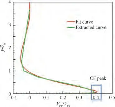
Fig. 6 Fitting results of CF profile.
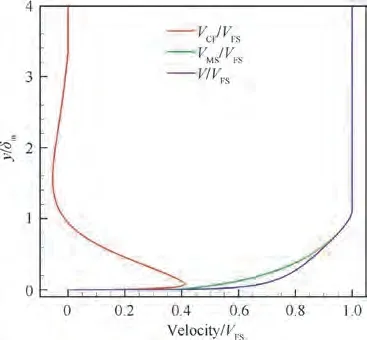
Fig. 7 Inlet velocity profile.
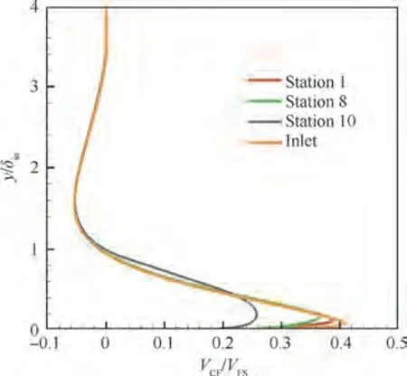
Fig. 8 CF decay along MS direction.
3.4. Definition of VG attack angle with CF
It is noted that after the introduction of the CF, the VG submerged in the BL causes the angle between the VG direction vector l and the incoming flow to change in the VG height range. Thus, the traditional definition of the VG attack angle is no longer appropriate. Therefore, the VG attack angle α is now defined as the angle between the VG direction vector l and the flow direction at the corresponding location of the top of the VG leading edge in the baseline case, as illustrated in Fig. 10. The VG defining α is plotted with dotted lines,expressing that this VG is hypothetical in the baseline case.This definition adopted the flow direction at the corresponding location in the baseline case, but not the flow direction in the VG case, because the VG will affect the upstream flow in subsonic condition. This definition is consistent with the traditional definition in the absence of CF.

Fig. 9 VCF,max and y1 distributions along MS direction.
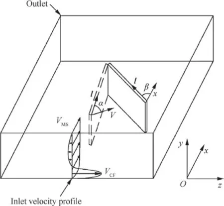
Fig. 10 Diagram of inlet velocity distribution and definition of VG attack angle with CF.
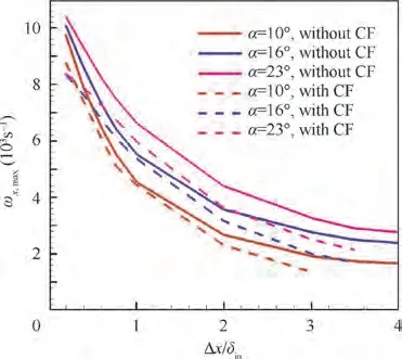
Fig. 11 ωx,max with and without CF.
The effects of the presence or absence of CF on ωas generated by the VG is exhibited in Fig. 11 using the VG attack angle definition above.Compared with the ωwithout CF,the ωin the presence of CF is slightly smaller but shows a coincident trend. Therefore, the above definition shows a considerable rationalization and ensures a comparison of cases with and without CF.
4. Results and discussion
4.1. Flow structure around VG
The flow structures around the VG with or without CF are illustrated in Fig.12.The 0.5δhigh VG at a 23°attack angle is taken as an example, including the vorticity in the xdirection,ωcontour map at the VG trailing edge,and streamlines dyed with Mach number (Ma). The main characteristics in the figure are the primary vortex downstream of the VG,the secondary vortex beside the VG,and the separation vortex on the leeward side of the VG leading edge. There is a similar flow structure around the VG both with and without CF.However, in the case with CF, the spanwise location of the CF peak is within the VG height range,leading to stronger secondary and separation vortices. This removes momentum from the incoming flow and results in a weaker and more diluted primary vortex.
4.2. Weakening effect of VG
Based on Ref.,the VG heights are set to 0.1δ,0.2δ,0.3δ,and 0.5δ, and the VG attack angles are set to 10°, 16°, and 23°. As a result, there are 12 cases both with and without CF,which is the basis to consider the effects of the VG height and attack angle on CF. The contour maps of Von the CF reference plane and the ωdistributions along the MS direction as generated by the VG under the influence of the CF are shown in Fig.13.It is seen that the primary vortex induced by the VG is equivalent to an ‘‘aerodynamic separator” (the same definition as Ref.), which directly hinders the downstream development of the CF peak within its height range.As the VG height and attack angle increase,the associated primary vortex becomes stronger,and its effect to weaken the CF increases. Moreover, this effect forms a CF weakening area over a certain opening angle γ on the CF reference plane, as shown in Fig.13(c).In this area,the primary vortex as induced by the VG due to its rotating direction(roughly along the MS)also forms a‘‘local reverse CF area”(purple region in Fig.13)on the CF reference plane,which grows with the increased VG height and attack angle. It is noted that VG heights of 0.1δ,0.2δ, and 0.3δare relatively low, which results in a lower position on the primary vortex core. Thus, the CF is obstructed at the primary vortex and strides over it before accelerating along its right side, which produces a dark green local CF acceleration region. With an increased VG height,this phenomenon is weakened, and the corresponding dark green local CF acceleration region gradually diminishes.
For VGs with a small attack angle and height, the secondary vortex nearly disappears. However, as the VG attack angle and height increase, the secondary vortex grows stronger. There are two reasons for this phenomenon. On the one hand, an increased VG attack angle leads directly to an increased angle between the VG direction l and the incoming flow ahead of the VG root.On the other hand,the VG attack angle is defined as between l and the direction of the flow ahead of the VG top. When there is CF, the CF peak causes the airflow angle of the incoming flow to increase sharply and then decrease along the spanwise direction(y-axis).At this time, if the VG height increases and the VG attack angle is maintained, the stagger angle β inevitably decreases. These together lead to an enlarged angle between l and the incoming flow near the VG root,which results in a strong secondary vortex. The secondary vortex also generates a ‘‘local reverse CF area” that can suppress the CF slightly, but it will dissipate rapidly and mix with the primary vortex, indicating it plays only a small role.
Fig. 14 illustrates the contour maps of the Von the CF reference plane and the ωdistributions under different VG heights and attack angles without CF. Compared with the cases in Fig. 13, the differences in Fig. 14 are because there is no CF at the inlet.First,the‘‘local reverse CF area”(purple region) becomes more prominent because the primary vortex induced by the VG is stronger when there is no CF.Moreover,the primary vortex dissipates more slowly along the flow due to the absence of CF,which is revealed by the longer dark purple regions in Fig. 14. Second, the secondary vortex is weakened or even completely gone when the VG height or attack angle is small because of the absence of the CF peak. Third,an opening angle γ is formed in the CF weakened area when the inflow is distorted by the CF, as shown in Fig. 13(c), but there is no such phenomenon without CF.Fourth,the conspicuous CF enhancement area in Fig.13 disappears from Fig.14 because there is no CF peak near the flat plate and no associated acceleration area that results from the CF striding over the primary vortex.
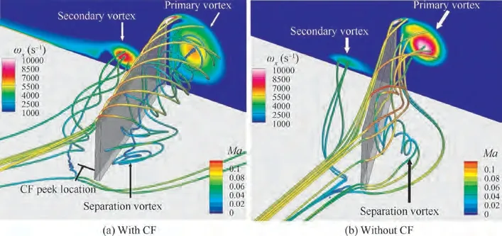
Fig. 12 Fundamental flow structure around VG.
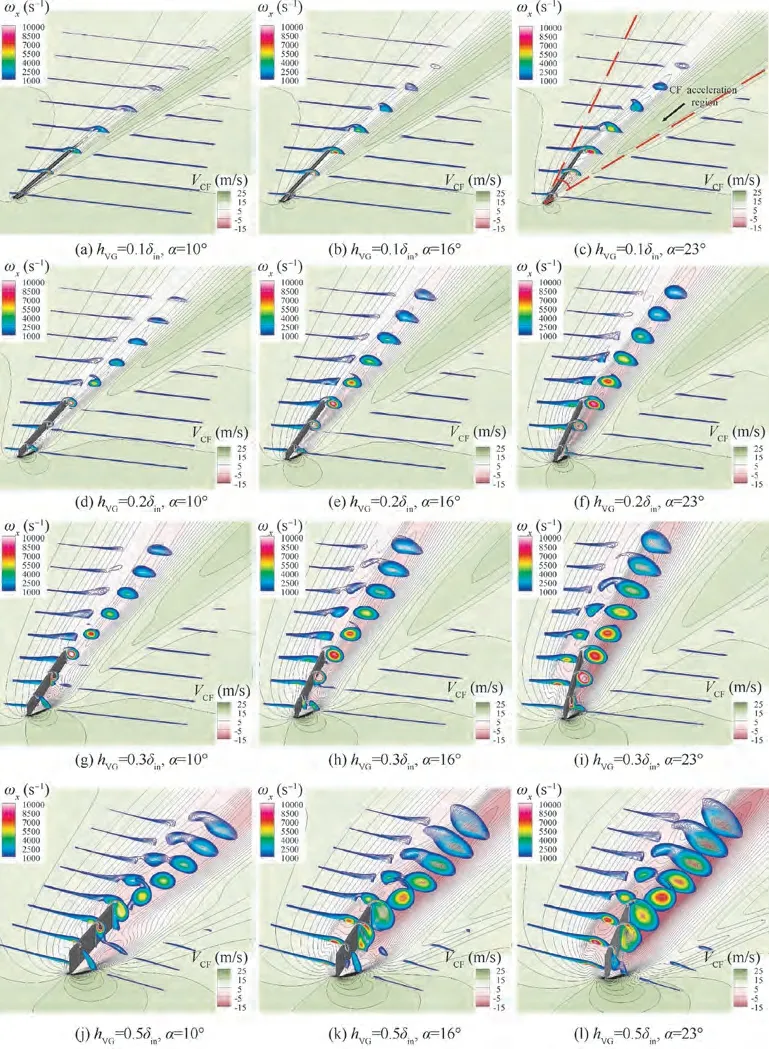
Fig. 13 Contour maps of VCF on CF reference plane and ωx distributions along MS direction with CF.
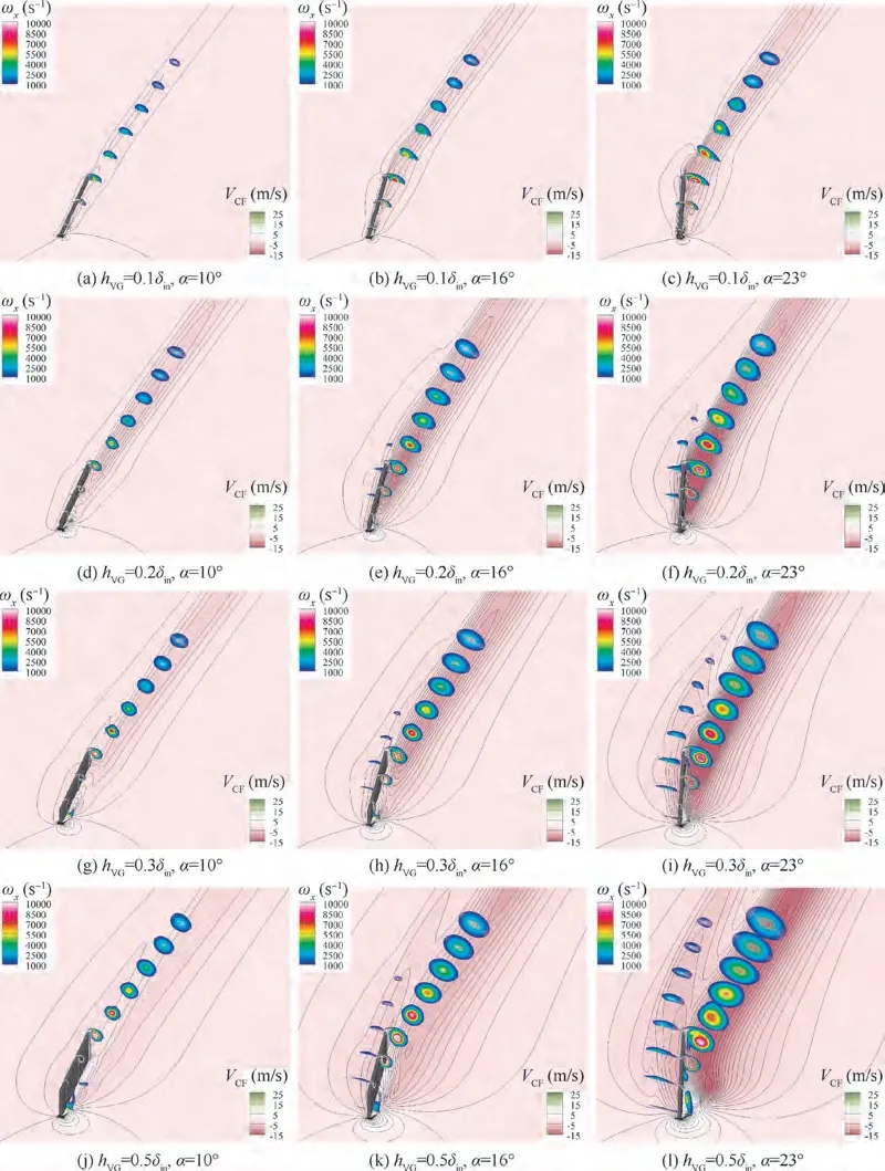
Fig. 14 Contour maps of VCF on CF reference plane and ωx distributions along MS direction without CF.
On the CF reference plane,the weakening effects of the VG with different heights and attack angles on the CF is shown in Fig. 15. The Von the ordinate axis is equal to the horizontally averaged V- Von the CF reference plane, where the Vis the CF velocity at the corresponding position in the baseline case. The same processing method is adopted for the cases without CF,so the Vpurely denotes the horizontally averaged ‘‘local reverse CF”generating effect. This statistical method characterizes the CF weakening over the entire transverse direction of the computational domain. As seen from Fig. 15, in cases with CF, a higher VG and larger attack angle give a greater weakening effect on the CF, and there is a similar conclusion for cases without CF. However, the ‘‘CF weakening effect” for VGs with CF is generally stronger than that without CF. This is because, as indicated by the above statistical method, the streamwise vortices induced by the VGs(including the primary and secondary vortices)not only produce a‘‘local reverse CF”on the reference plane but also strongly suppress the ‘‘incoming CF”.Although VGs can produce stronger primary vortices and form a stronger ‘‘local reverse CF” without the incoming CF, there is no incoming CF to be suppressed. In addition,when h=(0.3-0.5)δ, the dashed lines representing the cases with CF have a promontory in the range of Δx/δ= 0-3,which indicates that the CF weakening effect tends to increase quickly first before decreasing. This is because an increased VG height causes (A) the primary vortex to become stronger,and its maximum effect of generating the ‘‘local reverse CF”on the CF reference plane also strengthens; and (B) the distance between the primary vortex core and the CF reference plane grows, which needs the primary vortex to diffuse to make the most of its effect of ‘‘local reverse CF generating”.Combining the above two factors with the primary vortex diffusion process with CF, the maximum effect of generating a‘‘local reverse CF”on the CF reference plane becomes stronger and comes later in the process. Therefore, the expression for this mechanism is shown in Fig. 13 as a higher VG causes the darker center of the dark purple region and moves its location more downstream.In Fig.15,as the VG height increases,the higher the promontory is at the front of the dotted line,the more it shifts to the right. In contrast, the phenomenon of the solid curve that represents cases without CF is less obvious because there is no CF peak. This results in a weaker dissipation speed of the primary vortex and leads to a smoother effect on the generation of the ‘‘local reverse CF” along the CF reference plane.
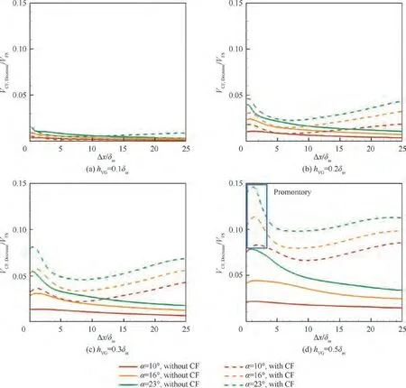
Fig. 15 Weakening effects of VGs on CF.
4.3. Migration path of primary vortex core
The inhibitory effects of the VG on CF are mainly achieved by inducing the primary vortex to block the CF peak. The CF peak is close to the wall along the spanwise direction, so the spanwise position of the primary vortex core is one of the key factors dictating whether it can effectively block CF. If the spanwise position of the primary vortex core is too high along the spanwise direction, it may not work immediately and needs to diffuse to attain a large enough radius downstream to directly hinder the CF peak near the wall. Fig. 17 shows the migration path of the primary vortex core along the spanwise direction. It is noted that the primary vortex for cases with CF attenuates faster than those without CF and entangles the shear flow in the BL with the CF, which becomes indistinguishable for Δx/δ>2. Therefore, only the range of Δx=(0.2-2)δis considered here. In all cases,the initial position of the primary vortex core is lightly lower than the VG height.When there is no incoming CF,the initial position of the vortex core increases with the attack angle for h= 0.1δ, but this pattern is reversed for h=(0.2-0.5)δ. As the primary vortex develops, its core rises gradually for h= 0.1δbut its spanwise position remains mostly stable for h=(0.2-0.5)δ. For cases with CF, the initial spanwise positions of the primary vortices are about the same as those without CF for h=(0.1-0.3)δ,but they are slightly lower for h=0.5δ.The primary vortex gradually migrates to the wall for h= 0.5δ, h= 0.3δ, and h= 0.2δand α=10°or α=16°;whereas it moves away from the wall for h=0.2δand α=23°,and h=0.1δand α=10°.For h=0.1δand α=16°or α=23°,it moves away from the wall first and then migrates back to it. Combining Fig. 13 and Fig.17 indicates that the spanwise position of the primary vortex will be low enough to hinder the CF peak near the wall when h=(0.1-0.5)δ.
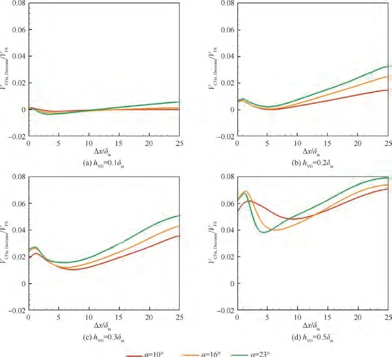
Fig. 16 Weakening effects of VGs on incoming CF.
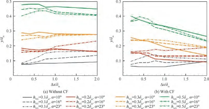
Fig. 17 Spanwise migration paths of primary vortex cores.
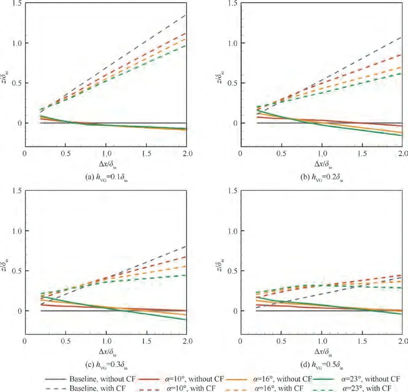
Fig. 18 Transverse migration paths of primary vortex cores and streamline direction at corresponding position of VG trailing edge in baseline case.
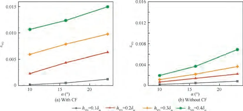
Fig. 19 Total pressure loss coefficient of VG.
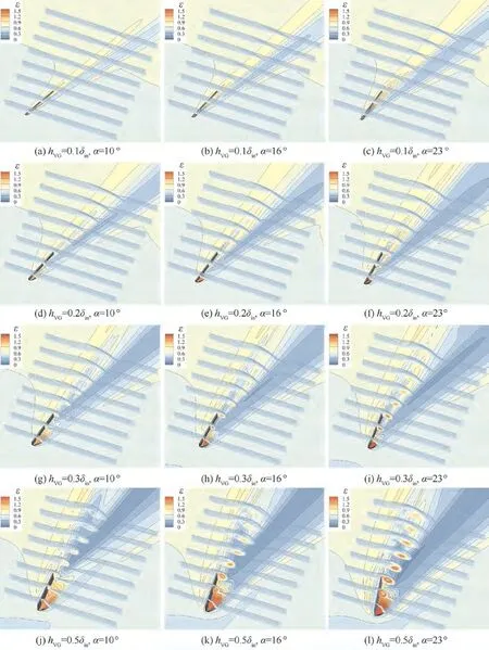
Fig. 20 Contour maps of ε along x-axis and on CF reference plane with CF.
In engineering applications,the CF flows from the pressure side of the blade to the suction side in a real compressor,so the primary vortex induced by VGs installed on the hub has a strong tendency to transport along the circumferential direction of the blade passage along with the CF. Thus, the vortex may hit against the blade suction side and interact with the corner separation of the blade suction side. Therefore, it is important to study the transverse migration path of the VG primary vortex with the incoming CF on the flat plate. The transverse migration paths of the primary vortex cores as induced by the VG at different heights and attack angles with or without CF and the streamline direction at the corresponding position of the VG trailing edge in the baseline case are summarized in Fig. 18. Without CF, the incoming free steam is in×direction and the VG primary vortex is generally transported with the local flow velocity but still deviates slightly to the direction of the VG direction vector l . Moreover, this trend strengthens with the VG attack angle.
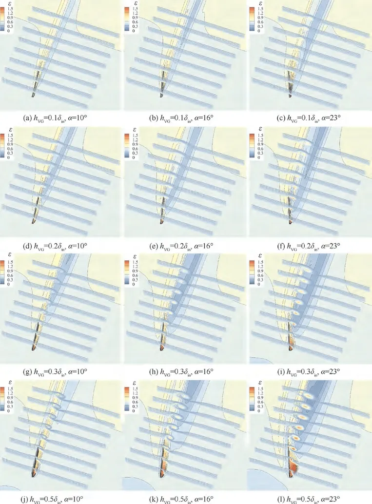
Fig. 21 Contour maps of ε along x-axis and on CF reference plane without CF.
The situation becomes a little more complicated with CF at the inlet. First, when the VG heights are the same, a greater attack angle leads to a larger angle between l and the incoming flow. This creates larger deviations in the path of the primary vortex from the streamline direction at the corresponding position in the baseline case. Second, at a fixed VG attack angle and increasing VG height, the l tends to rotate in the negative direction of the y-axis and the flow direction upstream of the top of the VG leading edge gradually shifts to the MS direction. These factors lead to a decreased transverse migration for the primary vortex with an increased VG height.Therefore,the primary vortex of the VG will generally migrate transversely due to CF. However, specific cases need to be considered to determine whether the VG vortices can stay away from the blade suction side in compressor blade passages.
4.4. Effects of VG on total pressure loss
Although VGs can restrain the CF to some extent, they also cause flow losses represented by the total pressure loss coefficient ε, which is defined as:

where p is the static pressure, p* is the stagnation pressure,Mrepresents the mass flow averaged parameter, Ais the area averaged parameter,and‘‘in”and‘‘out”are the inlet and outlet of the domain,respectively.The total pressure loss coefficient of the VG is obtained by subtracting the total pressure loss coefficient of the baseline case from that of cases with a VG as:

The total pressure loss coefficient of each VG εis shown in Fig. 19.
The Prince was more distracted than ever, and tried vainly to escape from the castle, by leaping from the roof into the clouds; but every time they caught him, and rolling softly up, brought him back to the place from which he started, so at last he gave up the attempt and waited with desperate patience for the return of Melinette
A higher VG and attack angle gives a greater VG loss.However,when the VG height is 20%or more of the BL thickness, the VG loss with CF is much larger than that without CF.Fig.20 and Fig.21 illustrate contour maps of the ε distribution along the x-axis and on the CF reference plane with and without CF,respectively.In both cases,the loss occurs primarily in the separation and primary vortices,while the loss of the secondary vortex is relatively small. While the secondary vortex is stronger in cases with CF, the associated loss is just slightly larger than those without CF. The primary and separation vortex losses with CF are stronger than those without CF.It is natural that the stronger separation vortex causes larger total pressure loss. Considering that the separation vortex is very close to the generation location of the primary vortex and the streamline crosses these two vortices clearly in Fig. 12, it is reasonable to believe that the stronger separation vortex also increases the primary vortex loss. Therefore, the main source of the increased εwith CF is from the primary and separation vortex.
5. Conclusions
The flow characteristics around VGs of different heights and attack angles with and without CF are studied,and the vorticity, migration paths, and total pressure loss of the VGs are summarized and compared. The conclusions are as follows:
(1) The flow field structure around the VG with CF is roughly the same as that around the VG without CF.whose main flow characteristics include primary, secondary, and separation vortices.
(2) When suppressing CF, the primary vortex plays the major role and is equivalent to an‘‘aerodynamic separator” that obstructs the CF peak in the scale of its spanwise range. With an increased VG height and attack angle, the vorticity of the primary vortex as generated by the VG strengthens and the CF suppression effect is enhanced.
(3) As the CF surmounts the primary vortex, it will step down and accelerate, which slightly enhances the local CF.With an increased VG height,the spanwise position of the primary vortex core rises, and the acceleration effect of the local CF surrounding the primary vortex is weakened.
(4) The initial position of the primary vortex core is slightly lower than the VG height and fluctuates slightly in the spanwise direction during its migration downstream.The migration path of the primary vortex core in the transverse direction is between the VG direction and the local flow direction in the baseline case. With an increased VG height and attack angle, the migration path moves closer to the VG direction.
(5) The total pressure loss generated by the VG with CF is much larger than that without CF. This is because the CF peak near the VG root causes so large the VG root attack angle that results in a stronger separation vortex and increases the primary vortex loss.Therefore,the VG should be installed along the upstream part of the endwall in the compressor passage where CF is relatively weak. On the contrary, when the VG is installed in the region where CF is very strong, the additional loss is not affordable. The strong local CF around the VG is one of the reasons of the failure of applying VGs to the passage of the high-load stator, as mentioned at the last paragraph of Section 1.
In research to date,the most promising schemes for VGs to suppress CF are the ‘‘small height and medium attack angle”and‘‘large height and small attack angle”approaches because the produced primary vortices have a strong blocking effect on CF,the resulting local acceleration of the CF is weak,and the additional loss caused by the CF peak is small. Overall, these schemes are more cost-effective choices.
The authors declare that they have no known competing financial interests or personal relationships that could have appeared to influence the work reported in this paper.
This work was sponsored by the National Natural Science Foundation of China(Nos.51976010 and 52006011),National Major Science and Technology Projects of China (Nos. 2017-II-0006-0020,2017-II-0001-0013 and J2019-II-0003-0023)and Beijing Institute of Technology Research Fund Program for Young Scholars, China.
