High-Power Simultaneous Wireless Information and Power Transfer:Injection-Locked Magnetron Technology
YANG Bo ,MITANI Tomohiko ,SHINOHARA Naoki ,ZHANG Huaiqing
(1.RISH,Kyoto University,Kyoto 6110011,Japan;2.Chongqing University,Chongqing 400044,China)
Abstract: Applications using simultaneous wireless information and power transfer (SWIPT)have increased significantly.Wireless communication technologies can be combined with the Internet of Things to develop many innovative applications using SWIPT,which is mainly based on wireless energy harvesting from electromagnetic waves used in communications.Wireless power transfer that uses magnetrons has been developed for communication technologies.Injection-locked magnetrons that can be used to facilitate high-power SWIPT for several devices are reviewed in this paper.This new technology is expected to pave the way for promoting the application of SWIPT in a wide range of fields.
Keywords: simultaneous wireless information and power transfer;wireless power transfer;magnetrons;injectionlocked;Internet of Energy;Internet of Things
1 Introduction
Governments worldwide have reached a consensus and signed the“Paris Agreement,”which aims to reduce global carbon emissions significantly.However,the signing of this agreement alone will not be sufficient to reduce carbon emissions.We have to increase the current energy utilization rate while looking for new renewable energy sources.Simultaneous wireless information and power transfer (SWIPT) is a technology that has drawn increasing attention lately.SWIPT can collect electromagnetic wave energy used in communications and supply it to low-power devices,such as sensors.In SWIPT products,near-field communication (NFC) and radio frequency identifier (RFID) technologies are being widely used.These two technologies have become indispensable for building the Internet of Things (IoT).The Internet of Energy (IoE) society advocates smart power systems that can be used to optimize IoTbased energy use.The SWIPT technology is being used in a wide range of devices as shown in Fig.1.SWIPT is used in application scenarios of both low-power and high-power devices,such as mobile phones,electric vehicles and drones,which require high-power SWIPT.

▲Figure 1. Applications of simultaneous wireless information and power transfer(SWIPT)
SWIPT can be classified using several methods.For example,it can be classified under time,power,antenna,and space domains[1].Based on the wireless power transfer (WPT)technology used,it can also be classified under inductive coupling[2–3],capacitive coupling[4–5],magnetic resonance coupling[6–7],and microwave or other radio frequencies radiation[8–9].Besides,based on WPT and wireless information transfer (WIT) signals involved,SWIPT can be classified under the multiplexing signal[8–9],the different signals[10]and the different helical modes of the orbital angular momentum[11–12].According to its development history,the technical routes taken by the development of SWIPT can be divided into wireless energy harvesting (WEH) technology based on wireless communication technology and WPT technology for communication functions.The former is mainly used in lowpower devices,and the latter,referred to as high-power SWIPT in this review,is mainly used in high-power applications.Lately,SWIPT researchers have focused their attention on low-power WEH.However,high-power SWIPT has many application prospects.For example,wireless charging of flying drones using a WPT system and beamforming technology will enable the drone to fly for a long time[13].
The Japanese government has enforced new radio regulations for high-power WPT via microwave and released three frequency bands for WPT[14].The maximum power allowed in WPT in the 5.75 GHz band is 32 W,which is much above the power allowed in communications.This new standard,being the first commercialized microwave WPT standard released,is expected to bring many innovative applications to WPT systems.In the United States,Energous Corp.and Ossia Inc.have obtained authorization from the Federal Communications Commission (FCC) for WattUp[15]and Cota[16],respectively,for real WPT systems.These products can be used for charging mobile phones,watches,and other consumer electronics.They will not be useful in high-power applications,such as drones and electric vehicles.
Here,we summarize the results of studies conducted on high-power WPT using injection-locked magnetrons and the modulation technologies used.The frequency stability of magnetrons is poor,although compared with other amplifiers,magnetrons have high power density,have high efficiency,and are of low cost.A previous study discussed how the phase and power of a magnetron output could be controlled[17].TAHIR et al.developed a 2.45 GHz injection-locked magnetron as a communication transmitter and transmitted data using 2 Mbit/s phase-shift keying (PSK)[18].With injection locking,2.45 GHz and 5.8 GHz continuous-wave magnetrons can be used for amplitude,phase,and frequency modulation (FM)[19]to achieve data transmission rates as high as 10 Mbit/s.An experimental study of a television broadcasting system that was wirelessly powered by an injection-locked magnetron has been reported[20].These studies prove that injection-locked magnetrons are sufficiently stable for use in WIT systems.This review presents the technical principles,latest developments,and future trends of injection-locked magnetrons and their associated modulation technologies,and identifies the challenges and future development directions of high-power SWIPT.
2 Overview of Injection-Locked Magnetrons
A magnetron can be modulated by adjusting its output.Four methods are available to adjust the output of a magnetron.These methods involve the control of one of the following magnetron parameters:1) anode current[21–22],2) magnetic field[22–24],3) filament power[19],and 4) injection power[18–19,25].In Method 1),a high-voltage power supply is used to change the anode current of the magnetron or couple the data signal to the anode voltage.The rise time of the low-ripple high-voltage power supply has to be approximately 3 ms[19].A high-response pulse-drive power supply can have a rise time of 0.1 ms[26].The rise time of the power supply limits the data rate that can be achieved at high speeds.In Methods 2) and 3),the control parameter requires a large and fast response power supply.Method 4) can be realized by a low-power data signal which can be modulated as the injection signal.This section will present a detailed description of Method 4)used in injection-locked magnetrons.
In an injection-locked magnetron,a signal is injected into the magnetron,and the magnetron output is locked with the injection signal.The injection signal frequency is set close to the self-oscillation frequency of the magnetron.The locked frequency range Δfcan be expressed as Δf=/Qe[27],wherefis the injection signal frequency,Piis the injection signal power,Pois the magnetron output power,andQeis the external Q-factor of the magnetron.Within the locked frequency range of Δf,the frequency and phase of the magnetron output are locked with those of the injection signal.Therefore,by controlling the injection signal parameters,the magnetron output can be made to synchronize with the injection signal.In addition,when the modulation signal is injected,the magnetron output will get locked with the injection signal,and the magnetron will amplify the modulation signal by working as an amplifier (Fig.2).In the absence of an injection signal,the output of the magnetron will be a high-power signal,different from that produced by a power amplifier.Thus,a SWIPT system receiver will have power stability even when no data is transferred through the communication channel.
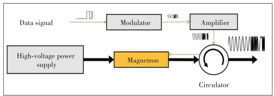
▲Figure 2. Schematic of injection-locked magnetron system
2.1 Amplitude-Shift Keying Used in Injection-Locked Magnetron
In the system shown in Fig.2,the data signal is modulated by the modulator using amplitude-shift keying (ASK).The modulated signal is amplified and injected into the magnetron through a circulator.The power of the injection signal changes from approximately 6.6 W to 22 W.The modulation depth is set to 70%.When the output power of the magnetron was measured using a signal analyzer,it was found to have shifted by approximately 6%[19].The amplitude depth of the injectionlocked magnetron output is lower than that of the injection signal.Magnetron behavior is different from amplifier behavior because the gain of the magnetron fluctuates when the injected power is increased.The modulation depth of the injected power affects the offset level of the magnetron output power.
Error vector magnitude (EVM),magnitude error (MAG Err),phase error (Phase Err),and frequency error (Freq Err) are used to evaluate the modulated signal quality.The modulated data signal uses a pseudo-noise (PN) 9 sequence.When using ASK modulation at 200 kbit/s,the quality of the injectionlocked magnetron output (Po/Pi=13.5 dB) and the injection signal are not much different as shown in Table 1.
Two conditions have to be satisfied for the injection-locked magnetron to function as an amplitude modulator.First,the modulation amplitude of the injection signal has to be lowered to keep the magnetron working in a frequency-locked state.Second,fast data rates require wide bandwidths,which have to be narrower than the locked frequency range Δf.
2.2 Phase-Shift Keying Used in Injection-Locked Magnetron
When used in the magnetron,PSK follows a procedure similar to that used by ASK.To use PSK,the modulator type in Fig.2 has to be changed from ASK to PSK.The data signal is modulated onto a carrier signal using a phase shift of 180°.The modulated signal passes through a power amplifier with an injection power of 14 W.The output of the magnetron is locked with the injection signal,and a PSK-modulated signal will be available at the magnetron output.
When the magnetron is used for PSK modulation,a double balanced mixer is used to compare a sine wave with the output signal of the magnetron.The intermediate frequency (IF) port of the mixer is connected to a low-pass filter.When the demodulated signal is observed using an oscilloscope,the rising timetriseof the phase-modulated signal at the magnetron output (Po/Pi=16.4 dB) is found to be approximately 59 ns.The maximum data transmission rate,fp,can be expressed asfp=α/trise,whereαis a constant (usually set to less than 0.35)[19].In a previous study,the response time of the magnetron was expressed as(Qe/2πf),which has been derived using Alder’s equations[18].According to this formula,a high injection power will reduce the magnetron response time,thereby enabling a high transmission rate.
We observe that the phase noise at 60 Hz caused by the filament power supply is present in the output of the injectionlocked magnetron.This phase noise can be avoided by turning off the filament power supply,high-pass filter,or phaselocked looping[17].As with ASK,the system has been designed to make the magnetron work only in the injection-locked state.With multi-value phase modulation methods,such as quadrature phase-shift keying (QPSK) and eight phase-shift keying(8PSK),the transmission rate of the data signal is found to be 10 Mbit/s when measured with a signal analyzer.The quality of the magnetron output is slightly lower than that of the injection signal,although it is still within the usable range.
2.3 Frequency-Shift Keying Used in Injection-Locked Magnetron
Frequency-shift keying (FSK) has many advantages,such as low cost and strong noise immunity.It can be used in injection-locked magnetrons.An FSK experiment is similar tothe PSK experiment.After the modulation type of the magnetron to FSK is set,the frequency deviation will also be set.The FSK-modulated signal is amplified and injected into the magnetron through a circulator,the magnetron is locked by the FSK signal,and the FSK signal is amplified.A frequency demodulator is used to demodulate the output signal of the magnetron.An oscilloscope is used to measure the relevant parameters of the demodulated signal,which are almost similar to those of the signal obtained using PSK.This injection-locked magnetron can output FSK signals at a speed of 10 Mbit/s.The relevant parameters include the carrier frequency (CF offset) and frequency deviation (Freq DEV) of the demodulated signals obtained from multi-value frequency modulated signals (Table 1).All parameters relating to FSK are consistent with those related to PSK although FSK modulation quality is better than PSK modulation quality.

▼Table 1. Parameters measured in injection-locked magnetron experiments[19]
A low modulation index will produce only a few sidebands.Multi-value FSK modulations have high bandwidth efficiency.For the same locked frequency range of Δf,a lower modulation index and multi-value FSK modulations will produce a faster transmission rate.As with ASK,the FSK bandwidth has to be narrower than the locked frequency range Δf.
2.4 Challenges Faced in Using Injection-Locked Magne⁃trons as Modulators
Compared with that of other devices,the communication bandwidth of an injection-locked magnetron is narrow because it has to be less than its locked frequency range.Because the modulation depth of an ASK-modulated signal obtained from an injection-locked magnetron cannot be linearly related to the injection signal,the use of modulation methods,such as quadrature amplitude modulation,is difficult in injectionlocked magnetrons.The maximum transmission rate of PSKand FSK-modulated signals that are currently possible is only 10 Mbit/s.It cannot be increased to 5G and Wi-Fi transmission rates without making a major structural adjustment in the magnetron.A past study has revealed that by improving impedance matching,the magnetron bandwidth could be increased[28].Utilizing a three-screw tuner,the magnetron bandwidth was increased from 2~6 MHz to 120 MHz.The bandwidth could be increased by using a time splitter or a signal separator in analog signal modulation or low-rate data communication,such as that required with motor control signals.The injection-locked magnetron for the high-power SWIPT is still the best worth looking forward to wide applications.
Regulations and standards also pose challenges.The continuous-wave magnetrons are currently being used mainly in microwave ovens and industrial heaters,which are used in closed spaces.However,because SWIPT is applied in open spaces,appropriate regulations have to be formulated.In the case of high-power SWIPT,standards specific to it have to be prepared.Magnetrons are extensively used in industrial applications using devices such as microwave ovens and other heating devices,where the low cost of the magnetrons is an advantage compared to that of other devices.
3 High-Power SWIPT Systems
The earliest use of magnetrons in communications can be traced back to the 1940s,and in 1953,the 100 W frequency variable magnetron M402,operating in the 6 GHz band with a frequency range of 1 MHz,was developed and used in a 23-channel telephone system[28].However,because of the technological limitations that existed at that time,the magnetrons used in communications were gradually replaced by klystrons and semiconductors.WEGLEIN et al.[29],TAHIR et al.[18,30],and READ et al.[31]has mentioned a magnetron being used for modulation,however,there are no actual data has been performed.Here we present the latest developments in injectionlocked magnetron systems producing modulated signals.The high-power SWIPT systems based on injection-locked magnetrons have been recently used in combination with the WPT technology to handle audio,motor control and video signals of wireless TV systems,and beamforming phased array systems used in video transmissions.
3.1 Demonstration of Phase-Controlled Magnetron Sys⁃tem Used in Radio Broadcasting

▲Figure 3. Schematic of phase-controlled magnetron system used in ra⁃dio broadcasting[19]
The noise resistance of the phase-controlled magnetron(PCM) is considered higher than that of an injection-locked magnetron.The magnetron is used to transfer an audio signal(Fig.3).The audio signal is fed into Phase Shifter 1,and the modulated signal is compared with the magnetron output by the double-balanced mixer.The signal at the IF port of the mixer representing the phase difference between the two signals compared is fed to the phase-locked loop (PLL) circuit to control Phase Shifter 2.The PLL circuit gradually reduces the phase difference between the two signals compared to bringing it to zero when the magnetron will produce a phasemodulated (PM) signal that follows the injection signal.In the receiver,the antenna is connected to a mixer,which works as a simple demodulator.The mixer produces at its IF port an audio signal corresponding to the phase difference between the signal generator output and the antenna signal.Fig.4 shows the audio signal and the signal obtained by demodulating the PM signal.In this analog phase-modulating system,the WIT system acts as a radio broadcast system.A PCM with high noise resistance will avoid the 60 Hz phase noise produced by the filament.PCMs are expected to amplify multi-value PSK signals.

▲Figure 4. Audio signal and demodulated signal obtained from a phasemodulated (PM) signal transmitted by the injection-locked magnetron(without filter)
3.2 Demonstration of a SWIPT System Used in a Remote-Controlled Electric Trolley
Fig.5 shows the schematic of the SWIPT system used in an injection-locked magnetron producing FSK-modulated signals in the microwave range.An RS-232 signal corresponding to the motor control signal is fed into a modulator that produces an FSK-modulated signal.This modulated signal is amplified and injected into a 5.8 GHz band magnetron through a circulator.The magnetron is locked with the injection signal.The magnetron outputs FSK-modulated microwaves to an electric trolley through the horn antenna shown in Figs.6 and 7.The receiver installed in the electric trolley receives the modulated microwaves and demodulates them to control the motors.Fig.8 shows the control data pertaining to the transmitted and demodulated data.The operation of the data transfer system is confirmed at a high data transmission rate,such as 115 200 bit/s.The demodulated data is fed back to the RS-232 RxD port to check the data error without bit error.
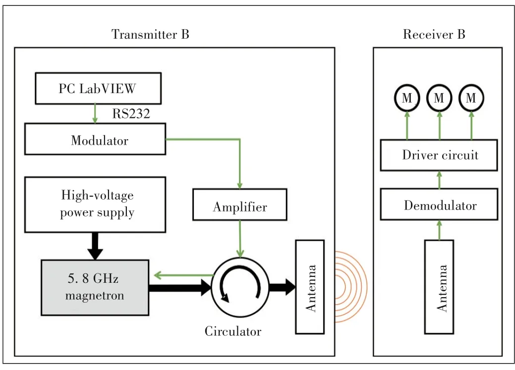
▲Figure 5. Schematic of simultaneous wireless information and power transfer (SWIPT) used in an injection-locked magnetron to control an electric trolley[32]
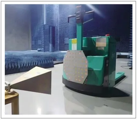
▲Figure 6. Picture of simultaneous wireless information and power transfer(SWIPT)system used in an electric trolley control system

▲Figure 7. Pictures of simultaneous wireless information and power transfer(SWIPT)system used in an electric trolley control system[32]

▲Figure 8. Modulated and demodulated signals produced by the injection-locked magnetron[32]
The experiment conducted using the 5.8 GHz injectionlocked magnetron was on the use of a 655 W SWIPT system in an electric trolley remote-control system using FSK.With their increased industrial production,electric trolleys are being widely used in work related to factory automation.The remote electric trolley control system presented in this review would be suitable for applications involving smart factory and smart warehouse logistics.
3.3 Demonstration of Use of Frequency Modulation in Television Broadcasting System
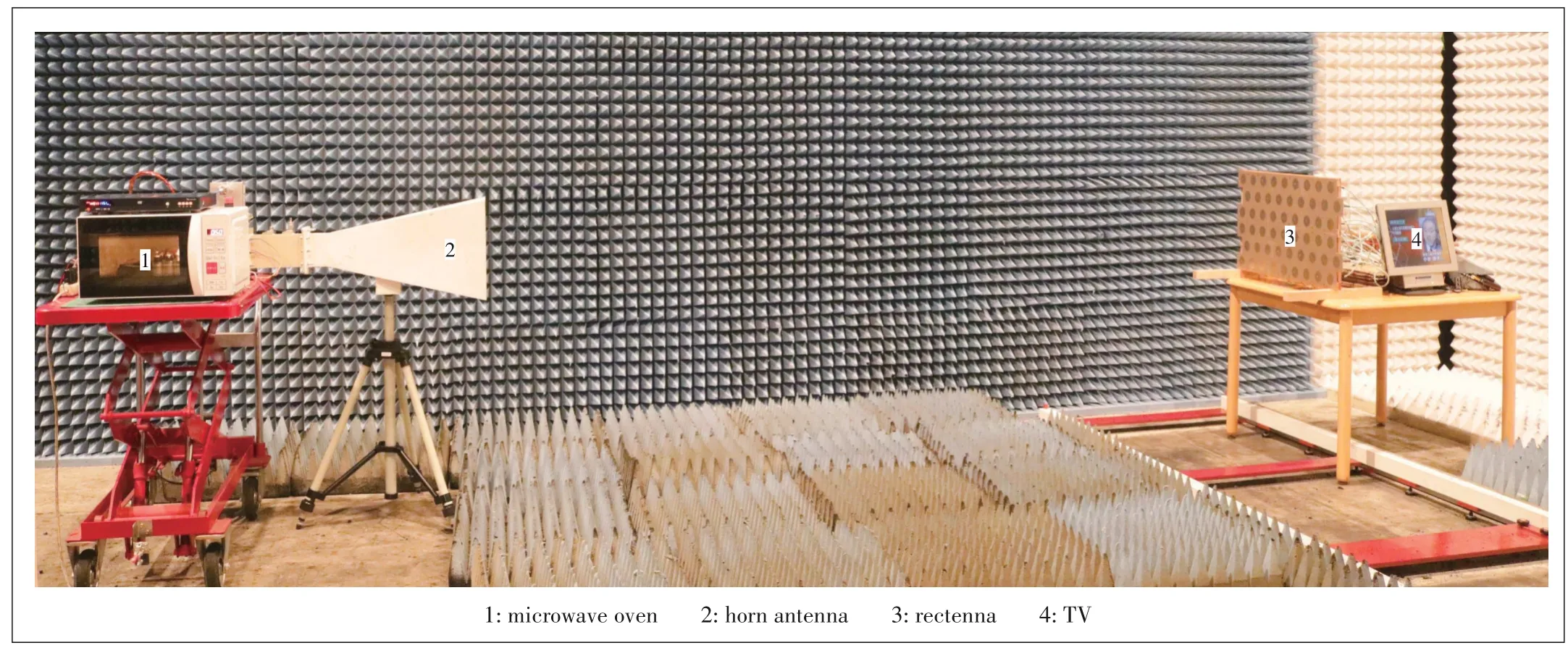
In the TV broadcasting system shown in Figs.9 and 10,FM is used with the analog video signal.A DVD player feeds audio and video signals to an FM modulator.The FM modulator output is amplified to 10 W.The modulated signal is injected into the magnetron.In the receiver,the demodulator produces the TV,video,and audio signals corresponding to the DVD signal.
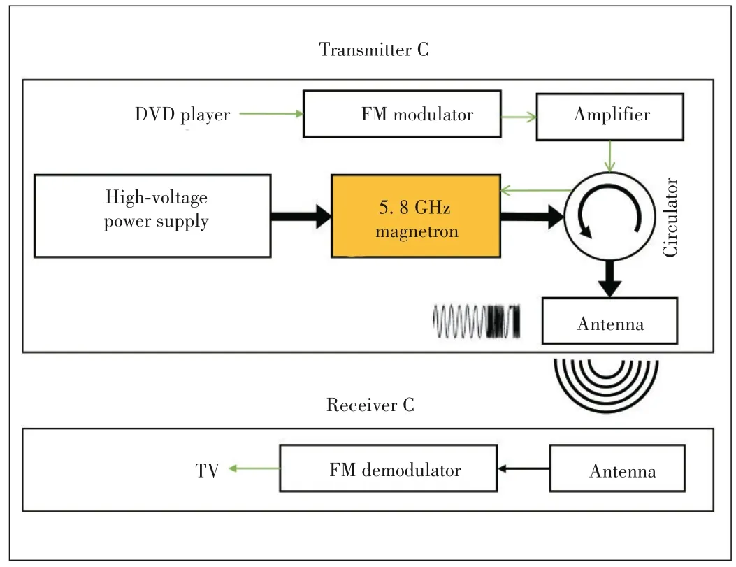
▲Figure 9. Schematic of TV broadcasting system using an injectionlocked magnetron[19]

▲Figure 10. Picture of TV broadcasting system using an injectionlocked magnetron[19]
This FM system using an injection-locked magnetron can be used in a TV broadcasting system.With digital TV becoming popular,the system may not have many applications.The system depicted in Figs.9 and 10 demonstrate that injectionlocked magnetrons can be used for low-speed audio and control signal transmissions and large-capacity data communications,such as those relating to video signals.
3.4 SWIPT System Used in Wirelessly Powered TV Broad⁃casting System

▲Figure 11. Schematic of wirelessly powered TV system[20]
Based on the FM system used in the TV broadcasting system,a microwave-driven wireless TV system using the highpower WPT technology has been developed[20].Fig.11 shows the diagram of the wirelessly powered TV system.The wirelessly powered TV,comprising a 2.45 GHz band magnetron and a power supply,was developed based on the principle used in a microwave oven.The transmitter cost was not much different from the microwave oven cost.The system demonstrates the advantages of using injection-locked magnetrons for high-power SWIPT.
The noise produced by the magnetron depends on the stability of the power supply circuit and the temperature of the electron emission filament inside the magnetron[33].The magnetron used in the system is Panasonic 2M236-M42,which has an oscillation voltage of 3.60 kV.The power supply circuit used can oscillate continuously.The power supply circuits used in microwave ovens are based on half-wave double-voltage rectifiers.The magnetron output oscillates intermittently at 60 Hz.With the intermittent oscillation of the magnetron output,the magnetron oscillation frequency changes significantly because the fluctuation of the oscillation frequency of a magnetron depends on the anode current of the magnetron.Because the magnetron has a discontinuous output with its anode current changing drastically,the oscillation frequency of the magnetron also tends to change significantly.Thus,the noise in the microwave oven would be large.The conventional PCM uses a regulated DC power supply and reduces the magnetron noise by turning off the filament.However,when the filaments in microwave ovens using half-wave double-voltage rectifiers are turned off after the magnetrons start to oscillate,the electron emissions from the filaments will stop because of the discontinuous outputs,and oscillations will not occur.The output voltage has to be maintained above the oscillation voltage to make the magnetron produce an output continuously.In the system considered,a full-wave double-voltage rectifier is used.The output of the rectifier is higher than the magnetron oscillation voltage at a 4.16%ripple rate.The oscillation bandwidth is less than 3 MHz.The injection signal has a 2 MHz bandwidth.With 10 W injection power,the magnetron can work in the injection-locked state.The DVD signal is modulated and injected into the magnetron as in the TV broadcasting system.The magnetron produces a 329 W FM microwave for transmission to the receiver.
The receiver has 54 patch antennas with each antenna connected to a rectifier.The maximum rectifier efficiency is 51.7%at a 1.8 W input power and with a 60 Ω load.One rectifier circuit is connected to the demodulator,and the video and audio signals produced by the modulator are fed into the TV.The outputs of the other rectifier circuits are connected to a DC/DC converter.The distance between the transmitter and the receiver is 3.5 m,and the receiver is fed with 48 W of DC power,which is sufficient to drive the TV.The other relevant parameters of the system are shown in Table 2 and Fig.12 shows a picture of the working wireless TV.

▼Table 2. Parameters of wirelessly powered TV[20]
▲Figure 12. Picture of wirelessly powered TV[20]
3.5 High-Power SWIPT System Used in Magnetron-Based Phased Array System
In a high-power WPT system,one magnetron is sufficient to supply the required energy.Based on the research conducted on PCM technology[17],four injection-locked magnetrons are used to construct a 2 × 2 phased array system.The output power of the magnetron phased array can be controlled from 350 W to 1 637 W.As shown in Fig.13,the phased array system transmits 1 304 W,and its receiver,which is at a 5 m distance from it,collects 142 W of DC power.The RF-RF-DC efficiency is close to 12%[25].By adjusting the phase of each PCM element,two-dimensional beamforming will be achieved.

▲Figure 13. Picture of 5.8 GHz magnetron-based phased array used in the wireless power transfer(WPT)experiment[25]
In the SWIPT system shown in Fig.14,the magnetron outputs a modulated signal.The effect of modulation on transmission efficiency is almost negligible.When measured at different modulation rates (1,10,100,and 1 000 kbit/s),the modulated beam is found to degrade the power received by less than 3%.Beamforming does not affect the modulation quality in WIT significantly.If the receiver power is sufficient for the demodulation level,communication quality will not change.The phase shifters are set for switching at 100 ms,which is close to the response time of the magnetron phased array.The magnetron phased array produces a dynamic beam at±2°.The EVMs of the dynamic and static beams are not much different.The EVMs measured in front of the magnetron phased array are similar.The EVMs are affected mainly by the received power level[34].
As shown in Figs.14 and 15,the modulated video signal is used as the injection signal.When four PCMs are injected and locked with the same modulation wave,beamforming of the magnetron phased array can be achieved by adjusting the phase of each PCM.The magnetron phased array delivers microwave beam switching to Rectennas 1 and 2 every 2 seconds.At the same time,the TV displayed a stable camera signal.Experiments conducted have revealed that video transmission could be done with dynamic beamforming[34].The results show that the phased arrays transmitting a modulated signal and those producing the beam can coexist.In this high-power SWIPT,the main lobe power is used for WPT,and the side lobe is used for WIT,which is a novel method.
4 Conclusions
This review summarizes the latest research findings on injection-locked magnetrons that can be used in high-power SWIPT.The performance of injection-locked magnetrons using amplitude,phase,and frequency modulation is evaluated.The highest data rate that could be achieved is 10 Mbit/s.These demonstration experiments of the injection-locked magnetron maintaining the high-power output have realized the modulated sound signal,motor control signal,and video signal.The wirelessly powered TV system that has been demonstrated uses a high-power SWIPT system.A high-power SWIPT used in a magnetron-based phased array,which transmits video using beam scanning,is also presented.The effects of beam scanning on signal quality and the modulated signal and on transmission efficiency are quantitatively evaluated.Technically,a practicable high-power SWIPT has been achieved.
However,in enabling the IoT and IoE society,many challenges will have to be overcome with the collaboration and cooperation of all industries.We have reviewed the latest developments of SWIPT that can be used with low-power devices and based on communication standards,such as 5G,Wi-Fi,and Bluetooth.The Japanese government is discussing WPTrelated regulations,which would set the maximum power of the system as 32 W.The devices such as drones and electric vehicles require high power for charging.Currently,no standard on high-power SWIPT used via microwaves has been formulated through consensus.Another challenge is posed by high-efficiency energy conversion technologies.The existing microwave power-amplifying devices used for communication have low conversion efficiency.Although magnetrons can perform high-efficiency conversions,their bandwidths are narrow,which does not permit high-speed communications.The traveling wave tube (TWT) has a wide bandwidth and efficient conversion capabilities.However,because of its high cost,TWT is being used mainly in satellite communications.Thus,we need to find a wide bandwidth energy conversion device that is inexpensive and highly efficient.
In the future,high-power SWIPT may be combined with 5G base stations and wireless routers.We can look forward to a future with wireless IoT and an IoE society where drones,mobile phones,and other devices operate wirelessly.
- ZTE Communications的其它文章
- Programmable Metasurface for Simultaneously Wireless Information and Power Transfer System
- A Radio⁃Frequency Loop Resonator for Short⁃Range Wireless Power Transmission
- Polarization Reconfigurable Patch Antenna for Wireless Power Transfer Related Applications
- Dynamic Power Transmission Using Common RF Feeder with Dual Supply
- Optimal Design of Wireless Power Transmission Systems Using Antenna Arrays
- Editorial:Special Topic on Simultaneous Wireless Information and Power Transfer:Technology and Practice

