Design of monitoring system for temperature and humidity of garlic cold storage based on the Internet of Things technology
Wang Chen, Ma Ye, Li Wei, Zhang Jie, Praveen Kumar Donta, Chen Guangming, Xiao Maohua*
(1.College of Engineering, Nanjing Agricultural University, Nanjing 210031, China;2.Xuzhou Aidi Food Co., Ltd., Xuzhou 221124, China;3.Jiangsu Agricultural Machinery Test and Appraisal Station, Nanjing 210017,China;4. Vienna University of Technology, Vienna 999013, Austria)
Abstract: With the continuous development of Internet of Things technology, various work scenarios have higher requirements for real-time communication between devices.This paper designs a temperature and humidity monitoring system for garlic cold storage, using ZigBee wireless communication technology and the function of serial port transfering to wireless of ESP8266 to realize the real-time collection of temperature and humidity data of garlic during storage.Through the interconnection of Aliyun database RDS with PC and mobile applications, the record of temperature and humidity information in the whole cycle of garlic cold storage is completed, and the function of real-time notification of cold storage alarm information without time and location restrictions is realized.The field experiment is designed and implemented based on the system , and the experimental results show that the operating performance of the system is stable.
Keywords: Garlic refrigeration; Data interconnection; ZigBee technology; CC2530; ESP8266
0 Introduction
Garlic is one of the main varieties of agricultural products exported in my country, with an annual export of about 300 000 t.Among them, refrigerated garlic accounts for about 60% of the total export volume.Therefore, garlic has great demand for cold storage and cold chain logistics, but there is relatively few research on garlic cold storage in China.The development of garlic cold chain industry is not mature enough, and many monitoring and preservation technologies are not fully integrated, which restricts the commercialization and industrial application of fresh garlic.In the traditional facility agricultural management process, the detection and control of environmental parameters are mostly managed by manual or wired wiring, which has problems such as untimely monitoring, complicated wiring, high cost, and inconvenient maintenance[1-2].
In recent years, many researchers have also done a lot of research on Internet of Things facility agriculture.Shi[3]designed a grain situation management system, based on Cortex-M3 microcontroller, using sensors to collect information in the warehouse, including grain reserves measurement, temperature measurement, humidity measurement, and other functions.He chose ZigBee as data transmission, established a communication network and developed the field computer according to the remote management website deployment; Ren[4]proposed a warehouse environment monitoring system based on the Internet of Things.A wireless sensor network with multiple nodes is deployed in the warehouse.The device wirelessly transmits the collected data to the microprocessor, which compares the collected data with the set threshold and controls the peripheral equipment to adjust the environmental parameters of the warehouse to ensure the quality of the goods and reduce the potential safety hazard of storage; Liu[5]have also designed an intelligent greenhouse monitoring system based on the wireless network, which innovatively adopts the combination of mobile collection and fixed-point collection and can collect greenhouse environmental data and upload it to the client developed by LABVIEW.These projects well implemented the environmental parameter collection and monitoring function, reduced the human cost and proved the huge productivity of Internet of Things technology in facility agriculture.However, the flexibility and real-time performance of the system in facility agricultural monitoring and management are still not high, and the convenience of data and information access can also be optimized.
Based on the experience of predecessors, this paper designs a ZigBee-based temperature and humidity monitoring system for garlic cold storage, which can realize the temperature and humidity information in the cold storage to be viewed by the computer terminal and mobile client anytime, anywhere, and alarm in real time, so that the cold storage manager can manage it in time.The system obtains the real-time data of temperature and humidity in the garlic cold storage through the temperature and humidity sensor in the cold storage and sends it to the coordinator through the ZigBee wireless network.The coordinator gateway transmits the data to the cloud platform database with the help of the ESP8266 module.The cloud platform analyzes, processes, displays and archives the data, completes the environmental information recording of the whole storage cycle of garlic and sends it to the computer and mobile clients.The system has the advantages of low power consumption, low investment cost, simple wiring, strong stability, high real-time performance and the ability to provide alarm information from a long distance, which greatly improves the management efficiency of garlic cold storage.
1 System design
The ZigBee-based garlic cold storage temperature and humidity monitoring system can collect the temperature and humidity data in the cold storage in a timely and accurate manner, transmit the data to the cloud platform, and then compare with the set upper and lower index values.If the data exceeds the index value, the system will alarm the management personnel through the client until the temperature and humidity return to the set range[6].In order to meet the functional requirements, the system has three parts as detection and perception part, wireless gateway part, and data processing part.The system structure is shown in Figure 1.In the process of network establishment, the coordinator starts and follows the ZigBee protocol, conducts a series of sessions between layers, completes the configuration of various parameters of the network until the network is successfully established, and then the routing nodes gradually join the newly established network.According to the protocol, each layer of the router and the coordinator completes the configuration of their own parameters after establishing multiple sessions respectively, after which each node in the network can communicate with each other[7].The detection and perception part contains a terminal node composed of multiple temperature and humidity sensors and communication modules.The terminal node finds and connects to the router.After the sensor detects the temperature and humidity data, it transmits the data to the router.The router can transmit data packets between each terminal node, and allow child nodes to join.The wireless gateway part is the core part of the wireless communication of the system, which is mainly composed of the coordinator and the ESP8266 module.The coordinator selects the initial communication channel, initializes the network configuration and accepts child nodes to join the network.The ESP8266 module converts the transmission protocol, establishes a connection with the Internet and transmits the temperature and humidity data to the cloud platform.The main working process of the data processing part is that the cloud platform processes and records the temperature and humidity information, and displays the current cold storage environment status on the client side in real time.If the temperature and humidity information is not within the range of the index value, the client interface will send an alarm message in time.
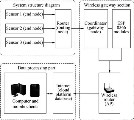
Figure 1 System structure diagram
1.1 Hardware design
The detection and perception part mainly realizes the functions of temperature and humidity data collection, preliminary processing and forwarding.It consists of a sensor module and a data processing module and is a key part to obtain the environmental information of the cold storage.Considering its power consumption and practicability comprehensively, low power consumption and stable communication functions are the primary considerations to achieve all-weather work and analog and digital data processing and forwarding[8].After selection, this design uses the CC2530 module as the control chip.The CC2530 module is a single-chip solution specially designed for IEEE 802.15.4 and ZigBee applications.It integrates a fully integrated high-efficiency RF transceiver and an industry-standard enhanced 8051 microcontroller.It has 8 KB RAM, two USARTs, 12-bit ADC and 21 general-purpose GPIOs, which can build powerful wireless sensor networks with very low power consumption and low cost[9-10].The temperature and humidity sensor module selects SHT30 for sensor.Compared with the previous generation, the SHT30 sensor further enhances the reliability and accuracy specifications of the product, strengthens the signal processing capability, and increases the communication speed to nearly 1 MHz.The humidity measurement range of the sensor is 0-100%RH, and the temperature measurement range is-40 ℃-125 ℃, which meets the needs of this system.The work flow is shown in Figure 2.The power supply circuit is responsible for supplying power to the temperature and humidity sensor and the CC2530 module.The circuit can be powered by an external power supply and a dry battery.The digital core and peripherals of the CC2530 are powered by a low-dropout regulator, which provides power management features that enable low-power operation with long battery life using different power modes.The system uses a dry battery to supply power.The CC2530 chip uses two crystal oscillator circuits to provide the clock signal, and it is connected with the temperature and humidity sensor through the interface circuit to obtain the detected temperature and humidity data.The wireless sensor network is constructed by connecting the antenna with the radio frequency circuit, and the temperature and humidity data are sent to the router or the coordinator gateway[11].

Figure 2 Workflow of detection perception
The wireless gateway part is the core part of the system, mainly composed of the coordinator part and the ESP8266 module, which can realize the functions of receiving temperature and humidity data, accessing the Internet and uploading the data to the cloud platform.The structure is shown in Figure 3.In order to simplify resources, the ZigBee network topology selected by this system is a cluster network, which can be regarded as an extended star topology[12].The functions of the network coordinator, router and terminal equipment are clear.The temperature and humidity data detected by the sensor terminal is transferred through the router in the wireless network established by CC2530 according to the Z-Stack protocol, and received by the radio frequency transceiver in the coordinator and stored in Flash[13].Because the Z-Stack protocol and the TCP/IP protocol are not interoperable, this system selects the ESP8266 module for protocol conversion.Set the ESP8266 module to Station mode through the AT command set that comes with ESP8266, and then connect to the network of the hotspot AP in the cold storage, establish a TCP connection, and connect the coordinator to the Internet.
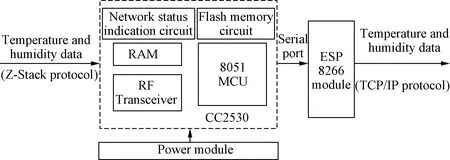
Figure 3 Structure diagram of the wireless gateway part
1.2 Software design
Before communication, a complete ZigBee network needs to be formed, and the system network is established by the network layer of the ZigBee protocol stack.The wireless network program is made with the protocol stack Z-Stack-251a developed by TI, using the development environment which is IAR Embedded Workbench for 8051 8.10.1 and the programming language which is C language.
The process of building the network mainly consists of two steps.The coordinator is responsible for the establishment of the network, the parameter configuration, and the router and the terminal nodes finding and joining the network, and its software process is shown in Figure 4.After the coordinator receives the call to the new network, it will scan on the specified channel.After determining no parameter conflict, the coordinator obtains the network identification PANID, the ZigBee network layer will select 0x0000 as the 16-bit network address notify the MAC layer to set it to the network address, and then only the network of the coordinator node on the appropriate channel is established[14].Next, the router or terminal node will first scan the surrounding channels to obtain the address information of the network coordinator or router with the ability to allow connection within its POS range[15].In this system, the network topology is a cluster network, for the router, the coordinator is its parent node, itself a child node, and for the terminal node, the router is its parent node and itself a child node.The child node first sends the beacon request command to the surrounding parent node, and the first parent node that receives the command sends its beacon frame to the child node.After obtaining the parent node information to be added, the child node will send the connection request command to it, and the parent node will check the current resource status[16].If the resource situation is met, the parent node will store its address and assign it a 16-bit network address, generate the connection response command frame, and send the ACK response frame with untreated data to the child node.After receiving the ACK response frame, the child node will send the data request command to the parent node, the parent node will send the connection response command frame, and the child node will update its device network address, PANID, the parent node device address information, and other parameters.At this time, the process of adding PAN is completed[17].The configuration process is shown in Figure 5.
Data transmission is divided into two stages.The first stage is the transmission between following the Z-Stack protocol in the terminal nodes and the coordinator, and the second stage is between the coordinator and the cloud platform, which is based on the TCP/IP protocol.The first stage is relatively simple.The data is encapsulated as a MAC data frame in the child node MAC layer, which is transferred to the node network layer and received by the parent node network layer[18].
Then, the parent node commands and answers the data.The source address of the data frame is the network address of the child node, and the destination address is the address information of the next parent node calculated by the corresponding routing algorithm.After being transmitted, forwarded, and received by each node, the data finally reaches the coordinator to save and start the transmission of the second stage.Since the Z-Stack protocol does not communicate with TCP/IP protocol, which affects the process of uploading data to the cloud, the system adopts the ESP8266 module for protocol conversion.ESP8266 module is connected to CC2530 through the serial port and CC2530 transmits data to ESP8266 every 5 minutes through timing program.ESP8266 module uploads data to cloud platform database in Station working mode, and working mode configuration is completed by AT instruction.The configuration process is shown in Figure 6.
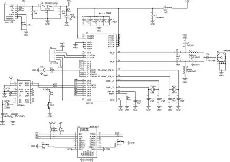
Figure 4 Electronic circuit diagram of the wireless gateway part
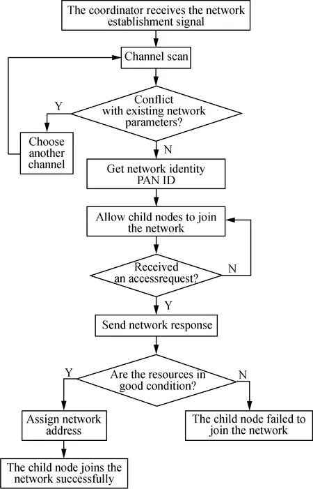
Figure 5 Software flow chart
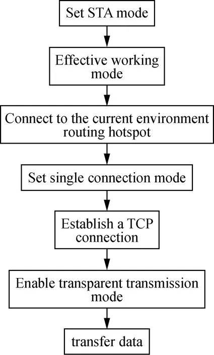
Figure 6 ESP8266 working mode configuration process
At the system function software implementation level, the first thing to solve is the development and establishment of the database.Self-built servers are often complicated, with large input costs, and limited to Intranet use, which limits the function realization of the monitoring system.Therefore, this system adopts the cloud database RDS, which is an online relational database service, running in the cloud, based on Aliyun Feitian distributed operating system and full SSD disk high-performance storage[19].Compared with self-built servers, cloud database RDS can greatly reduce the work of developers and supports different database engines such as MySQL, Oracle, SQL Server, and PPAS, which can purchase the corresponding services according to their own needs and have the right to use a database.To realize the collection, storage, and analysis of temperature and humidity information of garlic cold storage, a new database is built on the Aliyun database page and a new cold storage data table is selected, including the following fields: ID, Node, House, Time, Temperature, Humidity, which are respectively used to record the sensor address, node number, location, record time and temperature and humidity information[20].
The client has two ways: PC and mobile.Both are developed by HTML5 with highly visual interactive interfaces.The difference is that mobile applications need to package HTML files into Android and Apple installation packages using the API and components of the API Cloud platform.The backend of the client is developed based on PHP, which can obtain database information through the interface and have good support for the database.The PC interactive interface is shown in Figure 7, which can display the real-time temperature and humidity of the node environment, display the temperature and humidity change curve within 24 hours, and obtain the data uploaded by the terminal node every 5 mins from 0 PM on the same day through the "Detailed Data" button.The mobile terminal interface is shown in Figure 8, and the function is consistent with the PC terminal.The client can compare the real-time temperature and humidity data with a reasonable range.If the real-time data overflows the reasonable range, the client will immediately respond and notify the management personnel to check[21].
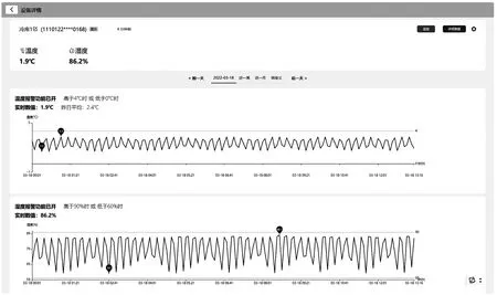
Figure 7 PC terminal interface
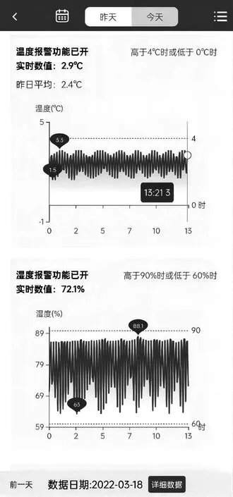
Figure 8 Mobile terminal interface
When the system alarms, the mobile client interface responds as shown in Figure 9.The client sends the alarm information to the user, displays a reminder that the temperature and humidity are too high in the interface, which can be clearly observed in the graph interface that the temperature and humidity exceed reasonable range boundaries, and display real-time data.

(a)Alarm interface
(a)Response time curve
2 Experiment and analysis
The general design of the ZigBee-based temperature and humidity monitoring system for garlic cold storage has been completed before.To verify the real-time of the system and the ability to provide alarm information at a long distance, the following experiments are carried out.
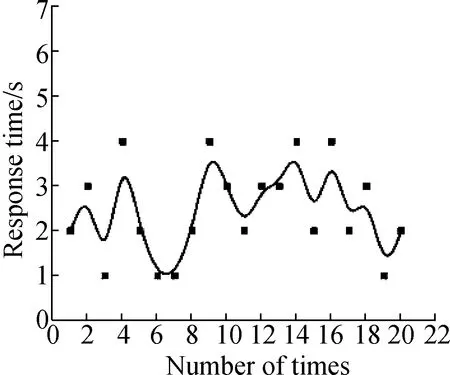
The experiment is conducted in the garlic storage warehouse of a food company in Jiangsu province, which is composed of five identical cold storage warehouses connected side by side.Each cold storage covers an area of about 300 m2and has a height of about 7 m.The shelf height for garlic in cold storage is 1.65 m.In each cold storage, four temperature and humidity sensors are evenly arranged and each one is equipped with a CC2530 module.A ZigBee network router is configured in each cold storage, and the coordinator is set in the management room next to the cold storage, connected with the ESP8266 module, which is configured with STA working mode and connected to WIFI hot spots.First, a tester waits for the client to respond at a location 10 km away from the company with a good network environment, and set a reasonable range of temperature and humidity in the mobile client: temperature from 0 ℃ to 4 ℃, and humidity from 60% to 95%.Then another tester enters the cold storage and randomly selects a sensor node, uses a heating and humidifying device to increase the temperature and humidity of the surrounding air, and records the timet1when the temperature and humidity just exceed the interval.The first tester observes the response of the client, and records the timet2and the temperature and humidity data at the alarm time.The response time is calculated by subtracting the two times, and the alarm accuracy is tested by the temperature and humidity exceeding the interval data at the alarm time.Multiple tests are performed using the above method.
The experimental results are shown in Figure 10 calculated by numerical fitting.The comprehensive response time is 2.26 s, temperature alarm accuracy is 0.16 ℃, and humidity alarm accuracy is 1.4%.In the long-distance test, the response time is very short, which proves the high real-time performance of the system.At the same time, the test shows that the system can achieve good alarm accuracy, which can meet the needs of daily production and life.
3 Conclusions
The temperature and humidity monitoring system for garlic cold storage based on the Internet of Things technology designed in this paper uses ZigBee wireless communication technology and the serial port to wireless function of ESP8266 to realize the real-time collection of temperature and humidity data in the process of garlic storage and record the full-cycle temperature and humidity data in the cloud.At the same time, with the cloud database connected to the client, managers can obtain data anytime and anywhere, and carry out early warning processing in a timely manner.This system provides a way of thinking for the management of cold storage facilities, but only realizes the basic information collection function.In practical applications, two-way tasks such as the ability to adjust and control the environment through the host should also be considered[22].Therefore, establishing an IoT monitoring and control system with a higher degree of integration and automation is an important direction for further improvement of the system.
- 智能化农业装备学报(中英文)的其它文章
- 4CJ-1200F智能采茶机设计与试验
- Research progress on key technologies of agricultural machinery unmanned driving system
- Structure design and experiment of air suction double-layer cylinder seedling raising and sowing line
- 自走式蔬菜精量播种施肥系统设计与试验
- Effects of straw return years on organic carbon and total nitrogen distribution in soil aggregates from rice-wheat rotation fields
- Analysis of application status of intelligent manufacturing in agricultural machinery

