Design and development of a five-axis machine tool with high accuracy, stiffness and efficiency for aero-engine casing manufacturing
Yutian WANG, Dong WANG,*, Shizhen ZHANG, Zihan TANG,Liping WANG, Yanmin LIU
a State Key Laboratory of Tribology and Institute of Manufacturing Engineering, Department of Mechanical Engineering,Tsinghua University, Beijing 100084, China
b Beijing Key Lab of Precision/Ultraprecision Manufacturing Equipment and Control, Beijing 100084, China
c Beijing Precision Machinery & Engineering Research Co. LTD, Beijing 101312, China
d Beijing Institute of Control Engineering, Beijing 100094, China
KEYWORDS Aero-engine casing manufacturing;Compact motorized spindle;Dual drive swing head;Five-axis machine tool;Supporting stiffness
Abstract In order to satisfy the machining requirements of aero-engine casing in modern aviation industry, this paper investigates three main issues during the design and development process of a five-axis machine tool with high accuracy,stiffness and efficiency,including whole structure design,key components design,and supporting stiffness design.First,an appropriate structure of five-axis machine tool is determined considering the processing characteristics of aero-engine casing.Then,a dual drive swing head and a compact motorized spindle are designed with enough drive capability and stiffness, and related structure, assembly method, cooling technology, and performance simulation are given in detail.Next,a design method of supporting stiffness of guide is proposed through the deformation prediction of the spindle end.Based on above work,a prototype of machine tool is developed, and some experiments are carried out, including performance tests of swing head and motorized spindle,and machining of a simulated workpiece of aero-engine casing.All experimental results show that the machine tool has satisfactory accuracy, stiffness and efficiency, which meets the machining requirements of aero-engine casing. The main work can be used as references for engineers and technicians, which are meaningful in practice.
1. Introduction
Machine tool is regarded as one of the most important equipment in industry(known as‘‘mother machine”),and five-axis machine tool is generally used to complete the machining of complex parts,which plays a very important role in many key areas, such as aviation, aerospace, automobile, shipping,and energy. With the rapid development of manufacturing industry,a large number of new processing technologies,materials, and structures have been gradually used, which leads to the quickly increased demand of five-axis machine tool with high performance. Meanwhile, as the basic unit of smart factory, the actual performance of machine tool directly affects the property of the whole manufacturing system. Thus, it is significant to carry out investigations of machine tool.
Higher accuracy and efficiency have always been the development goals in machine tool filed, and researchers have performed some related effective studies. For example, geometric error modeling, identification and compensation,thermal error prediction and compensation,chatter detection and suppression,tool wear monitoring and prediction,spindle accuracy measuring,contouring and tracking control,control of hybrid/parallel machine tools,application of direct-drive (DD) technology,tool path planning for complex part,and interface damage in machining process.Among all studies, design and development of a machine toolcan be considered as the essential issue,which provides a platform for other following researches,such as calibration, control, detection, and processing technology.Design and development of a machine tool is not easy, especially a five-axis machine tool with satisfactory performance,which is a systematic process requiring a long period, a lot of practice and multi-domain knowledge.
Structure determination is the first mission during the design and development process of a five-axis machine tool,which needs to not only meet the processing requirements but also bring better initial performance. Next, key components and parameters need to be considered, such as swing head, spindle, and supporting stiffness. Finally, a comprehensive test should be carried out for key components and whole machine. However, due to the commercial competition, most high-grade five-axis machine tools only give nominal technical parameters, such as the accuracy of motion axis and the rotation velocity of spindle,and the design details are generally not public, including the specific structure, the assembly method,and the actual experimental data.Thus,there is a lack of effective references for engineers and technicians when designing high-grade five-axis machine tools.
Aiming to meet the machining requirements of aero-engine casing in modern aviation industry, this paper designs and develops a five-axis machine tool with high accuracy, stiffness and efficiency,and three main issues are investigated,including whole structure design, key components design, and supporting stiffness design. An appropriate structure of the machine tool is firstly determined by analyzing the processing characteristics of aero-engine casing. Then, the design details of a dual drive swing head and a compact motorized spindle are described, respectively. Next, the supporting stiffness design of guide is completed through the deformation prediction of spindle end. Finally, a series of experiments is carried out to validate the performance of the five-axis machine tool. It is expected that above work could provide references for engineers and technicians in practice.
The rest parts of the paper are organized as follows: Section 2 determines the whole structure of the machine tool;Section 3 presents the design details of the swing head and the motorized spindle;Section 4 completes the supporting stiffness design of the guide; Section 5 performs the experiments; Section 6 states the conclusion.
2. Whole structure design of the machine tool
Casing is a core component of aero-engine,its machining quality greatly affects the performance, fuel consumption and service life of aero-engine. A typical aero-engine casing is a large rotation part with thin-wall, as shown in Fig. 1. The diameter and the wall thickness of aero-engine casing are generally from 600 to 800 mm and 1.5 to 3 mm, respectively, meanwhile, the material of aero-engine casing is hard to process,such as stainless steel and titanium alloy. The boss (or island) distributed along the circumferential direction is the main shape feature of aero-engine casing, which requires high accuracy.Because of the angle between the boss plane and the reference plane,the aero-engine casing manufacturing is not easy,which needs five-axis machining equipment to complete. Moreover,due to the high productivity requirement of modern aviation industry, it is necessary to improve the machining efficiency while ensuring high accuracy. In order to satisfy the manufacturing requirements of aero-engine casing, it needs to design and develop a five-axis machine tool with high accuracy, stiffness and efficiency.
Besides the conventional translational axes, it is necessary to make the machine tool have two rotation axes to complete the machining of aero-engine casing. There are two combinations of rotation axes for five-axis machine tool, i.e. RR-type and RR-type. RR-type represents the integrated swing head or work table with two rotation axes, as shown in Fig. 2.For the integrated swing head, the processing routes of translational axes are long when machining the distributed boss,which decreases efficiency. For the integrated work table, the rotation range of A-axis is limited considering structural interference, and the performance of A-axis is heavily affected by the variable gravitational moment of aero-engine casing.
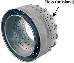
Fig. 1 A typical aero-engine casing.
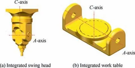
Fig. 2 RR-type.
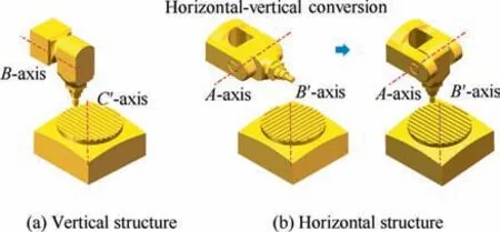
Fig. 3 RR′-type.
Compared with RR-type, RR-type means that the swing head and the rotation table are separated, as shown in Fig. 3, in which the work table can achieve the rotation of 360 degrees to realize the quick positioning of boss during machining process. In addition, the performance of rotation table is easy to guarantee because the gravitational moment of aero-engine casing is almost unchanged. The difference between Fig. 3 (a) and (b) is the swing head, i.e. the vertical structure and the horizontal structure. The horizontal structure can ensure that the cutting tool axis is perpendicular to the platform of boss, which is more convenient than vertical structure when machining hole and keyway of casing. In fact,by designing enough swing range of the swing head (i.e.≥90), the horizontal structure can be converted to vertical structure, which is also shown in Fig. 3 (b).
Based on above analyses,Fig.3(b)is the most appropriate structure, and by adopting this structure, a five-axis machine tool is designed for aero-engine casing manufacturing, as shown in Fig. 4. The five motion axes are defined as X, Y,Z, A, B, and the main advantages of the machine tool can be described as follows:
1) High stiffness: the structural dimensional chain is relatively short because the two rotation axes are separated,which is beneficial to improve the stiffness;
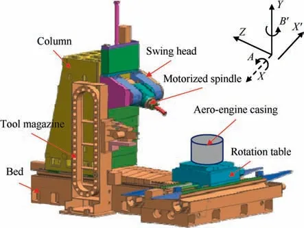
Fig. 4 Whole structure of machine tool.
2) High accuracy: the machining accuracy of aero-engine casing is separately controlled by the swing head and the rotation table,which could reduce the error accumulation and coupling;
3) High efficiency: there is no dead point in the full stroke of swing head, and the positioning of each boss can be quickly completed by the rotation table, which brings very high machining efficiency.
Furthermore, based on the detailed requirements from some aero-engine manufacturing companies, the basic technical parameters of the five-axis machine tool are determined,as shown in Table 1.
The swing head, the spindle, the rotation table, and the translational axes (i.e. ball screw drive systems) are the core components of the machine tool.It should be pointed out that the rotation table and ball screw drive systems are relatively mature than other parts, and there are some products can be directly chosen, thus, the swing head and the spindle are the main focuses in this study.
3. Swing head and motorized spindle
Because the material of aero-engine casing is hard to process,the swing head and spindle must have strong drive capability and high stiffness. Moreover, the direct-drive technology should be used to reach high speeds of swing head (i.e. 60(°)/s)and spindle(i.e.8000 r/min).In this section,a dual drive swing head and a compact motorized spindle are designed to meet these requirements.
3.1. The dual drive swing head
The whole structure of the swing head is shown in Fig. 5,which consists of two torque motors, a radial grating, two roller bearings, two pneumatic braking clamps, and a cross shaft. Compared with traditional swing head with one drive motor, this structure is strictly symmetrical about the central plane of spindle, which brings two main advantages, as:
1) The symmetrical structure with double torque motors meets the requirement of large drive capability when machining hard-to-cut materials, also realizes the symmetry of thermal load;
2) The supporting and clamping forces are all symmetrical about the central plane of spindle, which improves the supporting stiffness of spindle and also reduces the effects on accuracy caused by unbalanced forces.
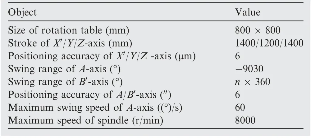
Table 1 Basic technical parameters of five-axis machine tool.
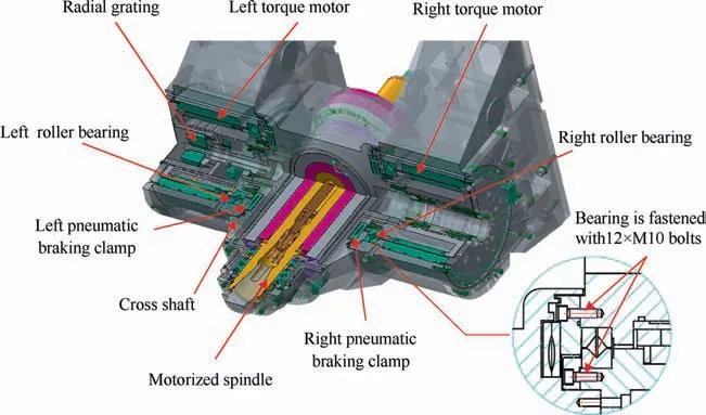
Fig. 5 Whole structure of dual drive swing head.
The left torque motor is set as the master one, which receives the position instruction, meanwhile, the right torque motor is set as the slave one,which receives the torque instruction.In addition,only one radial grating is used to measure the velocity and position of A-axis,thus,the concentricity between the left and right motors should be ensured well to guarantee the synchronous property.
The pneumatic braking technology is used due to its simple structure with easy control, instead of traditional hydraulic braking. The maximum clamping torque could achieve more than 2600 N·m when the air pressure is 0.6 MPa, and the safety could be ensured well during the machining process.Moreover, because of the symmetrical arrangement of the two pneumatic braking clamps, the effect on the accuracy of spindle is very small.
The rotor of torque motor is permanent magnet, and the magnetic force is about 20 N/cm, which brings great difficulties to the motor assembly. In order to improve the assembly accuracy, a special non-magnetic fixture is developed, as shown in Fig. 6, which is composed of base, upper/lower connector, positioning shaft, guide rod, fastening screw, and adjusting screw. During the assembly process, the rotor is firstly placed on the positioning shaft, then, its positioning can be precisely realized through the guide rod and the adjusting screw,finally,the fastening screw is used to fix its position.
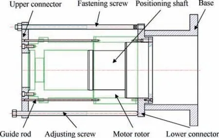
Fig. 6 Special non-magnetic fixture.
3.2. The compact motorized spindle
The drive motor of traditional motorized spindle is rear-placed to reduce the hearting effect, but this spindle has long structural chain, which decreases the stiffness and flexibility, and is not suitable for machining aero-engine casing.In this study,a compact motorized spindle is designed with built-in motor structure to improve the stiffness and flexibility, which is shown in Fig. 7. This compact structure has a small number of parts, and it is easy to achieve high speed. The front bearings are three columns of angular contact ball bearings with positional preload mode, and the arrangement form is back to back.Meanwhile,the rear bearing is single column of cylindrical roller bearing, which only suffers radial load. This arrangement of bearings is easy to assemble while ensuring the stiffness, and the thermal deformation is backward extended. In this study, the contact angle and the rolling element of the front bearing are 18° and Si3N4 ceramic ball,and the nominal radial stiffness and the nominal axial stiffness are 770 N/μm and 150 N/μm, respectively. In addition, the nominal radial stiffness of rear bearing is 400 N/μm.
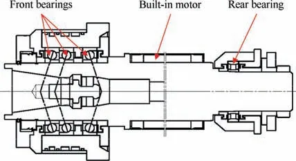
Fig. 7 Structure of compact motorized spindle.
On the other hand, because of the compact structure characteristic, the accuracy of the spindle will be affected by the heating parts, thus, related cooling technology must be used to quickly realize a thermal steady state. Besides traditional cutting fluid cooling and natural cooling, a liquid cooling system is established for this compact motorized spindle, as shown in Fig. 8, in which there are two mutually independent cooling channels for the two main hearting parts,i.e.the builtin motor and the bearings.The cooling entrance and export of motor are located in the front end and rear end of the spindle,respectively, and most heat generated by motor can be taken away when the cooling medium flows past the stator groove.Similarly, the heat generated by bearings can also be taken away through the cooling channel.
After designing,simulation is very important to validate the performance of the compact motorized spindle in theory.Based on the finite element method (FEM), the static and dynamic performances of the spindle are further analyzed,including radial stiffness and natural frequency.
Because the spindle has symmetrical structure, the section element is used to complete the mesh dividing, instead of volume element, as shown in Fig. 9 (a), which is beneficial to reduce computation time. In this study, there are totally 154 nodes, and the smallest element length is 10 mm. Considering that the assembly mode is interference or fastening,some parts of the spindle are regarded as the added mass during the calculation process,including the inner ring of bearing,tool tensioning device, sensor sleeve, and motor rotor. The constraint model is shown in Fig. 9 (b), in which the front end and rear end are set as the fixed and removable supports, respectively.The constraints between bearings (i.e. nodes 51, 59, 62, and 16) and seats (i.e. nodes 142, 145, 147, and 99), tool holder(i.e.nodes 75 and 82)and shaft(i.e.nodes 60 and 67),bearing seats(i.e.nodes 139 and 100)and fixed surface(i.e.node 0)are all equivalent to spring-damper. Based on the contact modes and basic calculation examples, the detailed parameters of these constraints are given in Table 2.
During the calculation process, the load Fis given at the node 88, as F=1793 N, and the deformation δis 5.863 μm,thus,the radial stiffness of the spindle is obtained as:

where Kis the radial stiffness of the spindle, and the simulation result indicates that the compact spindle has enough stiffness, which is more than 300 N/μm.
Furthermore, the first order natural frequency of the compact motorized spindle is also calculated through FEM, and the result is shown in Fig.10.The maximum speed of the spindle is 8000 r/min, which means that the working frequency is less than 133.3 Hz.Based on Fig.10,the first order natural frequency is 350.3 Hz, which is much larger than the highest working frequency. Thus, the compact motorized spindle has strong anti-vibration ability in theory.
It should be pointed out that only the simulations of motorized spindle are given in this Section.The reasons can be summarized as follows: 1) During the machining process, the spindle is directly contacted with workpiece through tool and tool holder, thus, the static and dynamic performances of the motorized spindle are very important, which need to be verified through FEM;2)The main requirement of the swing head is the drive capability, and in order to ensure that the swing head has enough drive capability, the dual drive form is adopted with two torque motors. Thus, the simulations by using FEM are selectively performed for the motorized spindle to save time cost.
4. Supporting stiffness design of guide
After designing the dual drive swing head and the compact motorized spindle,the main geometrical parameters and gravity load of each axis can be determined combining the requirements of workspace with the existing parts, such as ball screw and guide.During this process,how to design appropriate supporting stiffness of guide is a core step, which determines whether the machine tool has enough stiffness.In this section,a design method of supporting stiffness of guide is proposed based on the deformation prediction of the spindle end.
The supporting diagram of Z direction is shown in Fig.11,where A represents the front endpoint of spindle; F, Fand Fare the external loads along X ,Y and Z directions, respectively; Cand Ware the center and gravity of swing head,respectively; Cand Ware the center and gravity of column,respectively. The situation when the swing head in the highest position is considered to calculate the maximum deformation of the spindle end.Considering the large load of Z-axis,6 sliders are used, and Fand Fare the normal load and lateral load of the ith slider,respectively.Moreover,M,Mand Mrepresent the torque loads of the sliders.
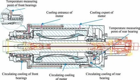
Fig. 8 Liquid cooling system of compact motorized spindle.
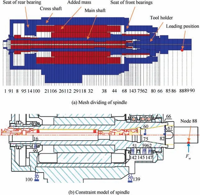
Fig. 9 Performance simulation of compact motorized spindle.

Table 2 The detailed parameters of constraints.
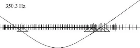
Fig. 10 First order natural frequency and mode of spindle.
As mentioned before, the materiel of aero-engine casing is hard to process, and in order to ensure that the machine tool has enough supporting stiffness, the external loads are set as:

whereF,Fand Fare determined by appropriately enlarging the cutting force and drilling force when machining stainless steel.
Based on Fig. 11, the torque loads can be obtained as:

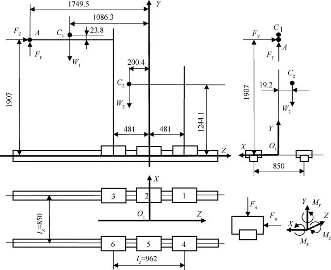
Fig. 11 Supporting diagram of Z direction.
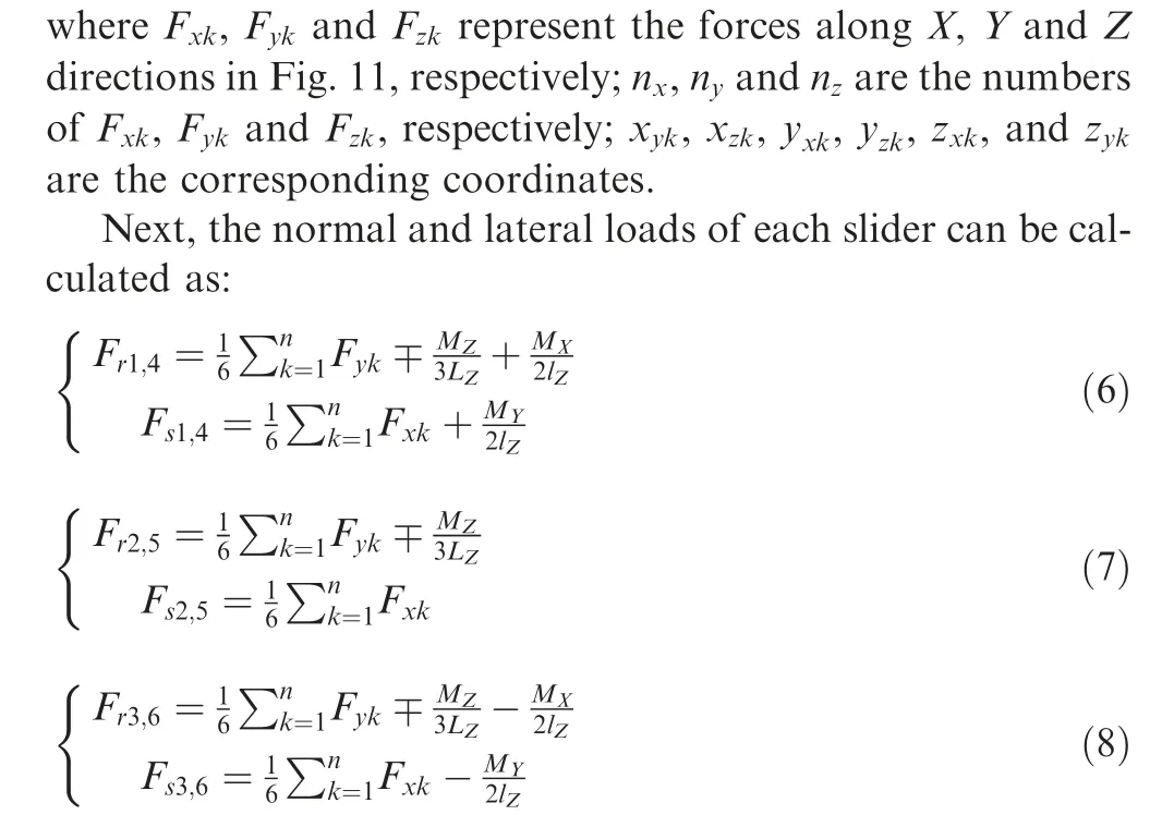
where Lis the span of guide, lis the distance between sliders.
Assuming Kand Kare the normal stiffness and the lateral stiffness of Z direction guide,the deformation of the spindle end can be predicted as:
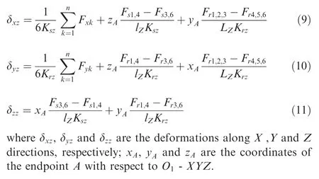
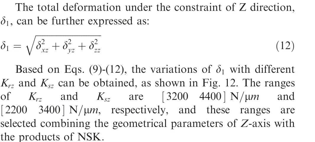
Similarly, the supporting diagram of Y direction is shown in Fig. 13, and because the load of Y-axis is relatively small,4 sliders are used. The total deformation under the constraint of Y direction, δ, can be calculated as:
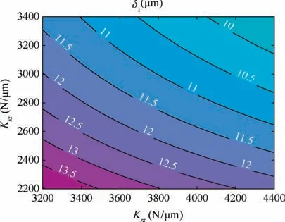
Fig. 12 Variations of δ1 with different Krz and Ksz.
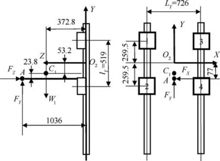
Fig. 13 Supporting diagram of Y direction.
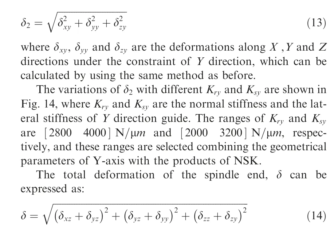
According to the requirement from aero-engine manufacturing companies, δ should be no more than 16 μm. Then,based on Eqs. (12)-(14), the following relation is further given as:

The load along Z direction is about two times than the load along Y direction, and the results shown in Figs. 12 and 13 indicate that δis also two times than δ, thus, the upper boundaries of δand δare determined as:
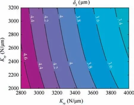
Fig. 14 Variations of δ2 with different Kry and Ksy.

Moreover,the relation between the normal stiffness and the lateral stiffness of guide must meet a certain proportion to ensure that there exist appropriate guides can be chosen,which is expressed as:

Next, Eqs. (16) and (17) are regarded as constraint relations, and based on Figs. 12 and 14, some appropriate solutions can be obtained. Then, combing with the actual products parameters of NSK,the supporting stiffness of guides are determined as:

The corresponding deformations and proportional relations between the normal stiffness and the lateral stiffness are calculated as:

Obviously, the design results meet the constraint relations.
5. Experiments
Based on above work,a prototype of five-axis machine tool for aero-engine casing manufacturing is developed, as shown in Fig. 15, and the detailed selections of the main parts of the machine tool are given in Table 3.Next,a series of experiments is further carried out to validate the actual performance of the machine tool, including performance tests of key components(i.e. the dual drive swing head and the compact motorized spindle), and machining of a simulated workpiece of aeroengine casing.
5.1. Performance tests of key components
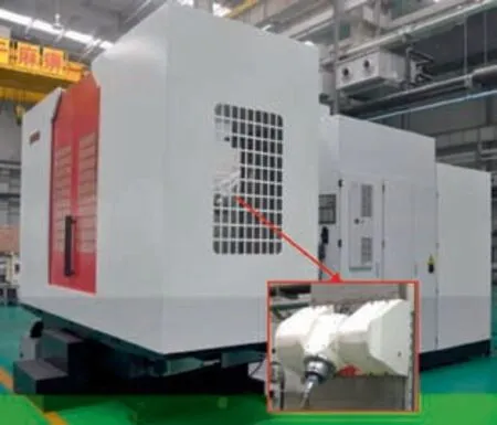
Fig. 15 Prototype of five-axis machine tool for aero-engine casing manufacturing.

Table 3 Detailed selections of main parts of machine tool.
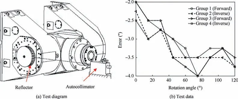
Fig. 16 Positioning accuracy test of dual drive swing head.
The positioning accuracy of the dual drive swing head is firstly tested by using an autocollimator,as shown in Fig.16(a).The reflector with 24 faces is fixed on the external shaft of A-axis,and the swing head performs rotational motion with an interval of 15°. The test is repeated 4 times in the whole swing stroke, and the results are given in Fig. 16 (b), where groups 1 and 3 represent forward motion data, and groups 2 and 4 represent inverse motion data. Based on the standard ISO230-2: 2006,the positioning accuracy of the dual drive swing head can be obtained as 4.414, which is less than the design requirement (i.e. 6).
Next, the radial stiffness of the compact spindle is measured,as shown in Fig.17(a).The sensitively of the force sensor is 2±0.005 mV/V, and the resolution of the inductive displacement sensor is 0.01 μm. The maximum force is within 5000 N,and the measuring results are shown in Fig.17(b).By using the least square method, the radial stiffness is obtained as 304.7 N/μm, and the error between calculation and experiment is only 1.1 N/μm,which validates that the compact spindle has enough stiffness.
Furthermore, the frequency response of the compact spindle is tested, as shown in Fig. 18. A triaxial accelerometer is placed in position 1, which is used to feedback the vibration signals of the three orthogonal directions (i.e. X ,Y and Z),and positions 2 and 3 are the hammering positions. The sensitivities of accelerometer and force hammer are 100.4 mV/g and 0.233 mV/N, respectively.
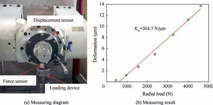
Fig. 17 Radial stiffness measuring of compact spindle.

Fig. 18 Frequency response test of compact spindle.
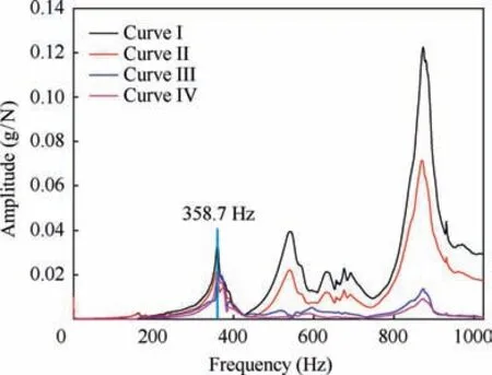
Fig. 19 Frequency response curves of compact spindle.
The test bandwidth is 0-1100 Hz, and the sampling frequency is 2048 Hz. The results are given in Fig. 19, where curves I and II are the responses of X direction when hammering positions 2 and 3, respectively; curves III and IV are the responses of Y direction when hammering positions 2 and 3,respectively. One may see that all response curves have a consistent frequency variation trend, which represents good frequency consistency of the spindle, and the differences of amplitudes are caused by the different hammering positions.The first order natural frequency is 358.7 Hz, and the error between calculation and experiment is only 8.4 Hz. Considering that the actual first order natural frequency of the spindle is 2.69 times over the maximum working frequency, the compact spindle has satisfactory vibration suppression ability.
Besides the stiffness and the frequency response, the dynamic rotation accuracy of the compact motorized spindle is also tested. According to the test standards ISO 230-7:2006 and ANSI/ASME B 89.3.4,the dynamic rotation accuracy test in the full speed range is carried out, as shown in Fig. 20 (a). The measuring range and the resolution of the capacitive displacement sensor are 50 μm and 1 nm, respectively.The length and the roundness of the ball-end test arbor are 1 inch and 50 nm,respectively.During the test process,the speed of the spindle varies from 100 r/min to 8000 r/min with an interval of 1000 r/min, and the synchronous and asynchronous errors are shown in Fig.20(b).It can be seen clearly that all synchronous and asynchronous errors of radial and axial directions are less than 1 μm in the full speed range,which represents very high dynamic rotation accuracy.
Meanwhile, a temperature rise experiment of the compact spindle is performed, and two thermal resistance sensors are put on the temperature measuring points shown in Fig. 8 to measure the temperature of front and rear bearings.The speed of the spindle varies from 4000 r/min to 8000 r/min with an interval of 1000 r/min, and the running time of each speed is no less than 2 min. The experimental results show that the maximum temperature rise is 6.9 ℃, which represents a very low temperature rise in practice and also proves the effectiveness of the cooling system.
5.2. Machining of a simulated workpiece
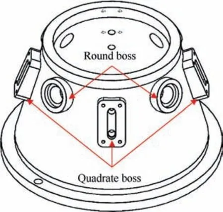
Fig. 21 Simulated workpiece of aero-engine casing.
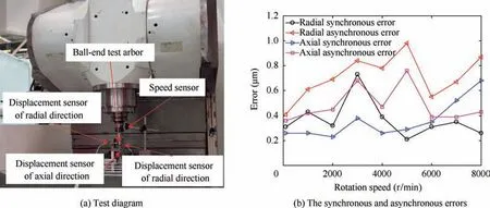
Fig. 20 Dynamic rotation accuracy test of compact motorized spindle.
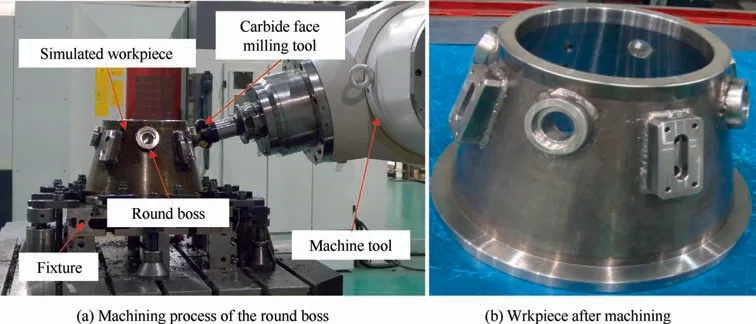
Fig. 22 Machining of simulated workpiece.

Table 4 Detection results of simulated workpiece after machining.
After performance tests of key components,the actual machining ability of the machine tool should be tested. Based on the shape feature and the accuracy requirement of aero-engine casing, a simulated workpiece is designed to validate the actual machining performance of the developed five-axis machine tool, as shown in Fig. 21. The material of the workpiece is stainless steel 1Cr18Ni9Ti,which is hard to process.The round boss and the quadrate boss are the main machining contents,which have the angles of 15°and 20°from the reference plane,respectively.
There are four main stages when machining the simulated workpiece after clamping,including:1)rough milling of round boss and quadrate boss; 2) fine milling of round boss and quadrate boss; 3) drilling of holes; 4) reaming of holes, and each stage contains tool changing, positioning, machining and other assist work. Different tools are selected to complete the machining of the simulated workpiece, and Fig. 22 (a)shows the machining process of the round boss with a 63 carbide face milling tool. The whole machining process is stable and efficient, and the total machining time when completing all stages is less than 15 min. The workpiece after machining is shown in Fig. 22 (b).
The accuracy detection is carried out by using a CMM(coordinate measuring machine),and the detailed results are listed in Table 4.It can be seen that the machined workpiece is qualified, and some detection results are even substantially better than requirements. Thus, the developed machine tool has excellent actual performance, which meets the machining requirements of aero-engine casing in modern aviation industry. Meanwhile, based on the feedback from an aero-engine manufacturing company, the machining time cost of aeroengine casing is reduced about 20%when using the developed five-axis machine tool.Thus,the developed machining tool has higher efficiency than previous machining equipment. On the other hand,because all detection items of the simulated workpiece are within tolerances, the supporting stiffness of guide also meets the requirement proposed in Section 4.
6. Conclusion
A five-axis machine tool for aero-engine casing manufacturing is designed and developed in this paper.The appropriate structure of the machine tool is determined by considering the processing characteristics of aero-engine casing. The drive capability of the swing head is ensured by adopting dual drive form.The compact motorized spindle is designed,and the simulation results by using FEM show that the spindle has desired stiffness and natural frequency.The design method of supporting stiffness of guide is further proposed to limit the deformation of spindle end. The experimental results indicate that the machine tool has satisfactory accuracy,stiffness and efficiency,which meets the machining requirements of aero-engine casing in modern aviation industry. The main work shown in this paper can be used as references for engineers and technicians,which is meaningful in industry.
The authors declare that they have no known competing financial interests or personal relationships that could have appeared to influence the work reported in this paper.
s
This study was co-supported by the Natural Science Foundation of Beijing (No.3214043),the Project of State Key Lab of Tribology of Tsinghua University (No. SKLT2021D16), and the National Natural Science Foundation of China (No.51975319).
