Study of RCS characteristics of tilt-rotor aircraft based on dynamic calculation approach
Zeyang ZHOU, Jun HUANG
School of Aeronautic Science and Engineering, Beihang University, Beijing 100083, China
KEYWORDS Dynamic electromagnetic scattering;Nacelle tilt;Radar cross-section (RCS);Tilt-rotor aircraft;Transition mode
Abstract To study the Radar Cross-Section (RCS) characteristics of the tilt-rotor aircraft, a dynamic calculation approach that takes into account rotor rotation and nacelle tilt is presented.Physical optics and physical theory of diffraction are used to deal with the instantaneous electromagnetic scattering of the target. The RCS of the aircraft in the helicopter mode,fixed-wing mode and transition mode is analyzed. The results show that in the fixed-wing mode, the blade has a weaker deflection effect on the head incident wave in the horizontal plane. The helicopter mode improves the scattering of the rotor in the horizontal plane,while it increases the scattering source on the surface of the nacelle. At a fixed tilt angle, the RCS of the aircraft under a given azimuth angle still shows obvious dynamic characteristics.Dynamic tilting significantly changes the scattering effects of blades, hubs, nacelles and wingtips. The proposed approach is shown to be feasible and effective to learn the electromagnetic scattering characteristics of the tilt rotor aircraft.
1. Introduction
Tilt rotor aircraft has the abilities of vertical take-off and landing, hovering in the air and high-speed cruise flight, which makes it have a broad prospect of application in military and civil aviation. As the tilt transition mode is turned on,the distribution of strong and weak scattering sources near the nacelle of the engine will continue to change under given incident wave conditions.It can be seen that the calculation method of the Radar Cross-Section(RCS)of the tilt rotor aircraft is important for the stealth design and survivability evaluation of this type of aircraft.
The unstructured grid technology is used to assist in calculating the flow field and electromagnetic scattering characteristics of the rotor,and the methods of Physical Optics (PO)and Physical Theory of Diffraction(PTD)are used to calculate the RCS of the main rotor with different shape parameters in a static state.Different from the conventional main rotor and tail rotor, deformation of the tilt-rotor aircraft will significantly change the relative position of the rotor and engine nacelle to the fuselage.The methods of PO and equivalent currents are used to calculate the electromagnetic scattering characteristics of the rotor in the incident wave in the plane of the rotor disk, and the Quasi-Static Principle (QSP) is used to simulate the rotation of the rotor. However, this kind of simulation is difficult to implement on the tilt-rotor because the tilt-rotor aircraft can rotate the nacelle at low speed and rotate the rotor at high speed when maintaining the level of the fuselage.When the rotor of tilt-rotor aircraft is used for horizontal propulsion, the upper surface of the blade and the front of the hub will obviously become the illumination area for the forward horizontal incident radar wave.At this time,the dynamic scattering effect of the rotor is similar to the thrust paddle of the compound helicopter.Same as that in the fixed-wing mode, the forward projection of the engine nacelle is also greatly reduced, thus the comprehensive impact of these changes on the RCS of this aircraft still needs to be resolved.
For the hovering mode, the rotor disc is in the horizontal position, which helps blades to deflect radar waves from the horizontal plane,while the abdomen of the nacelle becomes a new lighting area.The method of PO is used to calculate the RCS of helicopters with and without propellers at different frequencies and pitch angles, showing that the blade will reduce the stealth performance of the helicopter,and the stealth design of the blade shape can improve the stealth performance of the helicopter.Unlike conventional helicopters, the helicopter mode rotor of the tilt-rotor aircraft is at the outer end of the wing, and the rotor radius is smaller than that of the conventional main rotor.Considering different flight missions and modes,the shape of the tilt-rotor will make unique changes, which will affect the deflection of a given electromagnetic wave.It can be seen that the rotation of the rotor, the tilt of the nacelle and the flight mode will all be important factors affecting the electromagnetic scattering characteristics of the tilt-rotor.
Previous research on tilt-rotor aircraft has mostly focused on flow field calculations, aerodynamic optimization and control strategies. However, the research on its electromagnetic scattering characteristics has made little progress. For the related literature on the RCS of helicopter targets,the research is concentrated on conventional helicopters, coaxial helicopters and compound helicopters. PO and quasi-static methods are used to solve the RCS of a single rotor,when the incident wave is parallel to the rotor disk. However, this processing method is suitable for a small number of static state samples, and is inconvenient to obtain a large amount of grid data.The relativistic method is used to simulate the rotation of the rotorby converting the rotation angle into the incident angle of the radar wave,but the method is not applicable to the rotor plus the fuselage or the multi-rotor target.In view of the status quo in these aspects,we establish a Dynamic Calculation Approach (DCA) to determine the electromagnetic scattering characteristics of the tilt-rotor aircraft. Three flight modes, continuous tilting action, and rotor rotation are considered as key influencing factors. The main contribution of DCA is that it can continuously update the calculation model of the tilt-rotor, and it is no longer limited to the situations including single rotor motion or incident waves parallel to the rotor disk. Our study can provide some reference for obtaining the RCS of tilt-rotor aircraft.
The rest of the paper is organized as follows:a dynamic calculation approach is presented in Section 2. The model of the tilt-rotor aircraft is built in Section 3. The results of electromagnetic scattering characteristics of the aircraft are provided and discussed in detail in Section 4. Finally, the full article is summarized in Section 5.
2. Dynamic calculation approach
The schematic diagram of the far-field electromagnetic scattering of the tilt rotor aircraft is shown in Fig.1,where Arepresents the tilt angle of the nacelle, the subscript n1 represents Nacelle 1, and n2 represents Nacelle 2; Arefers to the angle between adjacent blades of the rotor, the subscript r1 represents Rotor 1, and r2 represents Rotor 2; Ais the rotation angle of the rotor, α represents the azimuth angle between the radar station and the aircraft, and β is the elevation angle between the radar station and the aircraft.
2.1. Dynamic scattering calculation
In the far field,the tilt-rotor aircraft is regarded as a scatterer,and its model at the initial moment can be expressed as follows:

where mis the model of the aircraft,t is time,mis the model of Rotor 1, mis the model of Nacelle 1, mis the model of Rotor 2,mis the model of Nacelle 2,and mis the model of the fuselage.
Considering the rotation of Rotor 1, its movement in the current coordinate system can be carried out in the following way:
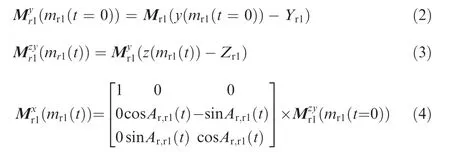
where Mrepresents the grid coordinate matrix of Rotor 1,y is the y axis coordinate value, Yrefers to the distance from the rotation axis of the rotor to the xz plane, and Zrefers to the distance from the rotation axis of the rotor to the xy plane when the tilt angle is equal to 0. Returning the model of the rotating Rotor 1 to the outer end of the wing and then combining it with Nacelle 1, we can get
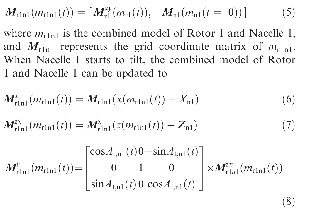
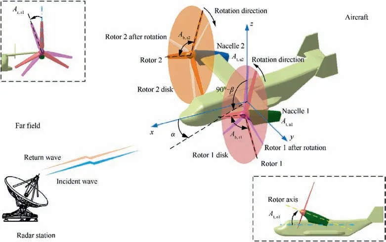
Fig. 1 Schematic diagram of dynamic electromagnetic scattering of tilt-rotor aircraft.
where Xis the distance from the tilt axis of Nacelle 1 to the yz plane, and Zis distance from the tilt axis of Nacelle 1 to the xy plane.Returning the tilted Rotor 1 and Nacelle 1 to the outer end of the wing and simulating the movement of Rotor 2 and Nacelle 2, we can obtain the dynamic model of the tiltrotor aircraft as follows:

where mis the model of the tilt-rotor aircraft, Mis the grid coordinate matrix of the aircraft model,mis the combined model of Rotor 2 and Nacelle 2, Mrepresents the grid coordinate matrix of m, mis the model of fuselage, and Mrepresents the grid coordinate matrix of fuselage model.
Under the irradiation of radar waves, the illuminated area on the aircraft surface can be extracted as

where S(t) is the illuminated area of the aircraft model.
According to the PO method,the far-field electric field formula can be written as
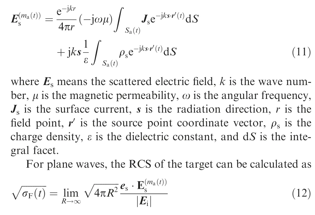
where σ is the RCS, subscript F represents the face element contribution, R is the distance between the field point and the source point,erefers to the direction of the scattered electric field,and Eis the electric field intensity at the point of incidence. For the far field, the RCS calculation formula can be transformed into

Consider the expression for the surface current

where n represents the normal vector outside the surface element, and Hrefers to the magnetic field intensity of the incident point. Considering the relationship between the electric field and the magnetic field, the formula for calculation of RCS can be obtained as

where hrefers to the direction of the incident magnetic field,i is the unit vector of the incident wave, and rrepresents the coordinate vector of the reference point on the integral surface element; I(t) represents an integral expression, which can be obtained according to the following calculation when triangular facets are used

where Lis the vector of the m-th edge on the facet, Arefers to the area of the integral facet,and p represents a defined vector cross product:

PTD is used to calculate the edge diffraction contribution of the target, and for more information about PTD, please refer to Refs.. Therefore, the total RCS can be written as
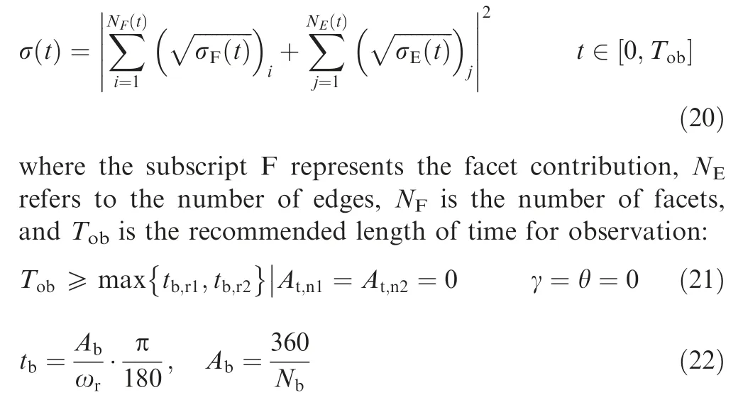
where tis the basic passage time,equal to the time it takes for the blade to rotate through the angle between two adjacent blades,θ is the pitch angle,γ is the roll angle,Nis the number of blades of the rotor, and ωis the angular velocity of the rotor.
To intuitively analyze the scattering characteristics of the target surface, a custom surface scattering intensity can be written as follows:

where I(i) is custom surface scattering intensity, i in brackets is the face number,Kis the color depth control factor,σrepresents the facet RCS under the current condition,σand σrepresent the maximum and minimum of the facet RCS,respectively, and Band Brepresent the upper and lower boundaries of the current color window, respectively.
2.2. Method verification
Validation of the DCA is presented in Fig.2,where frepresents radar wave frequency and horizontal polarization, and nis the rotating speed of Rotor 1.The PO+MOM(Method of Moment)/MLFMM (Multi-Level Fast Multipole Method)in FEKO (FEldberechnung bei Korpern mit beliebiger Oberflache) is used to calculate the RCS of the target under the given conditions. For the RCS curve at t = 4.375 × 10s,it can be observed that the two RCS curves are basically similar, including peak size, curve shape and peak position. The average RCS of DCA curve is 15.24 dBm, which is 0.33 dBmsmaller than that of FEKO curve, and the error is caused by different calculation methods. At 180.5° azimuth,the peak value is over 31.94 dBm, which is mainly due to the surface scattering from the lower surfaces of the blades.These results show that the DCA is feasible and accurate in solving the RCS vs. α curve of the rotor in the transient state.
For the RCS curve at α = 21°, it can be found that DCA curves generally pass through discrete RCS data points determined by FEKO + QSP, where QSP is used to simulate the rotor rotation calculate the RCS vs. t result in combination with conventional methods. The mean RCS of DCA curve is 11.32 dBm, while that of the discrete points obtained by FEKO is 11.65 dBm.The reasons for the error include the difference in calculation methods and the difference in the number of data nodes. The data nodes of the FEKO + QSP curve are significantly less than that of DCA,and it is thus difficult for QSP to deal with a large number of discrete states.For t = 8.188 ms, the DCA curve shows a small peak value of 22.6 dBm, while the small peak value of the other data is 18.31 dBm, indicating that the DCA can show the dynamic RCS characteristics of the rotor more continuously and carefully. These results show that the DCA is effective and accurate in solving the dynamic RCS of the rotor like targets.
3. Model of tilt-rotor aircraft
The model of the tilt-rotor aircraft is built as shown in Fig. 3,where Rand Rrepresent the radii of Rotor 1 and Rotor 2,respectively.Lis the length of the fuselage,His the height of the fuselage, Lis the length of nacelle 2, Lis the length of hub of Rotor 2,Wis the wingspan of the main wing,Wis the distance between the winglets at the tip of the tail,and Yis the distance from the rotary axis of Rotor 2 to xz plane.The main size parameters of the aircraft is presented in Table 1.
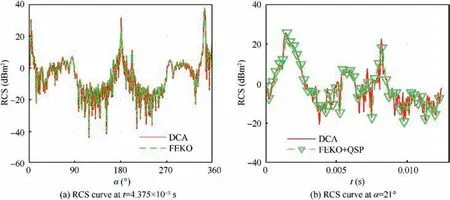
Fig. 2 Validation of DCA on Rotor 1 (fRH = 5 GHz, β = 5°, nr1 = 1600 r/min).
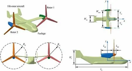
Fig. 3 Establishment of the tilt-rotor aircraft model.
The model of Rotor 1 is presented in Fig. 4, where Ris the radius of the hub of Rotor 1 hub, Ris the radius of Section 1 of the blade, Arepresents the twist angle of the blade root, Arepresents the twist angle of Section 1 of the blade, Arepresents the twist angle of the blade tip, Crepresents the chord length of the blade section, and the numerical subscript represents the position of the section.The airfoil and main dimensions of the rotor are shown in Table 2.
The grid model of the tilt-rotor aircraft is shown in Fig. 5,where the high-precision unstructured grid technology is used to divide the surface of the aircraft.For the local areas such as the leading/trailing edge of blade, blade tip, wing edge, horizontal tail, tail winglet and fuselage edge, the mesh densityincrease technology is adopted. Parameters of the grid size of the typical area are shown in Table 3, noting that the plane geometry of the blade is a two-stage trapezoid.

Table 1 Main size parameter of the aircraft.
4. Results and discussion
Fig. 6 shows that with different radar wave frequencies, the dynamic RCS performance of the rotor at a given azimuth is quite different, including curve shape, peak value and fluctuation. For the RCS curve at f= 1 GHz, it can be observed that the whole curve presents a W shape with many peaks,among which two small peaks of 17.08 dBmand 16.22 dBmappear near t = 6.979 ms. This is because at this time,the rotor rotates 66.998°, making the radial direction of the blade perpendicular to the incident radar wave, and the plane shape of the blade adopts a trapezoidal gradual design.Therefore,the leading edge of the inner trapezoid of this blade is the main strong scattering source of the previous peak 17.08 dBm,while the leading edge of the outer trapezoid is the main contributor to the other peak 16.22 dBm.However,the other small peaks mainly come from the changes in the contribution of the front and rear edges of the inner and outer sections of different blades. Note that when t = 0 s, the rotation angle of the rotor, pitch angle and roll angle are all equal to 0°. As the frequency of the radar wave increases, the fluctuation of the RCS curve gradually increases, and the local peak value also changes. When f= 5 GHz, the peak at t = 6.979 × 1 0s reaches 24.8 dBmbecause the upper surface of the blade and the head of the hub are the main scattering sources. The RCS curve at 11 GHz has a peak of 27.15 dBmat t = 6.97 9 × 10s, and the index at 7 and 9 GHz does not exceed 25.65 dBm. The maximum peak values of these RCS curves are shown in Table 4. Note that the local peak of the RCS curve at 11 GHz is relatively high, while the average value of the dynamic RCS at the current azimuth is as low as 16.6362 dBm. These results show that the radar wave frequency has a significant influence on the dynamic RCS of the rotor at a given azimuth, which is mainly reflected in the mean value,peak value and local fluctuations.
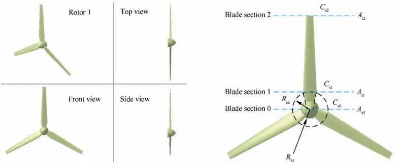
Fig. 4 Model and main geometric parameters of Rotor 1.

Table 2 Main size parameters of the Rotor 1.
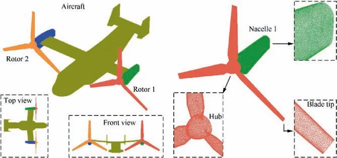
Fig. 5 High-precision meshing of the surface of the tilt-rotor aircraft.

Table 3 Grid size parameters on the surface of aircraft model.
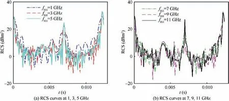
Fig. 6 Dynamic RCS curve of Rotor 1 at different fRH (α = 12°, β = 0°, nr1 = 1600 r/min).

Table 4 Dynamic RCS performance of Rotor 1 at different fRH (α = 12°, β = 0°, nr1 = 1600 r/min).
4.1. Influence of fixed-wing mode
Fig.7 indicates that in the fixed-wing mode,the surface of the blade wing is very easy to become a strong scattering source under the illumination of the forward radar wave. The redder the color is,the larger the RCS here is.For more explanation,please refer to Eq. (23) and its related interpretation. For α = 18° and t = 3.125 ms, it can be observed that the nose,cockpit surface,wing leading edge,belly bulge cabin and blade surface have the highest level of electromagnetic scattering,followed by the side of the fuselage,the nacelle and the tail winglet. When α = 30° and t = 6.25 ms, the rotor has rotated another 30°, but this does not change the fact that there is a large amount of strong scattering on the surface of the blade.This is because the angle between the rotor disk and the incident radar wave at this time is large in fixed-wing mode, and it is thus difficult for the blade to deflect the radar wave to a non-threatening direction. At this time, the azimuth has increased by 12°, and the scattering intensity of the side of the fuselage, the nacelle and the tail winglet has been significantly improved. These results show that the DCA is intuitive and effective when used to evaluate the electromagnetic scattering characteristics of the tilt-rotor aircraft in the fixedwing mode.
Fig.8 shows that the dynamic RCS of the aircraft at different azimuths is obviously different, including the overall level,peak value and curve shape.In terms of the RCS curves at various α, the RCS curves at 12° and 15° azimuth angles are roughly similar, and the average values are 20.7811 dBmand 21.5926 dBm, respectively. However, the RCS mean of the curve at 25° azimuth is as low as 10.6739 dBm, because at this time the angle between the rotor disk and the radar wave has been better improved. For the RCS curve at 15°azimuth,the dynamic electromagnetic scattering characteristics of the aircraft in the fixed-wing mode are still very obvious, with the maximum value reaching 34.39 dBmand the minimum value being close to -6 dBm. This is because the three blades of the rotor are constantly deflecting radar waves, while the fuselage and nacelle enhance the RCS level of the entire aircraft. For the RCS curves at various t, it can be noticed that there are many similarities in the RCS curves of the airplanes at different times, including the average value and the peak value, and the RCS mean of the curve at t = 1.979 ms is 24.2238 dBm, and that at t = 8.229 ms is 24.6063 dBm.However, the local fluctuations of the three RCS curves are quite different, including in the azimuth range of 0° to 21.5°,57.75°to 81.25°,161.5°to 198.8°and 327.3°to 358.25°.These results indicate that the electromagnetic scattering characteristics of this aircraft in the fixed-wing mode exhibit complex dynamic characteristics due to rotation of the rotor.
It can be seen from Fig.8(c)and(d)that the periodic characteristics of the tilt-rotor RCS are significantly different from those of the single-rotor RCS, and Nis the multiple of the blade base passing time. For the single Rotor 1, the minimum period of RCS is equal to 1 times the basic passage time of the blade, which is 0.0125 s. For the tilt rotor aircraft, the minimum period of RCS is equal to 3 times the basic passage time of the blade.This is because when the blades of the two rotors have completed an Ab angle of rotation, they will enter the next Ab cycle under the current conditions.
4.2. Influence of helicopter mode
Fig. 9 manifests that in the mode, the side and head RCS curves still show obvious dynamic characteristics. The RCS curve at α = 10° basically fluctuates in the range of 5.819 dBmto 14.33 dBm, and the average here is 12.0868 dBm.For the RCS curve at α=20°,the peak is 13.95 dBm,appearing at 9.375 ms,and the RCS mean is 10.0813 dBm.It can be observed that the RCS curve at α = 30° fluctuates the most,and the average value is only 2.3097 dBm. This is because the incident angle of the radar wave at this time balances the angle between it and the fuselage and wing, and the dynamic scattering effect of the rotor can be expressed. For the side incident, the difference in the levels of the three RCS curves is relatively obvious, where the RCS mean of the curve at α = 70° is 17.9081 dBm, while that at α = 90° is 28.4201 dBm. This is because facing the incident radar wave at 90°,the side of the fuselage, nacelle and tail winglet constitutes the basic highest strong scattering source, and the blades and hub provide the dynamic change of the RCS of the aircraft.These results show that the DCA can well show the different changes of aircraft RCS at different observation angles in the helicopter mode.
It can be seen from Fig.10 that the local fluctuation of the aircraft RCS curve at different times are different,but the RCS levels are similar. For the curve at 1.458 ms, the peak is 29.43 dBmappearing at α = 90°, and the RCS mean is 11.7995 dBm. In the range of 37.5° to 63.25°, 153° to 295.5° and 301.8°to 344.5°azimuth angles,the curve at 3.542 ms is obviously different from that at 6.146 ms. This is because in the current mode, contribution of the dynamic RCS from the upper surface of the rotor blade cannot be ignored although the angle between the rotor disk and the radar wave is small.For the RCS curve at t = 9.271 ms, the peak value is 28.09 dBmat 90° azimuth, and the RCS mean is 11.642 dBm.When t=1.031 ms,the RCS curve has some minimum values,and there are several small peaks exceeding 16.05 dBmnear 230.75° azimuth. These results show that there are differences in the RCS vs. α curve at different times in the helicopter mode, but the peak and average values are close.
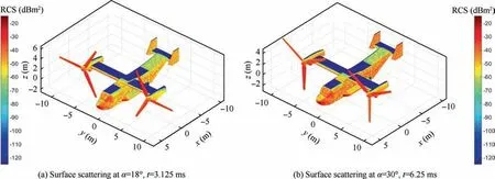
Fig. 7 Surface scattering of the aircraft (fRH = 5 GHz, β = 0°, nr1 = nr2 = 1600 r/min, RCS unit: dBm2).
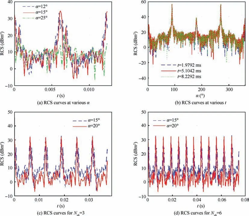
Fig. 8 RCS curve of the aircraft (fRH = 5 GHz, β = 0°, nr1 = nr2 = 1600 r/min).
4.3. Influence of fixed tilt
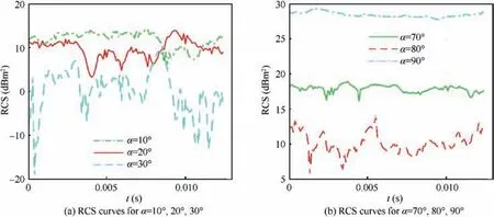
Fig. 9 Dynamic RCS of the aircraft at various α (fRH = 5 GHz, β = 10°, nr1 = nr2 = 1600 r/min).
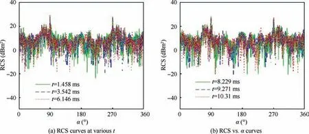
Fig. 10 Dynamic RCS of the aircraft at various t (fRH = 5 GHz, β = 10°, nr1 = nr2 = 1600 r/min).
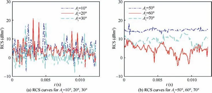
Fig. 11 Dynamic RCS of the aircraft at various At (fRH = 5 GHz, α = 27°, β = 0°, nr1 = nr2 = 1600 r/min).
Fig.11 reveals that the RCS of the aircraft at different fixed tilt angles still shows different dynamic characteristics. For the RCS curve at A= 10°, the curve fluctuates greatly between-7.84 dBmto 18.62 dBm, resulting in an average value of 7.135 dBm. As the azimuth gradually increases to 30°, the fluctuation range of the RCS curve does not decrease, but the mean value decreases more.The RCS mean of the curve at A= 20° is 6.562 dBm, and that at A= 30° is 4.667 dBm.This is mainly due to the reduction of the angle between the rotor disk and the radar wave,which makes the strong scattering source on the surface of the blade weaker.When A=50°,the entire RCS curve has smaller fluctuations around 14.733 dBm, and the maximum peak value reaches 18.61 dBm.When A= 60°, the RCS mean of the curve is as low as 5.06 dBm, while that indicator at A= 70° increases to 9.701 instead. This is because at this time, the rotor is still the source of dynamic RCS, but the exposure of the nacelle belly is the main contribution to the increase in RCS level.These results indicate that the average RCS index of the aircraft at a given azimuth will dynamically change with the increase of the tilt angle.
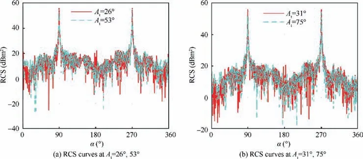
Fig. 12 RCS curve of the aircraft at various At (fRH = 5 GHz, t = 2.708 ms, β = 0°, and nr1 = nr2 = 1600 r/min).
Fig.12 shows that there is a slight difference in the RCS vs.α curve of the aircraft at the given tilt angles.For A=26°,the entire RCS curve presents an M shape, with peaks exceeding 56.13 dBmat both 89.75° and 270.3° laterally, and the RCS mean is 31.903 dBm.The curve for A=53°is similar to that for A= 26°, and the difference is obvious in the azimuth range of 4.25° to 77.75° and 285.8° to 353.25°. When A= 75°, the RCS mean of the curve increases to 32.027 dBm, which is significantly higher than this indicator of the other three curves. This is because at this time, the sides of the propeller hub, abdomen and nacelle and the outside of wings are all new strong scattering sources. These results indicate that the average RCS index of the aircraft will be intuitively increased at a larger tilt angle.
4.4. Influence of dynamic tilt
Fig. 13 shows that the tilt angle can significantly change the intensity of the scattering source on the surface of the rotor and the nacelle. When α = 13° and t = 5.7 s, it can be observed that the blades and the front of the nacelle still have a relatively high RCS. This is because the angle between the rotor disk and the incident radar wave is large at this time,and the curvature of the front surface of the nacelle is not conducive to deflecting the radar wave.Under current conditions,the electromagnetic scattering characteristics of the nose and the cockpit are strong.For α=29°and t=13.2 s,the surface of the blades has transformed from the original red to orange and yellow,the red of the hub has been slightly deepened,and the red area of the nacelle has been greatly increased. This is because at this time, the angle between the rotor disk and the incident wave has been reduced more, and the angle between the nacelle belly and the radar wave has been increased. These changes directly affect the scattering effect of the upper elements in these areas.Under current conditions,the azimuth is increased, which leads to the enhancement of the electromagnetic scattering characteristics of the sides of the fuselage and the surface of the tail.These results show that the DCA can well capture the changes in the electromagnetic scattering characteristics of the aircraft surface with dynamic tilting.
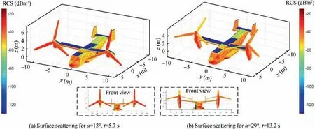
Fig. 13 Surface scattering of the aircraft (fRH = 5 GHz, β = 0°, nr1 = nr2 = 1600 r/min, ωn1 = ωn2 = 8.727 × 10⁻² rad/s).
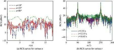
Fig. 14 RCS curve of the aircraft (fRH = 5 GHz, β = 0°, nr1 = nr2 = 1600 r/min, and ωn1 = ωn2 = 8.727 × 10⁻² rad/s).
Fig.14 shows that dynamic tilting has a significant effect on the RCS ~α and RCS ~t curves of the aircraft.For the RCS curve at α=18°,the RCS mean is 15.8217 dBmand the peak reaches 35.0529 dBm,where the whole curve has a large range of changes and many fluctuations. When α = 25°, the RCS curve fluctuates violently between -5.351 dBmto 18.53 dBm, and the RCS mean is 12.2176 dBmand the peak is 18.5255 dBm. When α = 80°, the curve fluctuations are generally relatively flat, and the mean of the RCS curve has increased to 17.7262 dBm, because at this time, the dynamic scattering effect of the engine nacelle occupies the main position. In terms of the RCS curves at various t, it can be observed that the peak size and position are basically the same,but the curve shape is quite different,which leads to the difference in the RCS average index. The mean of the curve at t = 5.55 s is 7.4411 dBmand the peak reaches 56.145 dBm, while the RCS mean at t = 12.15 s is 10.6812 dBmand that at t = 16.65 s is 9.7228 dBm. This is because with the gradual increase of time,the rotor and nacelle gradually tilt and approach the vertical position,which makes the scattering characteristics of the nacelle,rotor hub,blade tip and wing tip significantly enhanced.These results show that dynamic tilting brings significant changes to the peak RCS at a given azimuth and the average RCS at a given time.
5. Conclusions
Based on the proposed dynamic scattering calculation method,the radar characteristics of the aircraft in the helicopter mode,fixed-wing mode and tilt mode are studied.The following conclusions can be drawn:
(1) In the fixed-wing mode, blades will always be a strong scattering source for head incident waves in the horizontal plane,while the fuselage and nacelle will significantly improve the RCS level of the whole machine.
(2) The helicopter mode can improve the electromagnetic scattering effect of the rotor in the horizontal plane,but makes the nacelle of the engine a new strong scattering source,thereby increasing the average RCS index of the aircraft.
(3) With a fixed tilt angle, the RCS of the aircraft with different azimuth angles still shows different dynamic characteristics, and the average RCS of the aircraft with a larger tilt angle will increase.
(4) Dynamic tilting will obviously affect the electromagnetic scattering characteristics of blades, hubs, nacelles and wing tips. The peak and mean of the aircraft RCS at a given azimuth, and the mean of the aircraft RCS at a given time will change significantly with the increase of the tilt angle.
The authors declare that they have no known competing financial interests or personal relationships that could have appeared to influence the work reported in this paper.
This work was supported by the Project funded by China Postdoctoral Science Foundation (Nos. BX20200035,2020M680005).
