Heat transfer characteristics in a narrow confined channel with discrete impingement cooling
Yng LI, To LIU, Jinjun TAO, Weihu YANG, Likun DONG
a Hunan Key Laboratory of Turbomachinery on Small and Medium Aero-Engine, AECC Hunan Aviation Powerplant Research Institute, Zhuzhou 412002, China
b College of Energy and Power Engineering, Nanjing University of Aeronautics and Astronautics, Nanjing 210016, China
KEYWORDS Aero-engine;Heat transfer characteristics;Impingement cooling;Narrow confined channel;Turbine blade
Abstract Heat transfer characteristics in a narrow confined channel with discrete impingement cooling were investigated using thermal infrared camera. Detailed heat transfer distributions and comparisons on three surfaces with three impact diameters were experimentally studied in the range of Reynolds number of 3000 to 30000. The experimental results indicated that the strong impingement jet leaded to a high strength heat transfer zone in the ΔX=±2.5Dj range of the impact center,which was 1.3-2.5 times of the average heat transfer value of the impingement wall.With the same coolant mass flow rate, small diameter case had lower heat transfer coefficient on both inner wall and outside wall, while the impingement wall was insensitive to the impact diameter. The surface averaged Nusselt number of inner wall was only 43%-57%of impingement wall,while the outside wall can reach up to 80%-90%.The larger the diameter,the higher heat transfer enhancement and the smaller the channel flow resistance was observed in term of Reynolds number.The surface averaged Nusselt numbers were developed as the function of Reynolds number and the impingement height-to-diameter for further engineering applications.
1. Introduction
Increasing the inlet temperature of the turbine is one of the key ways to develop high performance aero-engine.Due to the high gas inlet temperature, thermal protection techniques,including internal cooling and external coating, are applied in turbine blades.Among many internal cooling schemes,impingement cooling is one of the best cooling techniques for engineering application.
For past decades, lots of researches have been devoted to impingement cooling,including single-hole jet impingement,in-line jet impingement,and two-dimensional array jet impingement.Impingement cooling is first used for turbine vanes, but also for turbine blades as the heat load increases.In turbine rotor blades,due to the requirement for the connection strength of partitions, the application of impingement cooling is limited,mainly focusing on the blade leading edge,blade tipand trailing edge region.The application of impingement cooling in rotor blade is mainly to realize the high local cooling efficiency at high heat load area.
The impingement cooling applied in the mid-chord of the blade, also known as the double-wall cooling,is a kind of cooling in the confined space,and its impingement distance is small,which has unique impact flow and heat transfer characteristics.The double-wall cooling is mainly used in the first stage rotor blade of large thrust engines or high-power engines. The size of the blade is appropriate for double-wall design and the mass flow of coolant is enough for in-line jet impingement or array jet impingement application.
For most impingement cooling researches, the major concerns were the heat transfer performance of impingement target plate.The key parameters,such as the impingement hole diameter,the impingement jet angle,jet-to-target spacing,jet-to-jet spacingand the wall roughness,have been extensively reported for impingement target plate.Among these factors, the jet-to-target spacing is one of the most important factors affecting heat transfer on target surface. In general, a suitable impact distance is favorable for surface heat transfer enhancement.
The performance of heat transfer characteristics in real double-wall cooling structure is the hot spot in the application of impingement with film cooling.The effect of channel dimensions and hole spacing,as well as cross flow on target wall heat transfer were compared in a double wall cooling scheme.Heat transfer correlations were developed based on local jet Reynolds numbers with a variety of applications. Also, the cool-side augmentation and impingement jet arrays in a double-wall cooling of a full-coverage effusion plate were investigated for engineering application reference.The configuration of impingement target plates,the cross-flow schemeswere adequately studied in double-wall cooling structure with film effusion holes. The heat transfer on the whole target plate was obviously enhanced by jet Reynolds number in all cases.
On the other hand, the application of special-shaped film holes is also the key means to improve the cooling effect of turbine blades. There is a certain research foundation for the special-shaped film hole, such as the sister-hole film cooling,double-jet film-coolingand super-elliptical holes,which have been investigated to obtain higher cooling efficiency. It was found that the special-shaped film hole induced kidney vortex enhanced the coolant interaction which further provides better cooling performance. And the manufacturing technology of these film holes needs to be further solved. In further application, the double-wall impingement cooling structure combined with special-shaped film cooling is the key technology to realize high thermal cycle parameter engine.
As the heat transfer capacity of the target surface gets higher, the higher cooling efficiency can be obtained. But it also easily leads to the excessive temperature stress of the blade cross section.The fine cooling design needs to pay more attention to the heat transfer characteristics of the inner wall,which refers to the partition where the impact hole is located.
This study aims to provide important new experimental data for confined impingement cooling with discrete holes which have never before been considered, in order to expand the range of applicability of current analytical correlations,and for development of new impingement design models. Of interest within the present investigation are the effects of impingement jet Reynolds number, three surface heat transfer distributions and stream-wise heat transfer development.
2. Experimental setup
2.1. Experimental model
In this paper, the experimental model is simplified from the turbine blade with double-wall cooling scheme in mid-chord region. The typical characteristic is the impingement in film cooling in confined channel. The schematic of test section is shown in Fig. 1. The cross-section of heated channel is a rectangle with a height of 80 mm and a width of 20 mm. The length of heated section is 410 mm, while a 175 mm unheated entrance locates before the channel inlet. The impingement plate is simplified from the inner wall of double-wall structure,and the film plate is corresponding to the outer wall.In current study, the inner wall and outside wall of impingement plate,and the impingement wall of film plate were heated for heat transfer test.
Seven round impingement holes with diameter(D)of 6 mm(basic case), are discretely drilled on the impingement plate.Four impact holes in the first row locate at Y/D= 3.3, and the three impact holes in the second row locate at Y/D= 10. The stream-wise (X direction) spacing of the first row of adjacent impact holes is ΔX/D=17.35 and the second row is 21.67. The impingement height is 6 mm which leads to Z/D= 1.0. A column of 12 outflow holes with diameter of 4 mm are arranged at the center line of the film plate, with the flow angle of 45°.
Modular design method is applied in the experiment,which can realize the experimental study of different impact hole parameters by replacing the impingement plate, and can also realize different impact spacing by adjusting the gasket height between the impingement plate and the film plate.To study the effect of impingement hole, five additional cases including D= 4 mm to D= 9 mm were tested in current study by replacing the impingement plate.
Based on the experimental model, the coolant flows through the rectangular channel and enters the impingement chamber through the impact holes distributed along the flow direction, which produces intense heat transfer on the impact target surface(film plate),and finally discharges from the outflow film holes. The heat transfer characteristic on the inner wall and outside wall of impingement plate, and the impingement wall of film plate are the focus of this study.
2.2. Experimental system and test scheme
The experimental apparatus is shown in Fig.2.The experimental system includes the main flow path arrangement, the heating system of test section, the pressure measurement system,the temperature measurement system and the data processing system. High pressure air above 0.5 MPa is provided through air compressor.The first mass flow-meter and the electric heater are placed before the mainstream enters the test section.
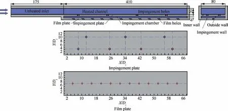
Fig. 1 Schematic of test section.
A pressure stabilizer tank is arranged in the experimental section to ensure the stability of the mainstream pressure and flow field into the experimental piece. The electric heated film on the test plates of the experimental section are heated by DC power supply, and the real-time temperature measurement is carried out by infrared thermal imager. At the same time, a number of thermocouples are arranged on the experimental piece to measure the wall temperatures of the heat transfer surface and the fluid temperatures at the inlet and outlet of the test channel.The second flow-meter is arranged at the mainstream outlet to calibrate the mass flow rate of the flow path twice.
The test schemes of three heated wall is shown in Fig. 3.Due to the limitation of geometric structure,heat transfer tests are carried out on three heating surfaces separately. The electric heated film is custom-made and pasted on the test wall by high thermal conductivity silica gel. Thus, the heating boundary of the heated wall is iso-flux.For the inner wall and outside wall of impingement plate, the infrared thermal imager needs to pass through a layer of transparent plate which is made of plexiglass to obtain the temperature field of the heating surface. For the impingement wall of film plate, the wall temperature is tested through two layers of transparent plate.In heat transfer tests,each heating surface is equipped with three thermal resistors for wall temperature test and infrared calibration.The three sensors are arranged equidistant along the flow direction. The calibration of infrared camera was operated in both heat loss tests and heat transfer tests. The temperature results of infrared camera and thermal resistance are corresponding in real time, and the calibration of test results can be realized.
3. Data reduction
3.1. Parameters calculation
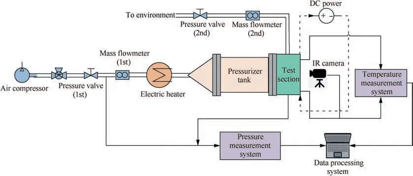
Fig. 2 Experimental apparatus.
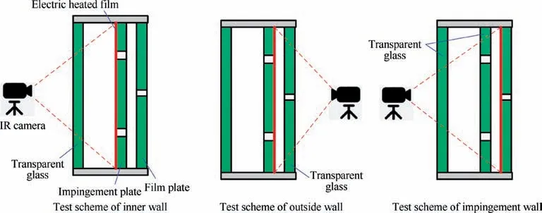
Fig. 3 Test schemes of three heated walls.
The heat transfer coefficient is calculated by considering the net heat flux transferred to the coolant from the target surface.As previously mentioned, the electronic film heater, mounted on the target plate, was used as the heat source. The power to the electronic film heater is controlled and regulated using a DC power supply. Thus, the thermal boundary of test wall is iso-flux. Heat loss calibration tests were separately performed to determine the external heat losses for each heated plate at three wall temperature levels (T= 315, 330,345 K).In heat loss calibration tests,the temperature of target plates were measured by several thermal resistors attached on the heated wall. In heat transfer experiment test, the temperatures of these thermal resistors are used as calibration reference for infrared temperature.

where h is the heat transfer coefficient; Qis the net heat energy of the wall; Tis the wall temperature; Tis the fluid reference temperature; A is the area of the wall heat transfer surface; I is the current of the film heater; R is the resistance of the film heater;his the heat loss coefficient of each heated wall;Tis the wall temperature of each heater;Tis the environment temperature. The global bulk mean temperature is calculated by arithmetic mean of inlet and averaged outlet fluid temperature of each film hole.

where Tis the channel inlet temperature; Tis the outlet fluid temperature of each film hole;N is the number of the film hole. The impingement Reynolds number Rewas employed for coolant flow indication,which can be calculated as follows:

where ρis the fluid density;Dis the diameter of the impingement hole;Uis the velocity of the impingement hole; ˙mis the mass flow rate of the coolant fluid; Ais the area of the impingement holes; μ is the molecular dynamic viscosity of fluid. The Nusselt number can be calculated:

where λ is the thermal conductivity of fluid.It should be noted that the diameter of impingement hole (D) is used as the geometrical feature scale for Reynolds number and Nusselt number calculation, which is appropriate for the outside wall and impingement wall. For inner wall, the hydraulic diameter of the rectangular heated channel is more commonly used. However, in current study, in order to compare the different heat transfer strength on these three surfaces,the same geometrical feature scale (D) is applied for all the cases.
For the entire channel, Fanning friction factor was used to measure the flow resistance loss of the coolant flow.

Here,the inlet static pressure(P),density(ρ)and coolant velocity (U) were defined at the inlet cross-section of the heated channel, while the outlet static pressure (P) was defined at the exit of film hole.
3.2. Parameters range and uncertainty
The uncertainty analysis was performed based on the method described by Kline and McClintock.The measurement accuracy of the thermal resistors can reach to±1.0 ℃and pressure sensor is ± 0.075% indication, and the mass flow rate is ± 1.0% indication. Therefore, the maximum uncertainty of Reynolds number is 2.4% of the present data, and the uncertainty of Nusselt number varies from 5.8% to 13.7%.Systematic errors and random effects are not included in this process, and all the uncertainty analysis only concerns limited precision.
The experimental conditions are listed in Table 1.
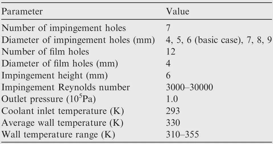
Table 1 Experimental conditions.
4. Results and discussion
4.1. Data validation

4.2. Heat transfer distributions in stream-wise direction
Impingement cooling is a kind of local enhanced heat transfer mode. The heat transfer distributions on impingement surface often show typical peak-valley distribution characteristics.This feature is more obvious in discrete impingement cooling presented in current study.
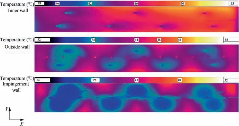
The wall temperature contours on three heated surfaces of basic impingement hole diameter of 6 mm with Reynolds number of 6000 are presented in Fig. 5. It can be clearly observed that there is a significant low temperature region near the impingement holes for three surfaces due to the outflow or impingement of the impingement holes. The low temperature region actually corresponds to the high heat transfer region of the wall.
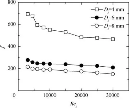
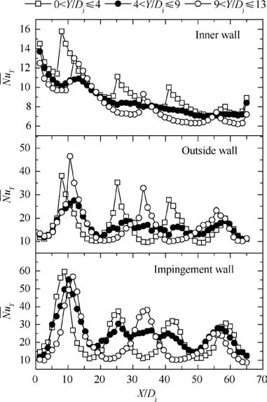
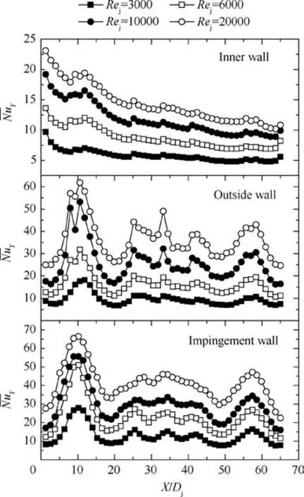
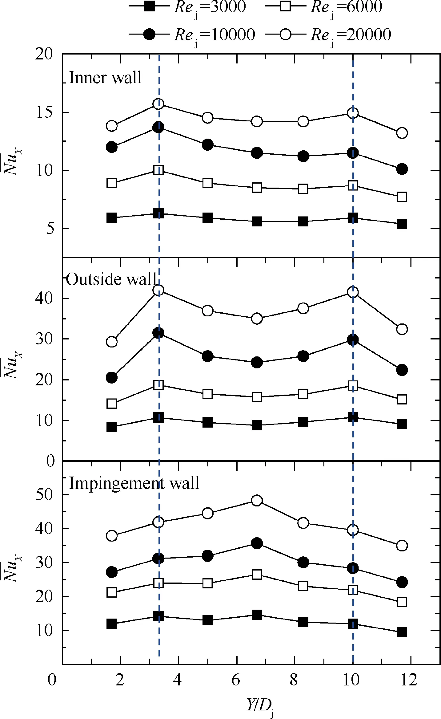
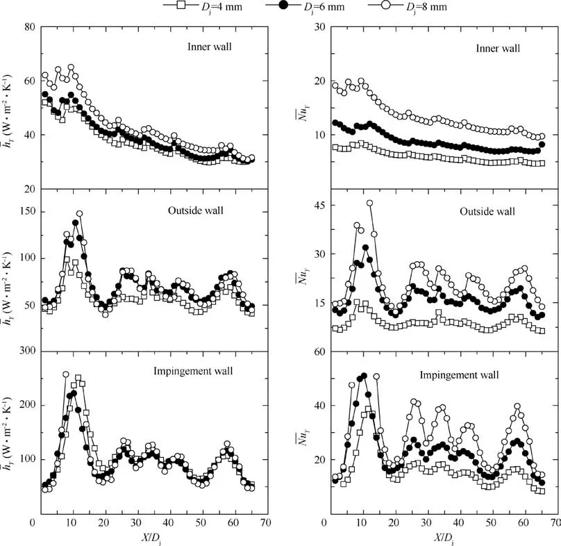
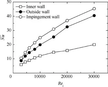
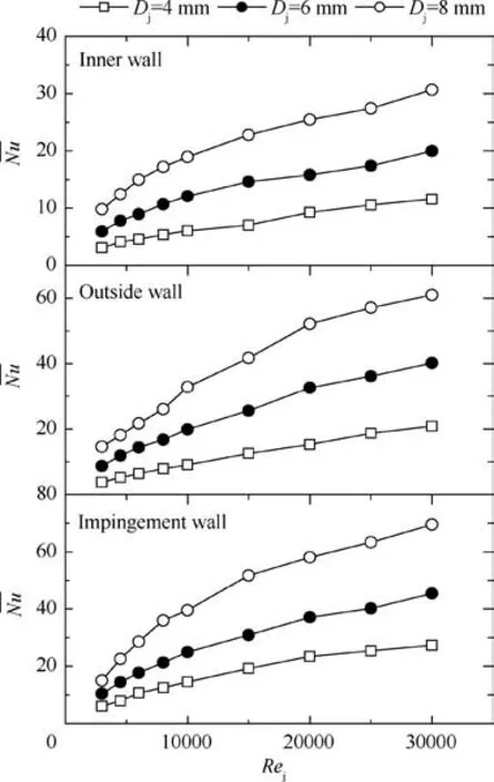
Three span-wise regionally averaged Nusselt numbers on three heated surfaces are shown in Fig. 6. This set of heat transfer data correspond to the experimental conditions with a Reynolds number of 6000 when the diameter of impingement hole is 6 mm. Due to the impingement holes locate at Y/D= 3.3 and 10, the 0 < Y/D≤4 and 9 < Y/D≤13 cases represent the impact area of the first and second rows of impingement holes,respectively.The 4 Fig. 4 Distributions of span-wise regionally averaged Nusselt numbers on impact target surface (Rej = 20000, Dj = 4 mm). For inner wall of impingement plate, the flow pattern is to draw out the coolant along the discrete impingement holes.Therefore, the heat transfer distribution tends to decrease along the stream-wise direction and is significantly influenced by the outflow holes, showing a typical local heat transfer enhancement. Compared to the 4 < Y/D≤9 case, 0 < Y/D≤4 and 9 < Y/D≤13 cases show 20%-60% higher heat transfer enhancement around the outflow holes. Meanwhile,10-20% lower heat transfer is observed between two adjacent impingement holes of the same row. As the coolant passes through the impingement holes into the impact chamber, the heat transfer on the impact target plate is greatly enhanced. The outside wall of impingement plate, subjected to strong impingement coolant reflux in confined space, and the heat transfer distribution is basically consistent with the impact target surface.According to the singlejet impingement flow morphology,the impingement flow is far from fully diffused in such confined channel (Z/D= 1.0).Thus, the stagnation region is much smaller, and the strength of secondary flow in cross-section is stronger. The 4 < Y/D≤9 case also presents typical heat transfer peak-valley distribution on outside wall. In addition to the region near the impact holes closest to the inlet section, the heat transfer strength of the other areas is basically the same level, which indicates that the coolant mass flow rate of each impingement holes is similar. It can be estimated that the region near the first impingement hole presents 20%-30%higher heat transfer strength than other stream-wise regions. For the impingement wall, the purpose of impingement is to achieve the strongest heat transfer enhancement. The regionally averaged Nusselt numbers in stream-wise distribution at 0 < Y/D≤4 and 9 < Y/D≤13 cases coincide with the position of the impingement hole.In this confined channel,the strong impingement jet leads to a high strength heat transfer zone in the ΔX=±2.5Drange of the impact center. For the first impingement hole,the heat transfer in the impact center area is more than 2.5 times the average heat transfer value of the impingement wall. In the downstream impingement holes, the central strengthening effect decreases rapidly to 1.6-1.3 times. Influenced by side impinging jets, the 4 < Y/D≤9 case presents strong heat transfer near the first impingement hole area,which is then equal to the average heat transfer level of the impingement wall. The span-wise averaged Nusselt numbers with four Reynolds number cases on three heated surfaces are shown in Fig. 7. The diameter of impingement hole is 6 mm. The decreasing trend of heat transfer along the stream-wise direction is consistent in different Reynolds numbers for inner wall.The enhanced effect of the outflow holes is more obvious under the condition of high Reynolds number (e.g.Re=20000),especially in the area near the first impingement hole. The span-wise averaged Nusselt number distribution show the same tendency for both outside wall and impingement wall.The effect of secondary flow on the outside wall is enhanced synchronously with the increase of Reynolds number. For impingement wall, with the increase of Reynolds number, the heat transfer augment in the impingement center area is not as strong compared with surface averaged heat transfer. For example, at X/D= 10.2, the heat transfer enhancement is 2.2 times of the average value at Re=3000,and this enhancement decreases to 1.6 as Reincreases up to 20000. At X/D= 57.4 near the end-wall of the channel, the peak-toaverage heat transfer enhancement is 1.27 at Re= 3000 and 1.14 at Re= 20,000, respectively. Fig. 5 Wall temperature contours on three heated surfaces (Rej = 6000, Dj = 6 mm). This is mainly due to the different strength of cross flow induced by the discrete impingement in such confined channel at different Reynolds numbers. In low Reynolds cases, the induced cross flow effect is weak, leading to the lower average heat transfer level of the impingement surface. As Reincreases, a large number of impact jets cannot flow out of the film holes quickly, which improves the average heat transfer level of the impingement wall and the outside wall of the impingement plate. Fig. 6 Distributions of span-wise regionally averaged Nusselt numbers on three heated surfaces (Rej = 6000, Dj = 6 mm). Fig. 7 Distributions of span-wise averaged Nusselt numbers with four Reynolds number cases on three heated surface(Dj = 6 mm). For inner wall, the Nusselt numbers at Y/D= 3.3 and Y/D= 10 show 5%-15% enhancement than the surface averaged value. And the heat transfer of adjacent regions (Y/D= 1.7 and Y/D= 5.0) of the outlet holes shows similar heat transfer levels because of the circumferential effect of outflow holes.On outside wall,in addition to the high heat transfer zone where the impingement holes are located, the heat transfer between the two rows of impingement holes is much higher than that near the corner area of both sides. It should be noted that the outlet film holes are arranged in the middle position of the film plate, and their suction effect on the coolant inevitably leads to stronger secondary flow between the two rows of impact holes, while the flow in the corner area of both sides is weak. For impingement wall, the suction effect of film holes in span-wise direction is more obvious. The highest heat transfer point appears in the middle of the impingement wall rather than the location of impingement hole. It is interpreted that the peak heat transfer enhancements caused by impingement holes were wiped out in stream-wise averaged process due to the discrete arranged holes only directly affect a smaller region(±2.5D)in such confined channel.That is,the position of the film holes dominates the migration to the strongest heat transfer position on the impact surface. This can be used as an important guide in engineering design. Fig. 8 Distributions of stream-wise averaged Nusselt numbers on three heated surfaces (Dj = 6 mm). Also, the highest stream-wise averaged Nusselt numbers of outer wall and impingement wall show 12%-20%higher than surface averaged value. This indicates that the span-wise heat transfer difference is limited and it is benefit for the reducing the wall temperature gradient in span-wise direction. The diameter of impingement hole is a key parameter is impingement cooling. Heat transfer distributions with three diameter cases are selected for comparison, as are shown in Fig. 9. In order to better compare the heat transfer capacity under different diameters of impingement hole, the conditions of the same coolant mass flow rate are applied.Thus,the Reynolds number is 6000,with D=6 mm,and turns to 9000 and 4500 for D= 4 mm and D= 8 mm, respectively. It was observed that, the diameter of impingement hole evidently affects the heat transfer coefficient on inner wall due to the different strength of induced suction effect.Compared to D=6-mm case,the D=4 mm case presents 5%lower heat transfer coefficient while the D= 8 mm case is improved 13%. On outside wall, the D= 6 mm case and the D= 8 mm case show almost the same heat transfer coefficient distributions, while the D= 4 mm case presents 20% lower heat transfer level. It is assumed that the smaller hole diameter causes smaller reflux vortex and the influence on heat transfer of the outside wall is weakened to some extent.As the diameter increases to a certain extent(e.g.D=6 mm),the reflux vortex in the impingement chamber is constrained by space and cannot continue to develop,so the influence on heat transfer of the outside wall is almost disappeared. For impingement wall, the heat transfer coefficient distributions are almost the same for these three diameter cases. This indicates that the combined effect of impingement and film outflow extraction under the same coolant mass flow rate leads to the same heat transfer enhancement on this impingement wall. For averaged Nusselt number, larger impingement hole diameters present evidently higher heat transfer distribution for all these three surfaces. For double-wall cooled turbine blade design, both sides of the impingement plate is wrapped by the coolant. The lower the heat transfer coefficient, the more favorable it is to reduce the cross-section temperature gradient which is beneficial for blade strength.From this point of view,the small impingement hole diameter is favorable, and the heat transfer coefficient of the impingement surface under the small diameter is equivalent to the value of the large diameter at the same coolant mass flow rate. However, smaller diameter will inevitably lead to greater loss of coolant resistance, which will be presented in subsequent results. Fig. 9 Distribution of span-wise averaged heat transfer coefficients and Nusselt numbers on three heated surface based on same coolant flow rate. Fig. 10 Effect of Reynolds number on surface averaged Nusselt numbers for three surfaces (Dj = 6 mm). The coefficients for the correlation function are shown in Table 2. It should be noted that the data fitting also includes three other groups of diameter conditions (D= 5, 7, 9 mm)which are not detailed presented in this paper. Fig.11 Effect of Reynolds number on surface averaged Nusselt numbers for three diameters of impingement holes. The channel resistance for three diameters of impingement holes is presented in Fig. 12. As Reynolds number increases,the channel flow resistance decreases gradually until to a flat trend. The larger the diameter, the smaller the channel flow resistance is observed. As the diameter of impingement hole decrease to D= 4 mm, the channel flow resistance turns 2.0-2.5 times of D= 6 mm case, while the D= 8 mm case is only 75% of the basic case. Therefore, given the same coolant mass flow rate,the larger diameter helps to meet the smaller coolant pressure requirements. In this paper,heat transfer characteristics in a narrow confined channel with discrete impingement cooling are studied in the range of Reynolds number of 3000 to 30000. Detailed heat transfer distributions and comparisons are presented on three surfaces with three diameters of impingement holes. The impingement height-to-diameter ratio ranges from 0.67 to 1.50. The conclusions can be summarized as follows: Fig. 12 Effect of Reynolds number on channel flow resistance for three diameters of impingement holes. (1) The strong impingement jet leads to a high strength heat transfer zone in the ΔX = ±2.5Drange of the impact center. The heat transfer in the impact center area is 1.3-2.5 times of the average heat transfer value of the impingement wall for Z/D= 1.0 case. (2) In span-wise direction distribution, the high heat transfer zone is consistent with the location of impingement holes on both inner wall and outside wall.But it appears in the middle of the impingement wall rather than the location of impingement hole due to the strong suction effect of film holes. (3) With the same coolant mass flow rate, the heat transfer coefficient distributions are almost the same for different diameter cases on impingement wall.But small diameter case has lower heat transfer coefficient on both inner wall and outside wall which is benefit for reducing the temperature gradient of the impingement plate. (4) The surface averaged Nusselt number of inner wall was only 43%-57% of impingement wall, while the out-side wall can reach up to 80%-90% within the research ranges. And the heat transfer differences change with Reynolds numbers. (5) The larger the diameter, the higher heat transfer enhancement and the smaller the channel flow resistance is observed in term of Reynolds number. The surface averaged Nusselt numbers are developed as the function of Reynolds number and the impingement height-todiameter. Table 2 Fitting coefficients for surface averaged Nusselt number correlations The authors declare that they have no known competing financial interests or personal relationships that could have appeared to influence the work reported in this paper. The work was supported by Hunan Provincial Natural Science Foundation of China (No. 2019JJ50701).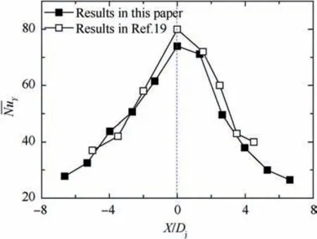
4.3. Heat transfer distributions in span-wise direction

4.4. Effect of impingement hole diameter on heat transfer distributions
4.5. Surface averaged heat transfer performance


5. Conclusions
