A trajectory planning method on error compensation of residual height for aero-engine blades of robotic belt grinding
Chong LV, Lai ZOU, Yun HUANG, Xifan LIU, Zhaorui LI, Mingwang GONG,Heng LI
State Key Laboratory of Mechanical Transmission, Chongqing University, Chongqing 400044, China
KEYWORDS Aero-engine blade;Double-vector controlling;Interpolation algorithm;Residual height error;Robotic grinding
Abstract While the traditional trajectory planning methods are used in robotic belt grinding of blades with an uneven machining allowance distribution, it is hard to obtain the preferable profile accuracy and surface quality to meet the high-performance requirements of aero-engine. To solve this problem,a novel trajectory planning method is proposed in this paper by considering the developed interpolation algorithm and the machining allowance threshold. The residual height error obtained from grinding experiments of titanium alloy sample was compensated to modify the calculation model of row spacing, and a new geometric algorithm was presented to dynamically calculate the cutter contact points based on this revised calculation model and the dichotomy method. Subsequently, the off-line machining program is generated based on a double-vector controlling method to obtain an optimal contact posture. On this basis, three sets of robotic grinding tests of titanium alloy blades were conducted to investigate the advantages of the proposed method.The comparative experimental results revealed that the presented algorithm had improved the surface profile accuracy of blade by 34.2% and 55.1%, respectively. Moreover, the average machined surface roughness was achieved to 0.3 μm and the machining efficiency was obviously promoted.It is concluded that this research work is beneficial to comprehensively improve the machined quality of blades in robotic belt grinding.
1. Introduction
As an important energy conversion part of the aero-engine,blade has been developing in the directions of multispecification, high precision large space distortion and materials diversification.Traditionally,the manual grinding and polishing method is difficult to ensure the surface profile accuracy and machined quality consistency.The titanium alloys widely used in this filed are considered as the typical hard-to-machine materials. In this regard, the kinds of research progress on grinding and polishing of these materials of difficult machining are presented.In especial, a novel green chemical mechanical polishing (CMP) has been developed for the titanium alloys, nickel alloys and other materials, to effectively overcome the issues of high cost,great pollution and long processing time on treatment of corrosive slurries.In addition, a novel approach of single grain cutting is performed at nanoscale depth of cut, and the speeds used in nanoscale depth of cut are three to six orders magnitude higher than those used in conventional nanoscratching.The method opens a new pathway to investigate the fundamental mechanisms of abrasive machining for achieving the high-performance surfaces,consisting of grinding and polishing.The above literatures provide a basic guidance for machining of those difficult-tomachine materials, and also indicate that it is very important to explore suitable and novel precision machining methods for complex curved parts made of titanium alloy materials.
Robotic abrasive belt grinding has gradually become a semi-finishing and finishing method for complex surface blades as the preferable flexibility and versatility.It is noteworthy that the trajectory planning technique of robotic grinding directly determines the machining accuracy and efficiency,which will affect the service performance of aero-engine.The trajectory planning method proposed in this paper is different from other trajectory methods applied to manipulators or other vehicles in design principle. It will be mainly used in the precision machining field. Furthermore, the key foundations of trajectory planning are to reasonably design the trajectory interpolation algorithm,the material removal model on the trajectory, real-time detect the machining allowance and control the robotic posture. Many researchers have done a lot of research on the trajectory interpolation algorithm and material removal model.
Thus, Ma et al.proposed a modified grinding path by using bicubic B-spline interpolation. The key contact points were refined based on the surface curvature. Huang et al.proposed an adaptive wide line trajectory planning algorithm based on iso-parametric method. The processing interference was effectively avoided by considering the relationship between the contact wheel width and the surface curvature.Shi et al.adopted the iso-parametric method to polish the blade, which also considered the machining bandwidth for the row spacing calculation. He et al.combined the global geometric iteration method with the local corner transition scheme to generate a smooth path with G2 continuous, data tolerance and chord tolerance constrained. Chaves-Jacob et al.used a five-degree polynomial interpolation to generate an optimized toolpath for 5-axis machines and industrial robots, which improved both the tool wear and surface covering during polishing process. Zhao et al.took the parameter u as the function of time t to discretize the curve and considered the dwell time of each trajectory.Then,the optimized trajectory planning method had an order of magnitude improvement in interpolation and runtime, compared to the linear interpolation method. Sun et al.proposed a unified method of generating CNC tool path based on multiple vector fields for compound NURBS surfaces.Yang et al.generated the grinding path for the error region of blades by the isoparameter method, which could improve the machining efficiency and achieve the entire error region machining completely. Liu et al.proposed a time-optimal and jerkcontinuous trajectory planning method by combining the spline interpolating in Cartesian space and B-spline interpolating in joint space, and improved the practical performance of tracking control for robot manipulators.
Besides, the surface profile accuracy and machined quality of blade is greatly affected by the material removal on the trajectory. Chen et al.developed a novel smart end effector to maintain an expected force value on each tool path, and further to improve the ability of accurate removal as well as the dynamic stability of robotic belt polishing system. Wu et al.established a model to predict the material removal rate on each path, in consideration of the robot velocity and contact force between the workpiece and the contact wheel. Song et al.investigated an off-line trajectory planning for the precise controlling of material removal based on an adaptive modeling method. Wan et al.proposed a new regionadaptive path planning method for robotic precision polishing on optical parts. The tool path was generated adaptively by considering the specific form error and the varying of dwell time. Ren et al.proposed a local process model to estimate the material removal rate, and calculated the minimum number of contact points on each path through the discretization error w and the distance l between two adjacent contact points.Nagata et al.generated the basic tool path by mainprocessor of the CAM, and controlled the polishing force by the impedance model in robotic sanding system. Lv et al.considered the elastic deformation at contact wheelworkpiece interface, and proposed an improved constant chord-height error method for robotic belt grinding of blade leading edge (LE) and trailing edge (TE).
The above research methods mainly focus on the interpolation algorithm of the iso-parametric method and the isoscallop method to calculate the cutter contact (CC) points,or achieve a more accurate material removal by optimizing the material removal model. Although they can realize the machining accuracy requirement of blades, the residual height error and the uneven machining allowance are not considered in these methods, which is hard to achieve precision grinding of complex blades with the robot, especially at LE and TE.
To address this issue,a novel path planning method is proposed in Section 2.With this method,the grinding path can be generated based on the residual height error compensation,the proposed geometric algorithm, and the machining allowance threshold. Therefore, the contributions of this paper are as follows.
1) A developed trajectory planning method is proposed to improve the machined surface profile accuracy of blades.
2) The residual height error Δh obtained from grinding experiments of titanium alloy sample is compensated to modify the calculation model of row spacing.
3) A new geometric algorithm is designed to plan the next path, which can dynamically calculate CC points based on the curvature change of blades.
4) The machining allowance threshold s is set to decide whether CC points are used for the rough or fine grinding.
5) A double-vector controlling method is designed to obtain an optimal contact posture between the contact wheel and the blade.
6) The robotic grinding tests of titanium alloy blades with different trajectory planning methods are conducted to validate the effectiveness of this work.
2. Trajectory planning
Fig. 1(a) shows the three-dimensional model of a titanium alloy compressor blade. The trajectory planning procedure of robotic belt grinding blades, as shown in Fig. 1(b), is mainly divided into two parts.Obtaining the CC points by discretizing the machining area based on the algorithms of the row spacing and the step length. Determining the contact posture between the contact wheel and the blade at the corresponding machining point, and generating the robotic off-line machining program by post-processing algorithm involving the CC points.
The main principles of three trajectory planning strategies(the iso-parametric method, the iso-scallop method and the developed method) are described as below. These three methods are implemented based on the self-developed software.
2.1. Iso-parametric method
Taking u-direction as an example, the iso-parametric method evenly discretizes the machining area [v, v] in the row spacing direction by the set number of machining paths.This method discretizes the machining area [0,1] in the step length direction by the set constant chord error δ,or discretizes evenly the machining area[u,u]by the set number of CC points on each path, as shown in Fig. 2.
The iso-parametric method has been widely applied in grinding and polishing the simple surface due to its convenient and high efficiency calculation. However, the number of machining points and paths in this method are mostly set by the experience, and this method does not take the curvature change at each machining point into consideration when discretizing the complex surface of blades.
2.2. Iso-scallop method
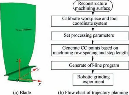
Fig. 1 Schematic diagram of blade trajectory planning.
Although the discretization principle of each path of the isoscallop method is consistent with that of the iso-parametric method,they adopt different methods to calculate the machining row spacing.Noting that the machining row spacing calculation principle of the iso-scallop method is to ensure a constant residual height between the corresponding CC points of two adjacent paths. For the convex surface (CV), as shown in Fig. 3(a), the machining row spacing Lof the CC point P(u), also the current machining point in Path(i-1), can be calculated by the Pythagorean theorem according to its radius of curvature and contact wheel.In this way, the corresponding machining point Pʹ(u) of the next path can be obtained.

where R is the curvature radius of P(u),Ris the contact wheel radius, and h is the residual height.
The row spacing Lcalculation principle of the concave surface (CC) as shown in Fig. 3(b) is the same as that of the CV surface, which is obtained as below.

There is an error Δh between the set residual height value and the actual residual height value h due to the characteristics of elastic contact in belt grinding. The machining area is hard to be controlled because the working points can easily beyond or not reach the surface boundary in the actual grinding process. In addition, if the machining allowance threshold is not taken into account, only equal allowance material remove at each machining point can be realized. For these reasons, this method is difficult to achieve a high accuracy robotic belt grinding on blades.
2.3. The developed trajectory planning method
The main principle of the developed trajectory planning method proposed in this paper is described as follows. Compensating the residual height error to revise (1) and (2). Using the geometric algorithm to calculate the next path until the path reaches the boundary of the machining area. Screening the obtained CC points by the varying of machining allowance threshold to select implementing rough or fine grinding.
In the robot belt grinding system, the normal contact pressure between the contact wheel and the blade makes the rubber contact wheel elastically deformed,as shown in Fig.4.Besides,the material removal is greatly influenced by the workpiece feed rate v,the abrasive belt grinding speed vand the contact wheel normal displacement u.
The trajectory planning method considers the material removal of each path,while the residual height error is not compensated.To determine the relationship between the theoretical residual height hand the actual residual height h, the orthogonal grinding experiments of titanium alloy plate by robot are carried out to revise the row spacing calculation model (1) and (2).
Fig. 5(a) shows the calculation diagram between the theoretical residual height hand the machining row spacing L between two adjacent paths. From which, the following equation can be obtained.

The machining row spacing L can be calculated as below.
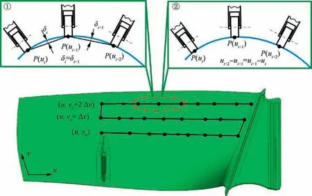
Fig. 2 Iso-parametric method.
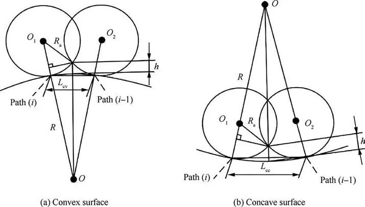
Fig. 3 Schematic diagram of calculating machining row spacing.
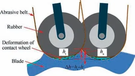
Fig. 4 Schematic diagram of residual height error generation.

According to the previous research foundations of our group,the main processing parameters of orthogonal grinding tests are shown in Table 1.Fig.5(b)shows the robotic belt grinding process of the titanium alloy sample. While the machining row spacings of all grinding tests are set to 1 mm,the theoretical residual height his calculated to be 7.35 μm by Eq. (4). The actual residual heights hof the sample was measured by the Retec MFT-5000 white light interferometer,and the experimental results were shown in Table 2. It can be seen that the actual residual heights hof two adjacent paths are different from present combinations of the processing parameters. Moreover, the difference between the minimum residual height hand the theoretical residual height his more than three times, so compensation of the residual height error is necessary.
It can be seen that the residual height hin Fig. 5(d) is larger than that as shown in Fig.5(c).The reason is that the smaller feed rate vresults in longer dwell time between the blade and the contact wheel, and the larger of the grinding speed vresults in higher material removal amount.
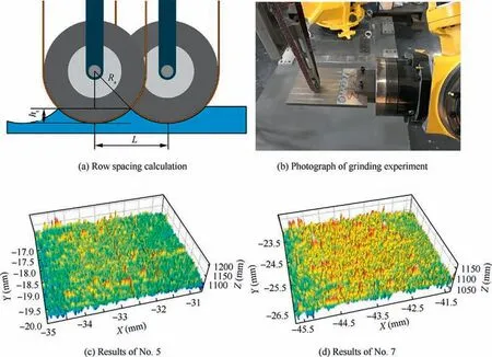
Fig. 5 Compensation of residual height error Δh.
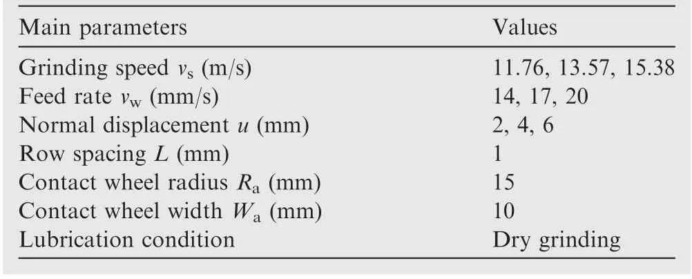
Table 1 Main processing parameters of orthogonal grinding tests.
According to the results of Table 2, the relationship between the actual residual height hand grinding process parameters is obtained by the multiple linear regression method. By minimizing the residual error of this regressionmodel, the least square method can be used to calculate the parameters in Eq. (5). The residual error and confidence of the linear regression analysis can be calculated by the mathematical statistics. The regression analysis results show that the Eq. (5) can effectively predict the actual residual height hin the grinding process. There will be a difference between a plane and a surface caused by the different contact states.The curvature of the blade profile varies greatly, and the variation law is not consistent with the different sections. Therefore, the current research work is based on the plane grinding tests to obtain the basic law. Once the grinding regions are divided, the maximum and minimum curvature radius of grinding regions can be calculated. The correction factor is introduced to adjust the residual height error according to the range of curvature radius change based on the previous research experience. Currently, the correction factor is set to be greater than 1 while grinding CV surface and less than 1 while grinding CC surface, which is achieved by setting a value varied within a certain range in the self-developed CAM software.
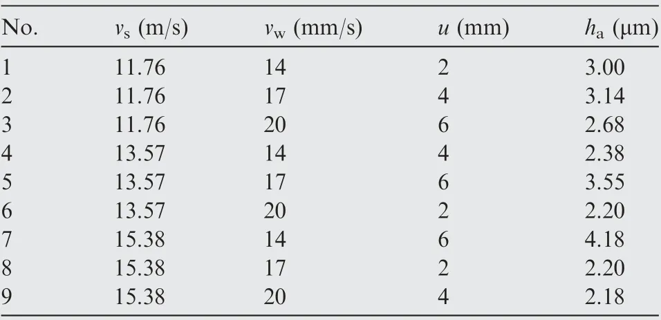
Table 2 Results of orthogonal experiments.

The higher order term of the residual height h is fully considered in Eq. (1)-Eq. (2). Fig. 4 shows the relationship between the actual residual height hand the theoretical residual height h. Then, the residual height error Δh can be calculated by the difference between them. Besides, the equivalent radius of the contact wheel can be regarded as the sum of the radius of the contact wheel and the thickness of the abrasive belt.Therefore,considering the above factors,Eq.(1)-Eq.(2) are modified as follows in full consideration of the thickness d of the abrasive belt and the residual height error Δh.
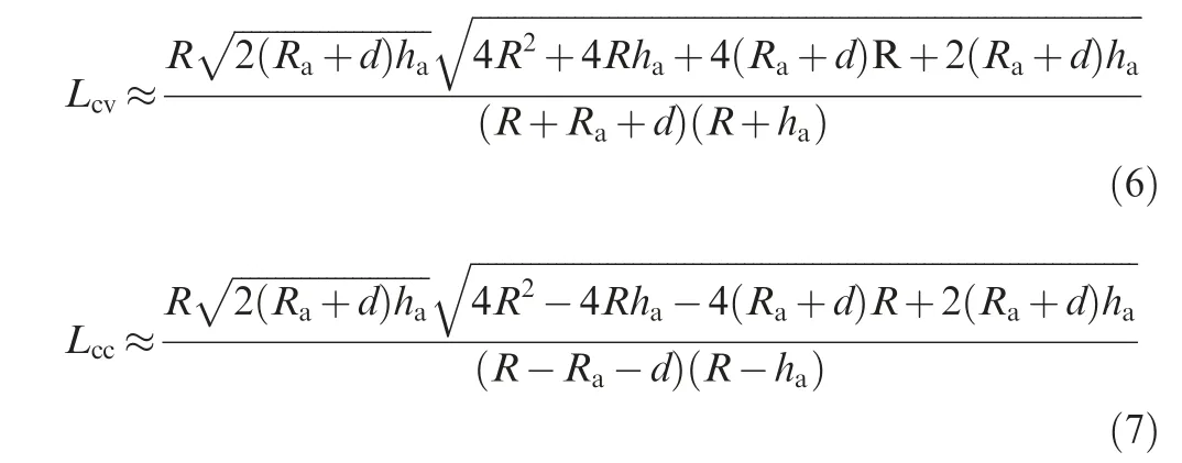
Subsequently,a geometric algorithm is designed for discrete machining regions according to the Eq. (5)-Eq. (7). The main principle of the geometric algorithm is making a circle with diameter Lin the n×du direction based on the current machining point A of Path(i) and its row spacing L. Then the intersection point B between the circle and the blade surface is regarded as the corresponding machining point of the next Path(i + 1), as shown in Fig. 6. In consideration of controlling the posture of the contact wheel in the robotic belt grinding, the direction of the circle needs to be specified.Besides, this direction can be calculated by the cross product between the normal direction n and the tangent direction du based on the double-vector controlling method.
It is easy to cause an over cutting for the large difference of curvature radius R between A and B. That is attributed to the calculated Lwill increase if R>R, as shown in Fig. 7(a).Therefore, the curvature radius Ris introduced to calculate the current row spacing L again.The curvature radius R is calculated by the maximum curvature kof the current machining point. The purpose of choosing the maximum curvature radius is to reduce the possibility of overcutting as much as possible. This is because the selection of the large curvature radius can make the row spacing Lsmaller according to the Eq. (6)-Eq. (7), and the smaller Lcan make the CC points denser.

where Rand Rare the curvature radius of point A and B,respectively. P(u) is the parametric representation of the current machining point A.
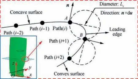
Fig. 6 Geometric method of calculating the next path.
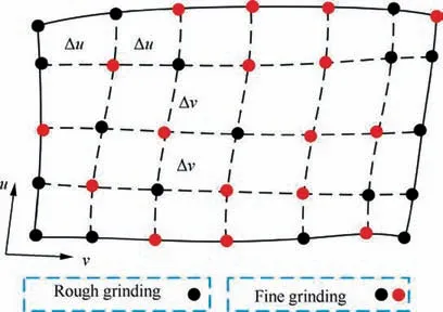
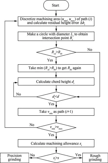
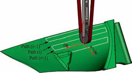
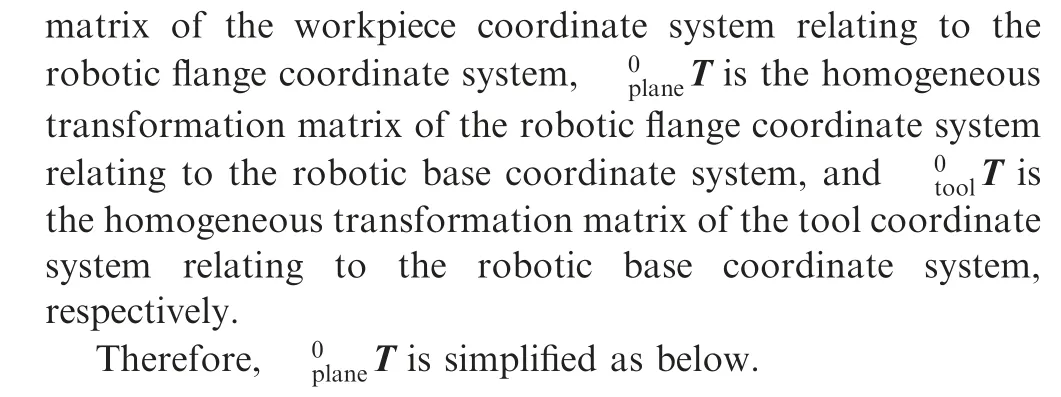
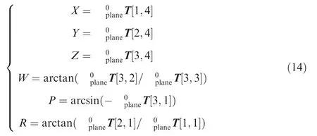
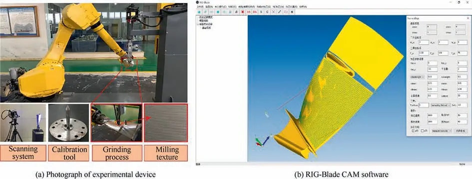
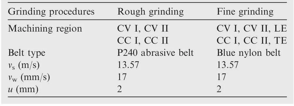
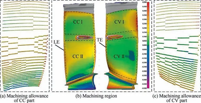
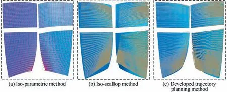
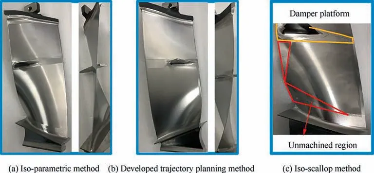
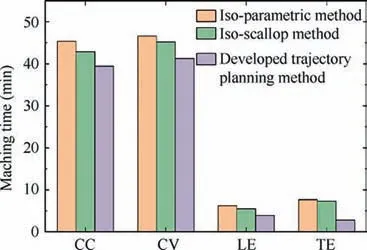
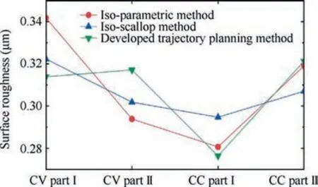
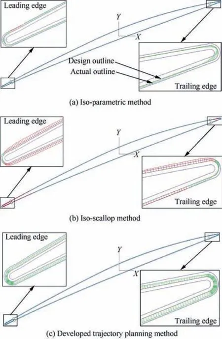
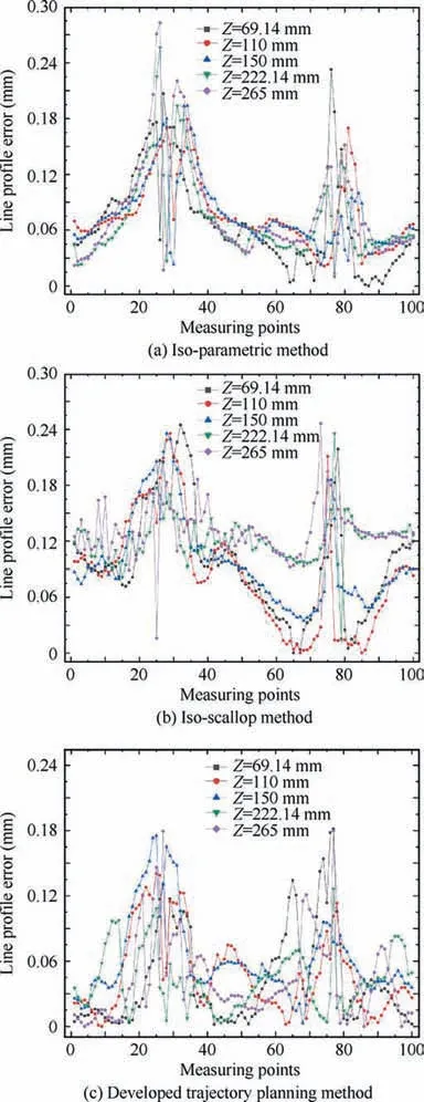
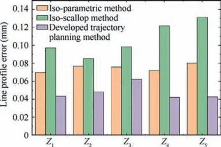
After getting point B again, dcan be calculated, which is the distance from the midpoint C of chord AB to the blade surface.If dwas less than the set chord error d,the next machining point of path(i) should be continue calculated. Otherwise,the midpoint D of the line segment AC shall be taken to calculate dʹ,which is the distance from D to the blade surface.This step will be finished by comparing dʹwith the set chord error d until dʹ vʹis used as the parameter of the second path after obtaining all CC points of the second machining path. where n is the number of the CC points on the second path,vis the parameter value of the machining point in v direction. Then, the second path is discretized according to the first path discretization principle, and continue to find the next path based on the geometric method until v’ >v(vis the machining boundary parameter). At this point, the whole machining area has been discretized and the CC points can be generated. Although this methodoptimizes the trajectory interpolation algorithm, it does not consider the distribution of the machining allowance.Therefore,this paper presents a method to screen all the CC points for rough grinding and fine grinding.Firstly,the actual 3D model of the blade is scanned online by the multi-functional scanning system and matched with the theoretical model through the least square method.According to the CC points generated above,a straight line is made along the normal direction n of the machining point P(u)to intersect with the actual model. The distance sof the line segment between the machining point and the intersection point is the machining allowance value of P(u). where x, y, and zare the coordinates of the machining point, and x, yand zare the coordinates of the intersection points. Subsequently, the allowance threshold value s is set. If the allowance value of a machining point is larger than the allowance threshold value, the point is saved for rough grinding. Otherwise, it is used for fine grinding, as shown in Fig. 8. The main principle of the developed trajectory planning method is shown in Fig. 9,which includes the following steps. Step 1: Taking u direction machining as an example, we select the first path v = v, and discretize the machining area[u, u] based on the constant chord error δ. Step 2:The row spacing Lis calculated by using the Eq.(5)-Eq.(7).The initial intersection point Bis calculated by making a circle with diameter L. Step 3:We select the Rʹto revise L,and then,calculate the chord error dʹuntil dʹ< d. Step 4:Using Eq.(10),the next path is calculated,then the machining area[u,u]is discretized by the constant chord error δ. Fig. 7 Optimization of row spacing calculation. Fig. 8 Distribution diagram of CC points. Step 5: Steps (2) - (4) are repeated until vʹ>v. The coordinates, tangent and normal vectors of all CC points can be stored in the data structure. Step 6: The allowance threshold value s is set to screen all CC points to determine whether they are used for rough or fine grinding. CC points cannot be directly used for grinding. It has to generate the machining program according to the corresponding post-processing algorithm.Robotic belt grinding needs to control the axial direction of the tool and the direction of the supporting axis, namely the double-vector controlling method. The supporting direction of the contact wheel can control the contact force direction conveniently when it is along the normal direction n of the blade at the working point. Besides,the axis direction of the contact wheel can make a good fitting state between the contact wheel and the blade when it is along the tangent direction of the working point,as shown in Fig.10.The coordinated control of the supporting direction and the axis direction of the contact wheel is used to achieve the goal of grinding blades by the robot. Eq. (12) is obtained according to the principle of robot kinematics. Fig. 9 Flow chart of the developed trajectory planning method. Fig. 10 Schematic diagram of controlling the robot posture. The alumina hollow-sphere ceramic abrasive belt is used in grinding experiments as the advantages of high wear resistance and high removal efficiency. The hollow sphere abrasive belt(grain size is about 60 μm) is used for rough grinding to remove the milling texture,and then the blue nylon belt is used for fine grinding to improve the machined surface roughness.The specific grinding process scheme is shown in Table 3. Then, the position and attitude of the tool coordinate system can be obtained, as expressed in Eq. (14). where X, Y, and Z are the coordinate values of the robotic flange tool center point in the robot base coordinate system.W, P, and R are the angle values of the robotic flange coordinate system rotating around the x, y, and z axes of the robot base coordinate system, respectively. Data (X, Y, Z, W, P, R) of all CC points can be combined to generate the robot off-line program by the code format of FANUC robot. Fig. 11(a) shows the robotic belt adaptive grinding system,which is consisted of a FANUC M-710iC/50 robot, a HEXAGON smartSCAN blue light scanning system, a calibration tool, a contact wheel with active and passive floating compensation function, and titanium alloy blades. The titanium alloy blade, which is installed at the end of the robot flange plate, has obvious milled marks on the surface before grinding. The blade is composed of the CV surface, the CC surface, the LE, the TE and the damper platform. Fig. 11(b) shows the developed the RIG-Blade CAM software through C++ programming language based on the 3D modeling engine and the Microsoft Foundation Classes. The functions of this self-developed RIG-Blade include importing STL, IGES and other commonly used 3D models, fitting blade profiles by the measured point data, generating the grinding programs for commonly used industrial robots,and simulating the robotic grinding processes without interference. Fig. 12(b) shows six grinding regions divided by the consideration of the allowance distribution and structural feature of the blade. The allowances of the CC part and CV part are shown in Fig.12(a)and(c).The main parameters are the residual height h, the allowance threshold s and the chord error d.The residual height h is set according to the machining accuracy requirement of the blade, while the chord error d is set according to the surface roughness. The allowance threshold s is set according to the average value of the machining allowance distribution in the grinding area.Taking the CV part I as an example, its allowance distribution is about 0.0-0.3 mm.Therefore, the allowance threshold value s is set to 0.2 mm for rough grinding and 0 mm for fine grinding. Setting all the grinding parameters on the self-developed software,and then the tool paths based on the three trajectory planning methods can be generated as shown in Fig.13.It can be seen that the machining paths and points of the isoparametric method are relatively uniform. This is because the method does not consider the changes in blade curvature.The machining paths and points of the iso-scallop method and the proposed method can be calculated dynamically,while the iso-scallop method cannot reach the machining boundary. Fig. 14 presents the blades obtained by robotic belt grinding with the iso-parametric method, the iso-scallop method and the presented trajectory planning method. After fine grinding,the surfaces of the three blades are quite smooth. The blades grinded by the iso-parametric method and the presented method have almost the same appearance, as shown in Fig. 14(a) and (b). However, the iso-scallop method cannot control the machining region very well.Taking the CV surface as an example, as shown in Fig. 14(c), the actual machining region does not reach the desired machining limit. Although the appearance of the three blades is similar, the machining efficiency, surface roughness and profile accuracy may differ greatly. Therefore, the three methods have been compared and analyzed from these aspects. The damper platform of the blade is not considered to be machined with these three methods to reduce the time of grinding test. Fig. 11 Robotic adaptive machining platform. Table 3 Process scheme. 4.3.1. Machining efficiency Fig. 15 shows the comparison of machining efficiency at each machining region of blade by using different trajectory planning methods. It can be seen that the machining efficiency of the developed method is highest for all the machining regions,while the iso-parametric method is the lowest. Moreover, the total machining times of blade are 105.8 min, 100.8 min and 87.5 min, respectively. The tool path generated by the isoparametric method has not considered the curvature change of blades. Besides, its main parameters are mainly set according to human experience. Therefore, to meet the requirements of grinding accuracy, it is necessary to set enough paths and CC points, which leads to low machining efficiency. The isoscallop method and the developed interpolation algorithm can dynamically generate the tool path based on the curvature change of blades.As a result,the two methods generate a fewer machining paths and CC points and lead to higher machining efficiency. In addition, the developed interpolation algorithm could generate dense CC points at the place with large curvature change and generate sparse CC points at the place with small curvature change. Also, all the CC points screened by the set allowance threshold are beneficial to improve the machining efficiency. 4.3.2. Surface roughness Fig. 12 Blade machining allowance detection. Fig. 13 Tool paths. Fig. 14 Photographs of grinding results. Fig. 15 Machining time of each region. The machined surface roughness Rof each part perpendicular to the feed direction is measured by the Taylor Hobson FTS intra type roughness meter. According to the four regions of the blade shown in Fig. 12 (CV part I, CV part II, CC part I,CC part II),each region is sampled five times for calculating its average surface roughness Rto reduce the measurement error. The measured results in Fig. 16 indicate that there is no significant difference after fine grinding by using these three methods. The average roughness values Rof three blades are all about 0.3 μm.It can be deduced that the trajectory planning method has little influence on the surface roughness. The reason is that the trajectory algorithm has little effect on the roughness of the blade when it is being polished with the blue nylon belt. Fig. 16 The surface roughness of each processing region. 4.3.3. Profile accuracy The profile accuracy of blades were measured using the Hexagon global series three coordinate-measuring machines. The measuring and evaluating results of the same section(Z = 69.14 mm) with the tolerance zones set as 130 μm are shown in Fig. 17. Fig.17(a)shows that the blade grinded with iso-parametric method can meet the tolerance zone at CC and CV.However,the machining accuracy of LE and TE is hard to be controlled as this method lacks considering the great curvature change in LE and TE, resulting in less CC points. Besides, this method does not consider the machining allowance distribution of each parts and the elastic deformation of the contact wheel, so it is difficult to ensure the machining accuracy requirements of blades, especially at LE and TE. The machining accuracy of blade grinded with the iso-scallop method is the worst because this method does not compensate the residual height error Δh and cannot control the machining area well. There are some places, especially at LE and TE, cannot even be grinded. In addition,the machining allowance distribution is also not considered.Fig.17(c)shows that the blade grinded with the developed method can meet the requirements of machining accuracy. This is because that the blade can be grinded to a uniform machining allowance distribution according to the allowance threshold.In addition,the dense CC points are generated at the places with large curvature changes, such as the LE and TE,so that the grinding material removal at this place is large.Then,the blade can be grinded into the tolerance zone. For five measurement sections of blades with Z = 69.14 mm/110 mm/150 mm/222.14 mm/265 mm, the deviation values of 100 measuring points are selected from each section for the line profile error calculation. Fig. 18 shows that the blades deviation values of the iso-parametric method and the iso-scallop method are not uniform, especially at the LE and TE. The deviation values of blade grinded by the developed trajectory planning method are uniform. By comparing the line profile error of the same section, as shown in Fig. 19, the line profile error of the blade grinded by the developed trajectory planning method is greatly improved, and the line profile error is relatively stable. Fig. 17 Comparison of blade grinding. Fig. 18 Line profile error of blades. Compared with the traditional iso-parametric method and the iso-scallop method, the computational complexity of the proposed method is higher as considering the compensation of residual height error,uneven machining allowance distribution and the curvature change of blade.Although the response time of the proposed method is longer, the machined surface profile accuracy and machining efficiency of the blade obtained by using the proposed control scheme have been improved obviously. The surface profile accuracy of the blades of the three trajectory planning methods are calculated by the average of the five section errors to be 74 μm, 107 μm and 48 μm, separately. The surface profile accuracy of the blade grinded by the developed trajectory planning method is 34.2% and 55.1% higher than the other two methods, respectively. That is attributed to the developed interpolation algorithm compensates the residual height error Δh to modify the calculation model of machining row spacing, so as to generate dense CC points at the positions with large curvature changes and sparse CC points at the positions of small curvature changes. Furthermore, this method could screen the CC points according to the machining allowance distribution of the blade and grind the blade to a uniform distribution of the deviation value. Thus, under the condition of meeting the machining accuracy the developed trajectory planning method is the preferred choice. Fig. 19 Line profile errors of Z1-Z5. This work presents a trajectory planning method based on the error compensation of residual height to generate the tool path of robotic abrasive belt grinding. The comparative grinding experiments of titanium alloy blades are conducted to verify the validity. The main conclusions are summarized as follows. (1) A developed interpolation algorithm is proposed to solve the problem of the existing methods which considering the contact deformation in robotic belt grinding.The residual height error Δh is compensated in the proposed algorithm based on the experimental results of grinding titanium alloy sample. Then, the calculation formula of row spacing L is revised. (2) The setting of the allowance threshold value is applied in this trajectory planning method to both homogenize the machining allowance of the blade and reduce the number of CC points. The experimental results reveal that the machining efficiency of the presented method is obviously improved. The machining time is 17.3% lower than that of the iso-parametric method and 13.2%lower than that of the iso-scallop method. (3) The generation of dense and sparse CC points on the blade surface with varying curvature is achieved by the developed interpolation algorithm.On this base,the surface profile accuracy of the blade is obtained to be 48 μm, which has been improved by about 34.2% and 55.1%, respectively, in comparison with that of the former methods.Additionally,the machined surface roughness obtained by these three methods is close to 0.3 μm. Our follow-up research will mainly focus on reducing the response time of the proposed method. In addition, it would be also worthwhile to study the effect of the parameter variations (e.g., the grain size) and system uncertainties on the machining efficiency and accuracy of blades. The authors declare that they have no known competing financial interests or personal relationships that could have appeared to influence the work reported in this paper. s This study was supported by the National Natural Science Foundation of China(No.52075059)and the Natural Science Foundation of Chongqing (No. cstc2020jcyj-msxmX0266).


3. Post-processing algorithm of CC points


4. Robotic belt grinding experiments
4.1. Experimental preparation
4.2. Trajectory generation
4.3. Experiment and results analysis
5. Conclusions
