Design and experiment of concentrated flexibility-based variable camber morphing wing
Yuzhu LI, Wenjie GE,*, Jin ZHOU, Yonghong ZHANG, Dongli ZHAO,Zhuo WANG, Dinio DONG
a School of Mechanical Engineering, Northwestern Polytechnical University, Xi’an 710072, China
b School of Aeronautic Science and Engineering, Beihang University, Beijing 100083, China
KEYWORDS Aircraft;Concentrated flexure hinge;Leading-edge;Morphing wing;Pseudo-rigid-body model
Abstract The morphing wing has a significant positive effect on the aerodynamic performance of the aircraft.This paper describes a leading-edge of variable camber wing with concentrated flexibility based on the geared five-bar mechanism. The driving points of morphing skin formed by the glass fibre composite sheet were optimized to make the skin deformation smooth. A geared fivebar kinematic mechanism rigidly connected to the skin was proposed to drive the leading-edge deformation. Besides, a new kind of concentrated flexure hinge was designed using the pseudorigid-body method and applied to the joint between the rigid mechanism and the skin. Finally,the leading-edge prototypes with traditional hinges and flexure hinges were produced, respectively.The feasibility of the concentrated flexibility leading-edge was verified through the comparative experiments of ground deformation.Simultaneously,aerodynamic analysis was carried out to compare the concentrated flexure leading-edge wing with the original airfoil.
1. Introduction
The current fixed-wing aircraft’s aerodynamic performance can be improved by the deformation of the flaps, slats, and spoilers. However, this deformation method will create a gap between the control surface and the wing box skin, making the airfoil surface discontinuous and generate parasitic resistance and noise.Through the observation of bird flight,the researchers proposed the morphing wing concept.The morphing wing can adjust the airfoil smoothly and continuously according to flight conditions or other requirements,which can ameliorate the lift-to-drag ratio, energy consumption, and other aircraft performance.Simultaneously, morphing wing enabling aircraft designers to concern with multiple flight conditions, get rid of the trouble caused by the single aerodynamic shape of the wing.
The deformation method of the morphing wing is approximately divided into three types: out-of-plane deformation(spanwise bending morphing,twisting morphing,and foldable morphing), in-plane deformation (variable span,chord length,and sweep angle) and airfoil deformation (variable camber,variable thickness).Among these methods, the variable camber wing can obtain relatively large aerodynamic benefits with a small change in wing planform shape.
For traditional skins, its main function is to bear the load and maintain the aircraft’s aerodynamic shape. However, the morphing wing’s skin needs to meet the load-bearing requirements and achieve the deformation in the functional direction.At present, researchers mainly use new structures and materials to study skins.The new structure can ameliorate the in-plane and the out-of-plane stiffness of the skin to a certain extent; for example, the skin is designed with corrugated and honeycomb structures.Apart from the integrated structures, combination structures are also used in the design of morphing skin. Philen et al. implanted composite tubes into a flexible matrix and adjusted the skin’s stiffness and shape by changing the pressure in each tube.You et al. proposed a morphing skin by a gripper pin structure to decrease the actuation energy.Nevertheless, the skin with the new structure could be limited in the materials, carrying capacity and stress concentration.Besides,CRG Corporation in the United States has proposed a variety of morphing skins based on memory alloys and polymers with honeycomb structure,but the cost, the reliability, and the complexity of this design limited potential at the current state.Therefore,it is challenging to design a flexible skin with the performance that deformation smoothly and the excellent ability of aerodynamic shape maintenance.
In the early stage, the variable camber wings were mainly driven by rigid mechanisms,such as the mission adaptive wing technology research carried out by the joint of United States Air Force/NASA/Boeing,the variable camber trailing edge that driven by multi-finger mechanism investigated by the German Aerospace Center,and the leading-edge based on the linkage mechanism designed by Dornier.Even so,the rigid mechanism’s research and development are limited by the weight and wear problems,especially for the small aircraft with narrow design space. Due to the advantages of the simple structure, frictionless, and no need for lubrication, the flexible mechanism has also been used to design morphing wings in recent years. For example, FlexSys Inc. used a compliant mechanism designed by the continuum topology optimization method to achieve the wing’s camber deformation.By using the same mechanism and strategy,the leading and trailing edges of variable camber compliant wing are researched by AFRL.However, the deformation and load-bearing performance are a trade-off for the flexible mechanism,which limited the flexible mechanism to small UAVs’ research field for a long time. Additionally, as a new actuation, the smart materials have been integrated into the morphing wing.Nonetheless, there are technical problems such as small driving force and low response speed, so the smart material application is still in the stage of exploration and research.Considering the characteristics of rigid and flexible mechanisms, combining the two mechanisms’ advantages to designing the drive mechanism is a better solution.
Compared with traditional four-bar or six-bar mechanisms,the geared five-bar mechanism has two advantages:the diverse movements and a simple control strategy.Also,its motion characteristics can be adjusted directly by changing the gear ratio.Therefore,from the perspective of reducing the drive system’s complexity and improving the shape retention and smooth deformation performance of the wing, we designed a leading-edge driven by the geared five-bar mechanism. In this paper, the morphing skin fabricated with the glass fibre composite sheet can be bent into the target airfoil under the driving point, making the leading-edge airfoil meet the curvature changing during deformation. Based on the leading-edge design space and the skin’s driving position before and after deformation, the rigid geared five-bar mechanism’s kinematic model is established. Besides, due to the flexure hinge without friction and design parameters are fewer than continuum structures, this paper introduces the symmetrical spring flexure hinge between the skin and the drive mechanism, which realizes the traditional hinge’s flexible design. Finally, the experimental prototypes with traditional hinges and concentrated flexure hinges are produced respectively, and the feasibility of the concentrated flexibility leading-edge is verified through the comparative experiments of ground deformation.
2. Design of the skin and kinematic mechanism
The airfoil curves before and after deformation are shown in Fig. 1. The span length and the chord length of the deformation part in the leading-edge are 3000 mm and 410 mm,respectively. A set of kinematic mechanisms are arranged every 500 mm. The bending angle is defined as the angle between the wing spar’s midpoint and the maximum skin curvature point before and after the deformation. This section is mainly to design the skin and the kinematic mechanism connected with the skin. The process is shown in Fig. 2.
2.1. Skin design
The leading-edge skin is crimped into an original airfoil by a glass fibre composite sheet(1 mm Thickness,Young’s modulus is 24 GPa),then deformed to the target state under the internal mechanism’s action. Therefore, it is necessary to consider the aerodynamic force and the prestress inside the skin simultaneously when we optimize the position of the skin’s driving point.First, according to the flight state parameters and the airfoil,the aerodynamic load can be obtained through computational fluid dynamics (CFD) simulation. Second, from the material’s constitutive equation and the principle of virtual work, the prestress and prestrain existing in the skin can be transformed into equivalent element nodal forces.However,when we calculate the skin’s internal force,bending the sheet directly into the target airfoil requires more node displacement constraints,which will make the calculation difficult to converge. To address this problem,we proposed a multi-step method to calculate the internal force of the airfoil: (1) fix the skin material to the frame and move the other end to the theoretical position, make the composite sheet naturally bend into Ω-shape;(2)apply the virtual load to the Ω-shaped skin to make the skin shape approach the original or final theoretical airfoil. The skin’s internal force can be regarded as the sum of the equivalent nodal force of the Ω-shaped skin and the reverse virtual load. The process is shown in Fig. 3. Finally, considering the internal force and the aerodynamic force as part of the constraint condition, take the aerodynamic shape maintenance ability maximization as the objective to design the driving point.The optimization process and result is shown as follows
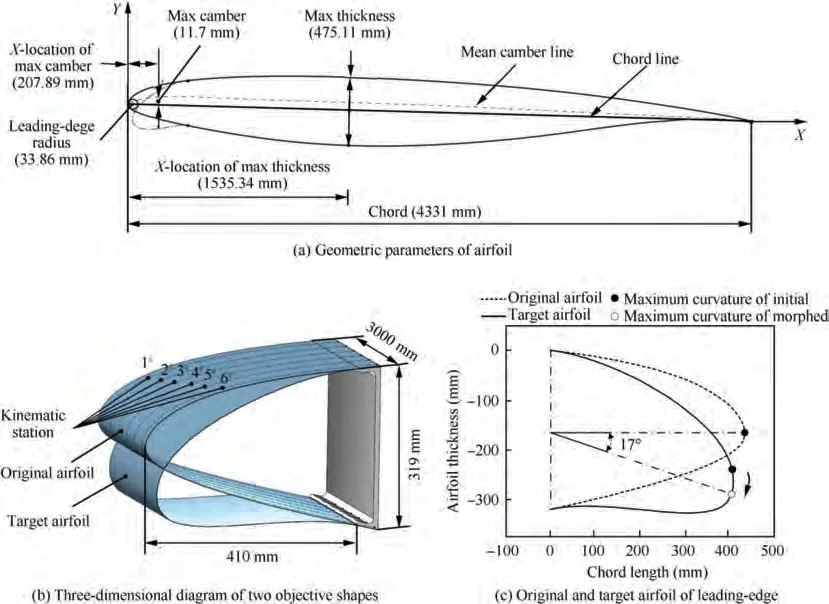
Fig. 1 Conceptual sketch of variable camber morphing wing.
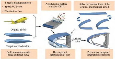
Fig. 2 Design flowchart of skin and kinematic mechanism.
(1) Optimization method
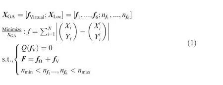
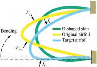
Fig. 3 Multi-step method to calculate internal force.
In order to speed up the convergence, the direction of the virtual load is defined as vertical. The objective function is defined to minimize the shape errors between the Ω-shaped skin deformed by virtual force and the original or target airfoil. The optimization problem is stated as:where,fand Xare the size and position of the virtual load respectively, N is the number of nodes on the inner side skin,[X, Y] is the node coordinates of the original/target skin and [X’, Y’] is the node coordinates of the Ω-shaped skin with load, Q is the structural equilibrium equation obtained by the response analysis of nonlinear deformation (the reasonable nodal displacements are obtained by calculating the unbalanced force in the system),fis the nodal force vector of the Ω-shaped skin, nand nare the nodal boundaries.
Due to the driving points connected to the bars in the mechanism, the mechanism’s moving components determine the number of points. When the driving point is fixed, the skin should maintain the aerodynamic shape under the load. Considering the virtual load as the constraint condition, the optimize objective is defined to minimize the strain energy of the original and target skin when the driving point is fixed.
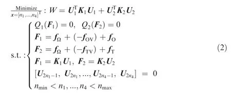
where n-nare the positions of the driving points, W is the sum of the strain energy of the skins before and after deformation,Uand Uare the node displacements of the original and target skin with load, Kand Kare the overall stiffness matrixes, Qand Qare the structural equilibrium equation,Fand Fare the external load vectors before and after deformation. f(f) and f(f) are the virtual load and aerodynamic load of the skin in the original (target) state,respectively.
(2) Analysis of optimization results
The optimization is carried out by the genetic algorithm(Genetic Algorithm and Direct Search Toolbox, GADST) in Matlab. After the optimized virtual loads applied to the Ωshaped skin, the maximum error between the initial/final state skin and the corresponding theoretical airfoil is about 6 mm,as shown in Fig.4.The ratio of the maximum error to the airfoil thickness is approximately 1.8%. At this time, the skin’s internal force can be obtained according to the virtual load’s optimization results. Following this, the driving points of the skin are optimized with the internal force and aerodynamic load. Table 1 shows the coordinates of each driving point.The maximum error between the initial/final state skin with load (including aerodynamic load) and the theoretical airfoil is 4 mm, as shown in Fig. 5. Moreover, it can be seen from Fig. 5 that the stress levels of the skin before and after deformation are lower than the yield strength (340 MPa).
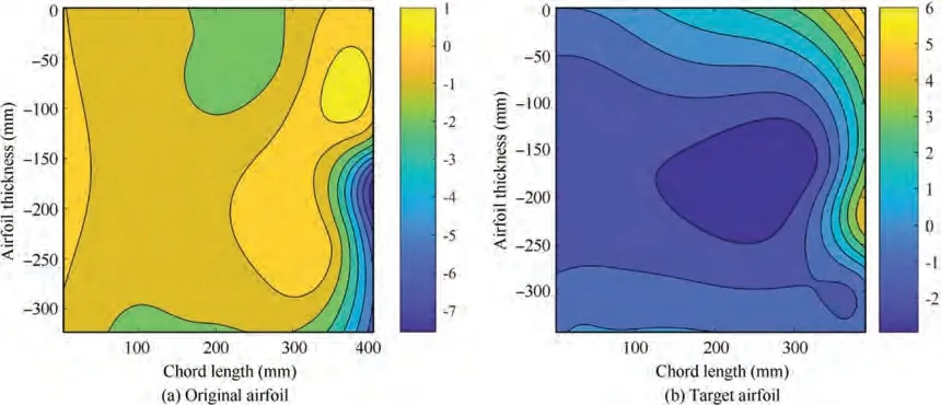
Fig. 4 Error between Ω-shaped skin under virtual loads and theoretical airfoil.

Table 1 Coordinates of driving points before and after deformation.

Fig. 5 Deformation error of skin under aerodynamic load and von Mises stress of skin before and after deformation.
2.2. Mechanism design
In the driving mechanism of the leading-edge,each driving rib is composed of a geared five-bar mechanism.The moving component in the mechanism is connected with the driving point.The relative position between the driving point and the link doesn’t change during deformation. Simultaneously, the integral stringer structure is designed at each driving point position, and it can strengthen the stiffness of the wing in the spanwise direction.
The deformation of a single driving rib is shown in Fig. 6.The solid line and the broken line represent the leading-edge’s original and target state,respectively.A-Aand B-Bare the hinge points of the kinematic mechanism, where A(A) coincident with B(B). C-Cand D-Dare the positions of the driving points on the skin before and after the deformation.θ(θ) represent the angle between the bar AA(AA) and the horizontal direction. α(α) represents the angle that the bar AA(AA)has rotated during the deformation.The side link ACA(ACA) revolve around hinge A(A), so the hinge point A(A) is located on the vertical bisector of the driving point C(C) and D(D). The abscissas of points Aand Aare xand x.According to the known coordinates of the driving points, the coordinates of points A-A, B-B, d-dand h-hcan be obtained.
The distance between the driving point and the corresponding connected bar’s two ends should remain unchanged during deformation. The parameters of the five-bar mechanism are optimized according to the principle.


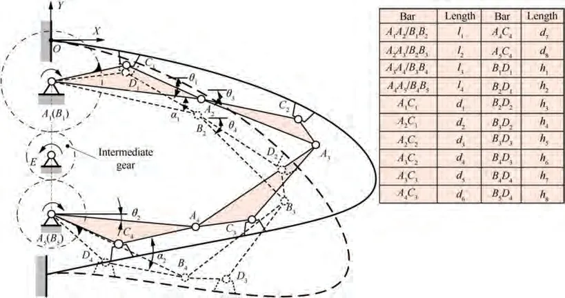
Fig. 6 Kinematic mechanism of a single driving rib.

Table 2 Optimization results of kinematic mechanism.

Table 3 Parameters of closed mechanism.
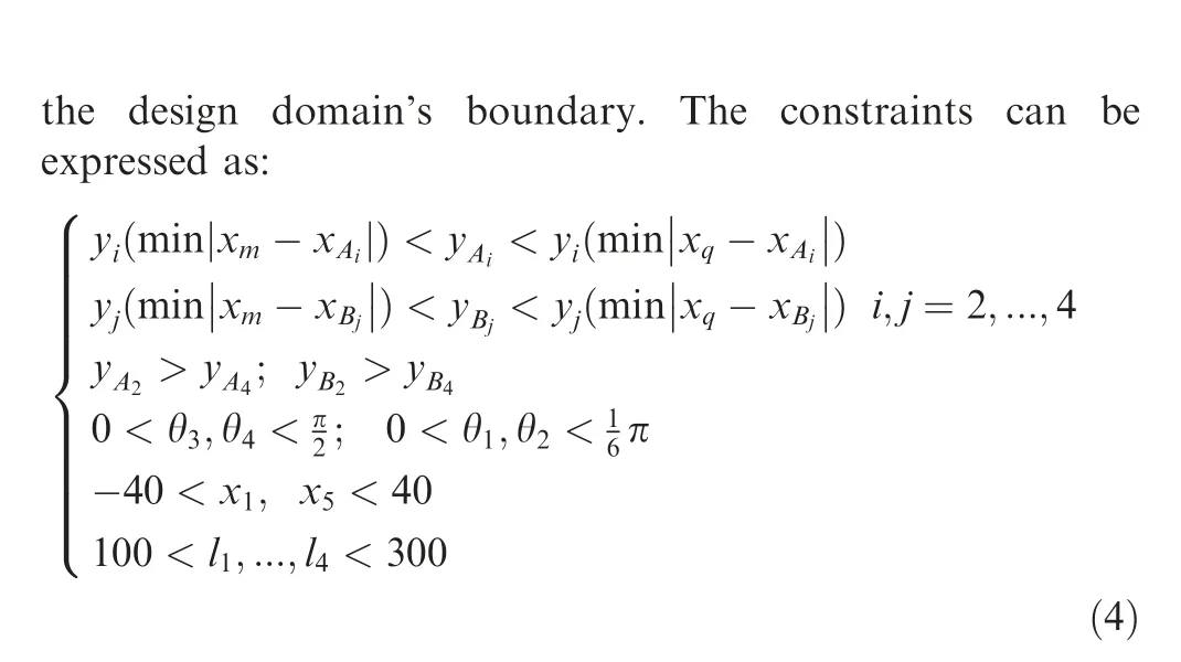
where, y(min|x-x|) and y(min|x-x|) (y(min|x-x|) and y(min|x-x|)) are the nodes’ ordinates, whose abscissas are closed to Aand Bin the upper (lower) skin. The kinematic mechanism is optimized by the genetic algorithm (GADST).The results are shown in Table 2.
In order to control the degree of freedom of the mechanism and set the rotation of the side links in the same direction, we set the side links of the five-bar mechanism as the geared-bar.The mechanism is closed by the side links meshes with the intermediate transmission gear. The diameter of the reference circle of the gear bars ACA, ACAand the intermediate gear are d, d, and d. The moments acting on the gear bars ACAand ACAare Mand M. Due to the transmission ratio and moments are constant value, the contact forces between the two gear bars and the intermediate gear decreases with increasing d. Similarly, the difference between the two contact force becomes smaller as dincreases. This will facilitate the design of transmission gears and reduce the energy required for deformation. In order to avoid the torsion strength of the gear transmission shaft too low, this paper set the diameter of reference circle d= d= 55 mm, and the gear modulus m = 2.5 after the strength of the gear shaft is checked. The parameters of the gear transmission mechanism are shown in Table 3.
3. Design of the concentrated flexure hinge
3.1. Pseudo-rigid-body model of flexure hinge
The symmetrical spring flexure hinge can be regarded as two symmetrically arranged initial bending springs. The distance between the two spring leaves is continually changing when the hinge rotates, which is also why we cannot use the Bernoulli-Euler equation elliptic integral method to design the structure parameters of the hinges. However, the problem can be ignored when using the pseudo-rigid-body model independently analysis the spring on the left and right sides.
The initial shape of the spring leaf is an ellipse. The thickness of the spring is d. The length of the semi-major and the semi-minor axis are a and b, respectively. The distance of XXis L. The minimum distance between the inner sides of the two spring leaves is t. In the pseudo-rigid-body model,Θis the initial pseudo-rigid-body angle. ΔΘ and ΔΘ’ are the incremental pseudo-rigid-body angles during the deformation of the two springs.H is the length of the curved spring.γand γare the characteristic radius coefficients of the two springs in the straight beam state, respectively. θ is the angle of hinge rotation.
The coordinates of each endpoint of the hinge,the distance of XX, the arc length of the spring H,and the slope k of the point Xcan be obtained by establishing the local coordinate system, as shown in Fig. 7(a). Besides, the hinge rotation centre should be fixed during the deformation, as depicted in Fig.7(b).The structural relationship before and after deformation can be expressed as Eq. (5). Then the coordinates of the endpoint of C’-D’ in the global coordinate system can be obtained through the principle.

3.1.1. Characteristic radius of the pseudo-rigid body model
The pseudo-rigid-body model of the hinge is shown in Fig. 7(c). The bending directions, paths, and final pseudo-rigidbody angles of both sides’ springs are different. It is necessary to calculate the characteristic radius coefficients γand γseparately when the springs bent from the straight beam state to the maximum pseudo-rigid-body angle.

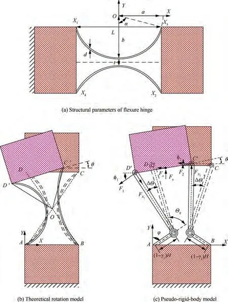
Fig. 7 Structure and pseudo-rigid-body model of symmetrical spring flexure hinge.
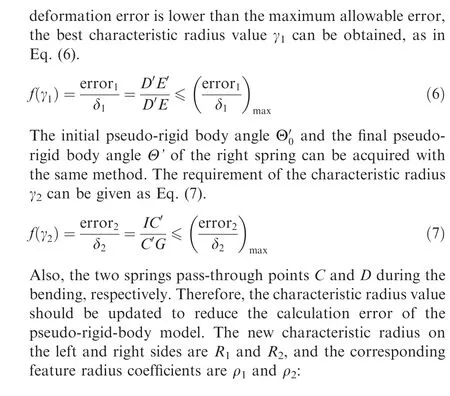
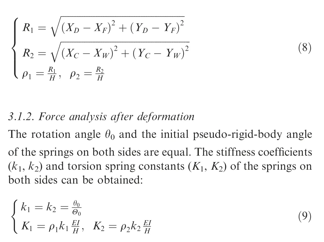
where,E and I are Young’s modulus(the hinge material is titanium alloy, E = 110 GPa) and the moment of inertia,respectively.
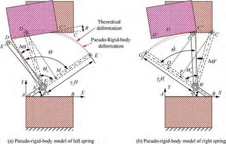
Fig. 8 Deformation of spring leaves.
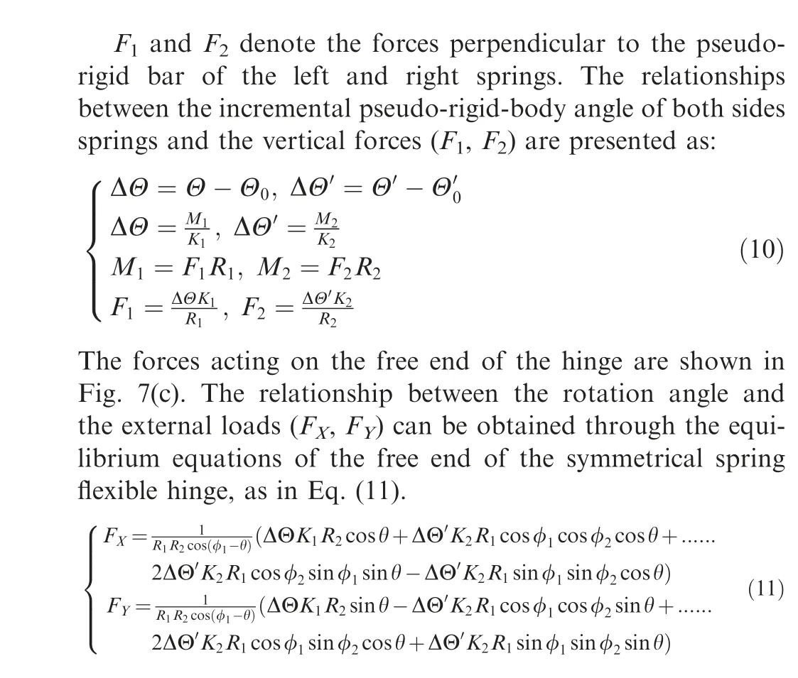
3.2. Parameter design of the flexure hinge
According to the skin and kinematic mechanism’s design results, the rotation angle and force of the hinge at the joint of the leading-edge mechanism and the skin can be known.Hence, the flexure hinge’s geometric parameters can be designed based on the relationships between the rotation angle and the force. The optimization is carried out to minimize the error between F,Fand the actual force f,f.The optimization results are shown in Table 4.

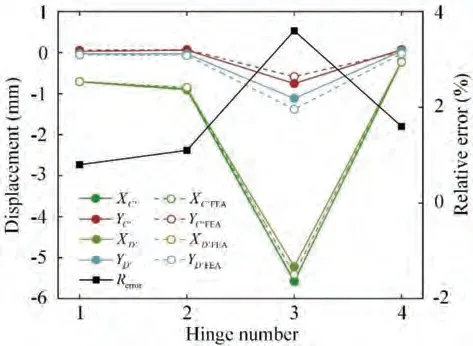
Fig. 9 Deformation error of symmetrical spring flexure hinge.

Table 4 Related parameters of flexure hinge.
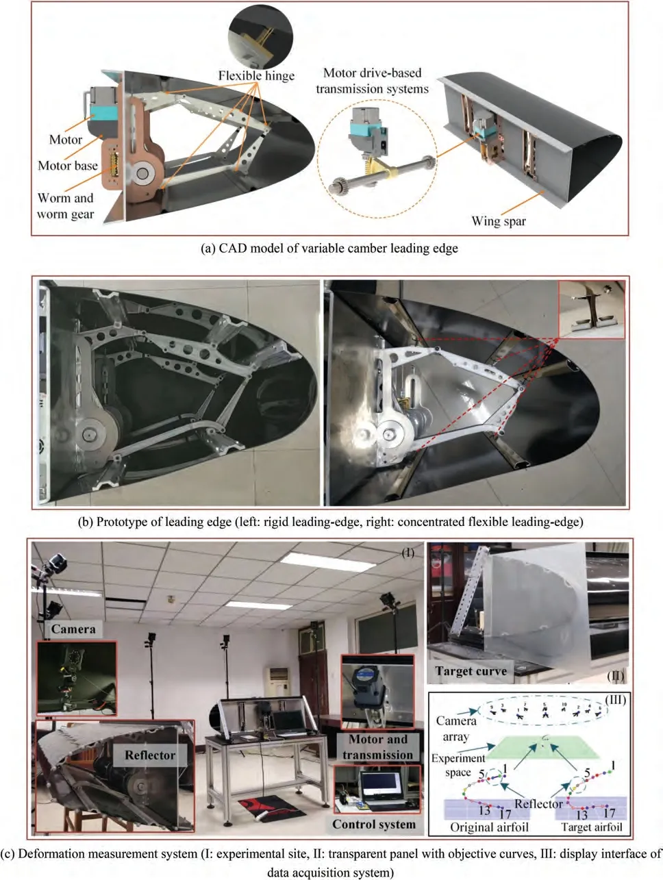
Fig. 10 Prototype and experiment platform of leading-edge.
The design results of the flexible hinge are verified by simulation. The error between the simulation and the calculation result is shown in Fig. 9. The graph illustrates the horizontal and vertical displacement of the hinge endpoint C’ (D’) and the relative error between the left spring endpoint’s deformation error and the overall deformation displacement of pseudo-rigid-body. It can be seen that the relative error of the flexible hinge is less than 4%. Moreover, the deformation error has a noticeable increase tendency with the increase of the bending angle, and the largest deformation error occurs at hinge 3, which has the largest rotation range.
4. Experiments and results
4.1. Prototype and experiment platform of leading-edge
In this paper, the kinematic mechanism is further optimized.The CCsegment with the larger span on the skin is selected as the design domain, the position of the new driving point is solved with the same approach, and the rigid-flexible conversion design of the hinge is carried out.
In order to achieve spanwise deformation simultaneously,the intermediate gear shaft is used for driving deformation of leading-edge. The worm gear is connected to the gear shaft through splines, and operated by a single motor. In this way,the input moment is reduced, and the leading-edge can be self-locked in the process of deformation. The computeraided design model of the concentrated flexure leading-edge mechanism is illustrated in Fig. 10(a).
Before conducting the contrast deformation experiments, a concentrated flexible leading-edge including flexure hinge and a rigid leading-edge with traditional hinge were designed and produced. The internal mechanisms of the two leading-edges are shown in Fig. 10(b), and the materials and weight of each part are shown in Table 5.Besides,the motion capture system is applied to collect the shape data of skin. The experimental site and the display interface of the data acquisition system are depicted in Fig. 10(c). With the wing as the centre, ten infrared cameras are arranged along the platform’s periphery,and seventeen reflectors are pasted along the skin’s side. The wing curve can be measured by the reflectors glued on the side of the leading-edge. A transparent panel with objective curves is fixed on the other side of the wing platform, which can display the error between the theoretical airfoil and the deformation curves of two leading-edge prototype.
4.2. Discussion of experiment results
The deformation of the leading-edge can be accurately achieved by controlling the rotations of the motor. The deformation curves of the rigid leading-edge and the concentrated flexure leading-edge are shown in Fig. 11(a). The black lines are the theoretical airfoil curve in the initial and final state.It can be seen that although the final airfoils of the two leading-edges are close to the theoretical curve, the shapes of the tip and lower skin are subtly different from the target airfoil. Fig. 11(b) shows that the measured deformation result of the concentrated flexure airfoil is approximately consistent with the theoretical airfoil and rigid leading-edge airfoil, but the ordinates of the 10th to 16th mark points are slightly off.The same deformation results of both ends of the leadingedge suggest that the drive system can achieve consistent deformation of the leading-edge along the span direction.
According to the position data of the marked points obtained by the data acquisition system, this paper further analyzes the error between the curve of the leading-edge prototype after morphed and the target airfoil, as shown in Fig.12.The histogram represents the horizontal/vertical coordinateserror between each marking point of the concentrated flexure leading-edge and the corresponding position of the rigid leading-edge/theoretical airfoil. The curve shows the relative error between each point’s horizontal/vertical error value and the airfoil thickness.

Table 5 Weight and material of components of two prototypes.
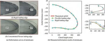
Fig. 11 Deformation results of two leading-edge prototypes.
It can be seen from Fig.12 that the largest deviations of the horizontal and vertical coordinates of the concentrated flexure leading-edge and the rigid leading-edge occurs at the 11th and 12th marking points, respectively, which are less than 4 mm and 4.5 mm.It is rather remarkable that the flexure hinge with the largest rotation angle during deformation is located between the 12th and 13th reflectors. A large rotation range for flexure hinge means that a greater rotation error. Therefore, the skin shape error between the rigid leading-edge and the concentrated flexure leading-edge will be relatively large in the proximity of the flexure hinge with the largest deformation angle. In addition, the maximum error of the horizontal and vertical coordinates of the concentrated flexure leadingedge and the theoretical airfoil occurs at the 7th and 12th marking points,which are less than 3 mm and 7.5 mm,respectively. These shape errors occurred at the tip of the leadingedge. There are two main reasons for these errors. First, there are machining and assembly errors in the rigid mechanism.Second, these errors can be amplified by the driving mechanism. When the flexure hinge was introduced into the rigid leading-edge, these mechanical errors were not eliminated,resulting in the difference at the tip between the flexible leading edge and the theoretical airfoil.The curve in Fig.12 illustrates that the relative errors of the corresponding marking points on the concentrated flexure leading-edge and the rigid leadingedge are both less than 1.5%,and the maximum relative error between the concentrated flexure leading-edge and the target leading edge is less than 2.2%, which verifies the rationality of the design of the drive mechanism and the feasibility of rigid-flexible conversion design.
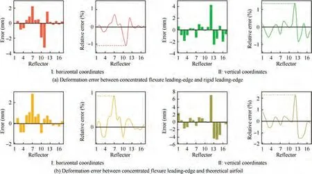
Fig. 12 Comparison of concentrated flexure leading-edge deformation.
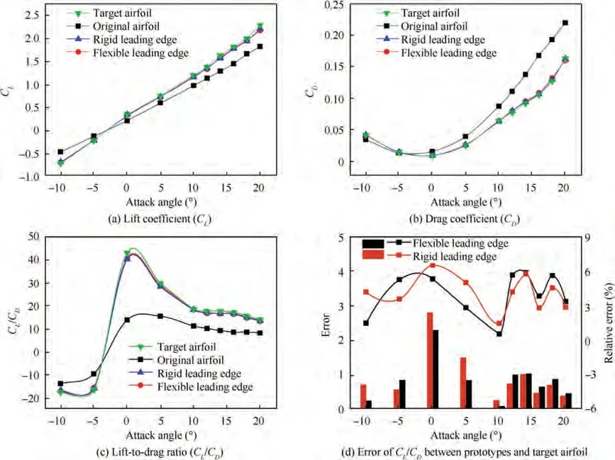
Fig. 13 Comparison of aerodynamic performances of four airfoils.
Fig. 13 compares the aerodynamic characteristics of the concentrated flexure leading-edge, rigid leading-edge and target airfoil in the final state.The lift coefficient(C),drag coefficient (C) and the lift-to-drag ratio (C/C) of the variable camber wing under different attack angles are presented. It should be mentioned that these simulation data are obtained at low speed,which is similar to the typical takeoff and landing state of aircraft. The overall change trends of the C, Cand C/Cof the three airfoil curves are consistent. As shown in Fig. 13(a), When the attack angle is more than -3°, the morphed airfoil’s lift coefficient is significantly greater than that of the original airfoil.When the angle of attack is 0°,5°,and 10°,the variable camber airfoil’s lift coefficient increases by 42%,20%,and 18.6%compared with the initial airfoil,respectively.And the improvement effect decreases as the attack angle increases.Fig.13(b)shows the original airfoil’s drag coefficient is more extensive than it of morphed airfoil when the attack angle greater than -4°. Further, Fig. 13(c) depicts the change in the lift-to-drag ratio of the wing before and after the deformation.It is clear that the C/Cincreased sharply during the attack angle from-5 to around 0 degrees but fell slowly as the attack angle increased.The maximum C/Cof the target airfoil is 45 when the attack angle is 0.87°,while the top C/Cof the original airfoil is 16.6 when the attack angle is 2.46°. In Fig. 13(d), the histogram corresponds to the absolute error of the lift-to-drag ratio between the rigid/flexible wing and the target airfoil, the curves with square markers represent the relative error. It can be seen that the difference in the lift-to-drag ratio between the concentrated flexure morphing wing and the target airfoil are small,the maximum value is less than 3. Due to the C/Cof the target airfoil is located at a relatively low level when the attack angle greater than 10°,the actual lift-drag performance between the three airfoil is not much different although the relative error value is close to 6%. In summary, this paper designed the leading-edge of variable camber can achieve ideal aerodynamic performance.
Furthermore, the airflow distribution of the concentrated flexure airfoil and original airfoil is illustrated in Fig. 14. At low angles of attack, the two airfoils’ surface airflow distribution is similar, and the airflow over the top of the wing flows smoothly. When the attack angle is 20°, the two airfoils’ pressure does not change significantly, but the original airfoil began to appear the trailing vortex and airflow separation.Moreover, the degree of airflow separation increases with the increase of the angle of attack. When the attack angle is 24°,the suction surface pressure distribution of the original airfoil is uneven, the airflow becomes turbulent, the trailing vortex gets larger, and the other vortex appears on the leading-edge.However, at the same attack angle, the pressure and airflow distribution on the flexible airfoil suction surface are relatively uniform, and there are only trailing vortices appeared on the airfoil. This indicates that the concentrated flexure leadingedge can inhibit flow separation and vortices’formation,delay the transition of the boundary layer and the airfoil’s stall.
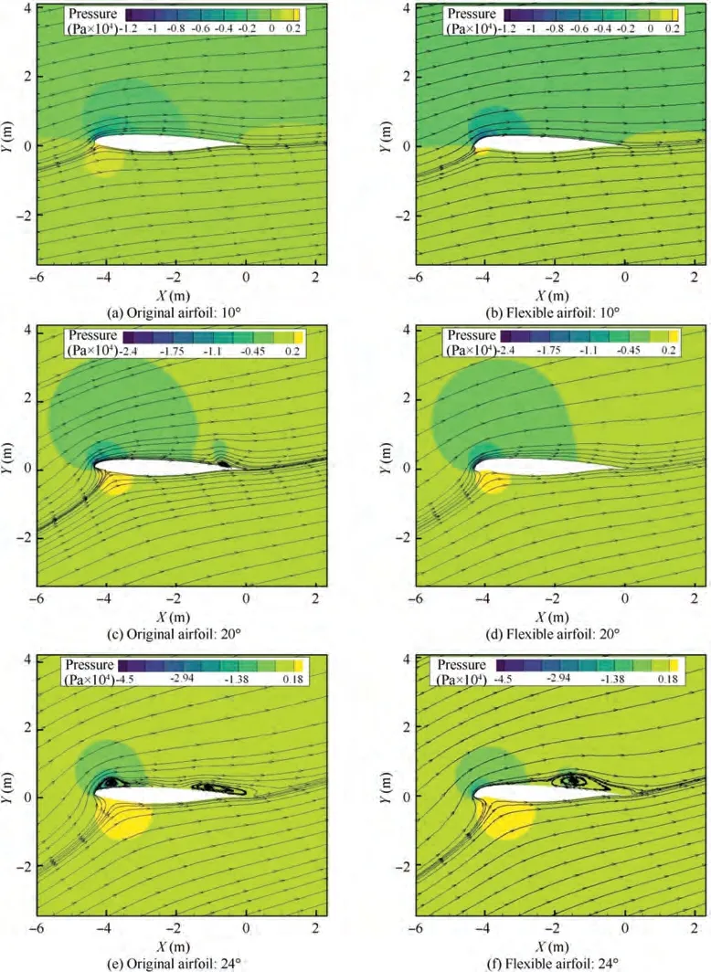
Fig. 14 Airflow distribution characteristics of two types of airfoils at different attack angle (10°, 20° and 24°).
5. Conclusions
(1) This paper designs a concentrated flexible leading-edge driven by the geared five-bar mechanism.The glass fibre composite sheet is used as the skin material, and the driving point of the skin is optimized according to the airfoil and load of the leading-edge. To improve the leading edge’s carrying capacity, a design scheme that the internal drive mechanism is rigidly connected to the skin is proposed. Combining with the advantages of flexible structure,the symmetrical spring flexure hinge designed by the pseudo-rigid body method is applied to the drive mechanism. Finally, the deformation performance of the concentrated flexible leading-edge is tested through comparative experiments,and the aerodynamic characteristics of the concentrated flexible leading-edge are analyzed in terms of the lift and drag performance as well as the airflow distribution.
(2) In this paper, the rigid-flexible conversion of the hinge only at the connection between the skin and the internal drive mechanism is carried out, and a similar flexible design for the revolute joint in the drive mechanism is considered later. Besides, the weight of the leadingedge structure can be reduced by topology optimization methods.Currently,relevant pneumatic loading tests are being carried out on the leading-edge prototype.
The authors declare that they have no known competing financial interests or personal relationships that could have appeared to influence the work reported in this paper.
This work is supported by National Natural Science Foundation of China(No.50975230),Natural Science Basic Research Plan in Shaanxi Province of China (No. 2017JM500), and National Natural Science Foundation of China (No.51375383).
