Electrochemical drilling of small holes by regulating in real-time the electrolyte flowrate in multiple channels
Jinxing LUO, Xiaolong FANG,*, Tao YANG, Di ZHU
a National Key Laboratory of Science and Technology on Helicopter Transmission, Nanjing University of Aeronautics and Astronautics, Nanjing 210016, China
b Jiangsu Key Laboratory of Precision and Micro-Manufacturing Technology, Nanjing University of Aeronautics and Astronautics, Nanjing 210016, China
KEYWORDS Electrochemical drilling;Small holes;Electrolyte flowrate;Real-time regulation;Machining stability
Abstract Electrochemical drilling (ECD) provides an alternative technique for drilling multiple small holes in difficult-to-machine materials in numerous industrial applications such as for aeroengines.The value and fluctuation of electrolyte flowrate can seriously affect the machining stability and hole quality in ECD. In particular, when drilling multiple holes, the distribution and fluctuations of the electrolyte flowrate in each channel could influence the uniformity of the electrolyte flowrate among multiple tube electrodes, thereby affecting the machining stability and the maximum feed rate.Thus,an eight-channel flow control system was developed to measure and regulate in real time the electrolyte flowrate supplied into each individual tube electrode. This paper proposes ECD of small holes with real-time flowrate control to improve the uniformity of electrolyte flowrate in each tube electrode and reduce the fluctuations in the electrolyte flowrate.In single-hole drilling, when the electrolyte flowrate was regulated in real time, the hole quality and machining stability were considerably better than without regulation. This is because the electrolyte flowrate remains basically constant,which stabilizes the flow field.Moreover,by considering the hole profile,it was found that an electrolyte flowrate of 200.0 mL/min can be acceptable for ECD of small holes.When the eight-channel flow control system was used in multiple-hole drilling,the uniformity of the electrolyte flowrate in each tube electrode was obviously improved,which led to a more stable process. Additionally, the maximum feed rate can attain 2.40 mm/min in multiple-hole drilling. Based on these findings, a matrix (5 × 32) of multiple small holes was successfully fabricated with a satisfactory diameter consistency, as the machining stability and machining efficiency had been enhanced.
1. Introduction
Structures with multiple small holes have been extensively used in functional components (for example, heat shields and floating tiles) to increase aeroengine performance.Such holes,which have diameters of 1.0-4.0 mm, are generally made of difficult-to-cut materials, such as nickel-based alloys and titanium alloys.Mechanical drilling encounters various problems, such as burr formation and high tool wear, because of the hardness and strength of these materials.Laser drilling and electrical discharge drilling are effective for machining holes in difficult-to-cut materials, but there are normally suffered the drawbacks of heat-affected zones and even microcracks, which are strictly unacceptable in the aeronautical industry.This somewhat limits the application of laser drilling and electrical discharge drilling to aeroengines, especially for products requiring a good surface integrity.
Electrochemical drilling(ECD)utilizes a side-insulated hollow tube as the cathode tool and removes anodic material via controlled electrochemical reactions in an electrolytic cell.It inherits various merits from electrochemical machining,including independence from the material mechanical properties, an absence of tool wear and residual stresses, and good surface integrity.Thus, ECD has attracted much attention as an alternative method for producing small holes. In industry, acid electrolyte solutions are employed for drilling small holes, which avoids the production of insoluble precipitates and improves the process stability.However, acid electrolytes are unfriendly to the environment and their waste disposal is expensive. Thus, neutral salt solutions have been increasingly adopted in ECD.
When a neutral salt electrolyte is used,the dissolved metallic ions usually react with hydroxyl ions to form insoluble waste products, which may accumulate progressively and block the machining gap. This can exert a negative impact on the process stability and the machining accuracy. Therefore, some methods have been proposed to sweep machining products away rapidly in electrolyte flow pattern. Using a pulsed current can enhance the removal of electrolysis products during the pulse-off time and lead to stable machining.A pulsating electrolyte flow was applied to improve heat transfer, the removal of waste products, and the surface profile in ECD.Moreover, a constant electrolyte flow was implemented in ECD to improve the removal of metal sludge and Joule heating when drilling deep and small holes.
Many reliable achievements have arisen from years of research into the electrolyte flow condition to improve the process stability. Rajurkar and Zhu noted that an orbital movement of the tool resulted in a uniform electrolyte flow in ECD, which could enhance the machining stability as well as the machining accuracy.Hewidy et al. found that an orbital movement caused the side machining gap to undergo periodic expansion and contraction, which was helpful for excluding the machining products.And, Hewidy et al. hybridized low-frequency vibrations to improve the physical condition and the renewal of the electrolyte in the inter-electrode gap,which increased the machining stability and surface quality.Wang et al.presented a method for ECD with vacuum extraction of electrolyte, which reduced the formation of striated jet defects and enhanced the stability of the machining process.Li et al. studied the characteristics of vacuum extraction ECD in drilling inclined cooling holes and investigated the influence of key process parameters.Zhang et al. optimized the processing parameters to eliminate spikes at the hole bottoms and thus, improved the process stability.Besides, other attempts have been made to enhance the machining accuracy.Zhu et al. proposed a dual-pole tool to minimize the current density at the side gap and reduce stray removal there,thereby improving the machining accuracy.Fang et al.applied a positive potential from an auxiliary electrode to the workpiece and enhanced the hole exit accuracy.
Moreover, the flexibility in simultaneously drilling numerous holes makes ECD a feasible technique for producing multiple small holes. In multiple-hole drilling, the electrolyte usually flows into an electrolyte-dividing manifold and then is divided to each tube electrode.Zhu et al.experimentally verified the feasibility of electrolyte extraction in ECD of multiple holes.In addition, Fang et al. optimized the structural parameters of electrolyte-dividing manifold to enhance the distribution of the electrolyte flowrate.However,the electrolyte flux divided into each tube electrode is governed by dimensions of the structure and the distribution of the electrolyte-dividing manifold.Moreover,it is hard to measure and control the electrolyte flowrate. As described in these literatures, most attention has focused on improving the improve the electrolyte flow,and few studies have considered the variations in the electrolyte flowrate during machining. As the electrolyte flowrate changes, common defects, like threading and bulrushing,may occur on the hole sidewall, which deteriorate the hole quality and the machining stability.Additionally,there is little information available in literature about how the electrolyte is individually supplied to multiple tube electrodes. Fluctuations of the electrolyte flowrate during drilling may have a negative effect on machining stability and hole quality.In ECD of multiple holes, the distribution and fluctuation of the electrolyte flowrate commonly depend on the electrolyte-dividing manifold, which may further influence the uniformity of the electrolyte flowrate among multiple tube electrodes, thereby affecting the processing stability and the consistency of hole diameters.
Hence,an eight-channel flow control system was developed to measure and real-time regulate the electrolyte flowrate supplied into each individual tube electrode. In this paper, the eight-channel flow control system was used in ECD to improve the uniformity of the electrolyte flowrate in each tube electrode and reduce the fluctuations of the electrolyte flowrate. Subsequently, experiments were conducted to investigate the effects of fluctuations in the electrolyte flowrate on single-hole and multiple-hole drilling, respectively. The influence of different electrolyte flowrates on hole profiles were experimentally determined. Moreover, the maximum feed rates of singlehole and multiple-hole drilling were obtained with the different electrolyte flowrates.Based on these findings,a matrix(5×32)of multiple small holes was successfully fabricated with a satisfactory diameter consistency. Thus, the machining stability and machining efficiency were enhanced.
2. Principles
2.1. Electrochemical drilling
In ECD, a hollow metal tube covered with an insulation layer is used as the cathode tool, whereas the workpiece is acted as an anode electrode. During drilling, the electrolyte is supplied into the tube electrode and then flows at high speed through the inter-electrode gap. When an electric voltage is applied,the anodic material is electrochemically dissolved and a hole is gradually generated by continuously feeding the tube electrode, as schematically illustrated in Fig. 1.
The electrolyte flux directly determines the electrolyte flow velocity at the machining gap,which removes machining products and accelerates the renewal of electrolyte in the gap.The electrolyte flow velocity though the inter-electrode gap usually ranges from about 3.0 to 30.0 m/s. When the electrolyte flow velocity is too low,there is Joule heating and electrolytic products, such as insoluble products and gas bubbles, accumulate in the machining gap, which prevents electrolyte refreshment,thereby making the machining unstable, and can even lead to a short circuit. These effects directly reduce the machining efficiency and machining accuracy. However, when the electrolyte flow velocity is too high (≥30.0 m/s), its effect on ECD is not obviously improved, as may be expected.
In addition,as the tube electrode continues to feed,the status of electrolyte flow changes,especially in the initiation stage and the breakthrough stage.The electrolyte flow resistance can vary during machining, causing fluctuations in the electrolyte flowrate. To avoid these crises, the electrolyte is flowed through the machining area at a high and basically constant flowrate.
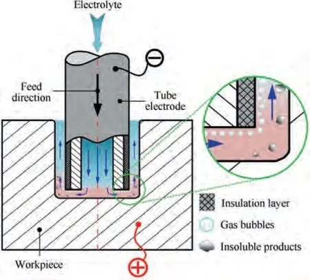
Fig. 1 Schematic diagram of electrochemical drilling (ECD).
2.2. Real-time regulation of electrolyte flowrate
The real-time regulation of the electrolyte flowrate implemented in this paper is illustrated in Fig. 2. The electrolyte flowrate in a flow channel was firstly measured with a laminar flowmeter and the difference from the set flowrate was calculated. The difference was immediately sent to a process controller, which fed back a signal to the proportional regulating valve. This valve adjusted the valve clearance until the detected flowrate was close to the set point. The control of electrolyte flowrate is independent of the electrolyte pressure. Hence, this is closed-loop control and real-time regulation of the electrolyte without any intervention.
Based on the electrolyte flowrate control for one branch,the electrolyte flowrate control of eight channels was successfully achieved by designing eight parallel channels. Thus, the electrolyte flowrates of eight channels were regulated in real time independently without any intervention.A schematic diagram of ECD of multiple holes with real-time regulation of the electrolyte flowrate in eight channels is presented in Fig. 3.
3. Experimental procedures
3.1. Development of eight-channel flow control system
Thus, an eight-channel flow control system was successfully built and implemented. Its main functions are as follows:
(1) Real-time detection of the electrolyte flowrate and pressure in each channel;
(2) Automatic regulation of the electrolyte flowrate to attain the set point in each channel;
(3) Capture of the electrolyte flowrate and pressure in each channel.
The system has hardware and software. Block diagram of the system prototype is presented in Fig. 4. It has four main parts:
(i) Object module: This simultaneously records the electrolyte flowrate and pressure signals of each channel and regulates in real time the electrolyte flowrate;
(ii) Sensing and control module: This has eight liquid mass flow controllers (ACU10-LC; Beijing Precision, China)and eight pressure transmitters (AE-S; Aire Senor,China);
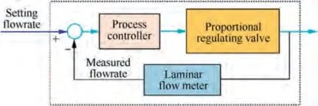
Fig. 2 Closed-loop control diagram for real-time regulation of electrolyte flowrate.
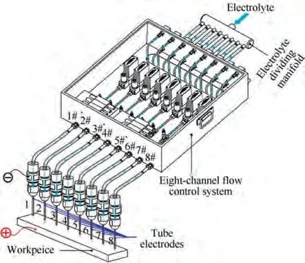
Fig. 3 Schematic diagram of ECD of multiple holes with eightchannel flow control system.
(iii) Communication module: This transmits data via two serial hubs(RS485)between the hardware and software;
(iv) System software: This programed by writing on LabVIEW2018.
The software system adopted the modular design, thereby increasing the flexibility of the system. The hardware was assembled and then synergistically debugged with the system software, as illustrated in Fig. 5. The pressure pump was used in the debugging and the measurements of flowrate deviation.During debugging, it was found that the control of the electrolyte flowrate was best when the response time was 200.0 ms, as previously reported by Zhang et al.The deviations in the flowrate were measured to be less than ± 1.56% overall. The properties of the system are listed in Table 1.In summary, the system performance was acceptable for ECD of small holes.
3.2. Experimental setup
The experimental system for ECD of small holes comprises a machine tool, a motion control system, a direct current (DC)power source, the eight-channel flow control system, an electrolyte circulating system, a holder for the multiple tube electrodes, and other fixtures, as shown in Fig. 6.
The workpiece was installed on a platform,while the holder for the tube electrodes was mounted on a spindle that could move along the X-,Y-,and Z-axes.The motion control system(SINUMERIK 808D;Siemens,Germany)was used to control the tool motion. The DC power source (IT6922A; Itech,China) provided the power for the electrochemical dissolution reactions. The electrolyte circulation system comprised two electrolyte tanks (an apinoid electrolyte tank and a dreggy electrolyte tank), a pump, and a filter. The eight-channel flow control system was used to measure and auto-regulate the electrolyte flowrate of each channel. The holder for the multiple tube electrodes has a connecting block, eight tube electrodes,and a tube guide sleeve. The photograph of the experimental system for machining small holes is illustrated in Fig. 7.
Herein, the machining parameters for experiments were chosen according to previous experimental trials. Tube electrodes were primarily cleaned with acetone and anhydrous ethanol in an ultrasonic cleaning machine. After that, tube electrodes were coated with a 30 μm thick insulation layer on its side wall via electrophoresis. The martial of insulation layer is epoxy resin, which has good electrical insulation. The experimental conditions are listed in Table 2.When electrolyte flowrate was not regulated, the electrolyte was directly supplied by a pressurized pump, which is like ECD with constant electrolyte pressure.
After machining, the workpiece was placed in an ultrasonicator and cleaned with anhydrous ethanol and then acetone.The hole shapes and hole bottom morphologies were inspected with a surface profiler (VR-5200; Keyence, Japan). The hole diameters were measured with an optical microscope (STM7-SFA; Olympus, Japan). The hole profiles were examined with a scanning electron microscope (S-3400 N; Hitachi, Japan).The current signals were recorded during the experiment by a data acquisition unit embedded in the DC power unit.
4. Results and discussion
4.1. Single-hole drilling
Fluctuations in the electrolyte flowrate during machining should have an impact upon the machining current stability and the hole quality.It was conducted to investigate the effects of fluctuations in the electrolyte flowrate on single-hole drilling and the effects of the electrolyte flowrate on the hole profile.
4.1.1.Effects of regulating the electrolyte flowrate on single-hole drilling
As the electrolyte flowrate fluctuates during drilling, the flow field in the machining area also changes, which has a distinct impact on single-hole drilling. This subsection describes two sets of experiments in which single holes were machined. For the first set,the electrolyte flowrate was regulated in real time,and the set point for the electrolyte flowrate was 200.0 mL/min. For the other set, there was no regulation. The other machining parameters are as listed in Table 2.

Fig. 4 Architecture of flow control system.
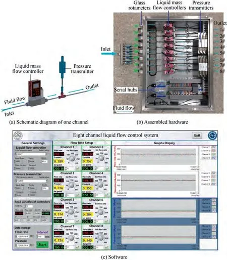
Fig. 5 Eight-channel flow control system.
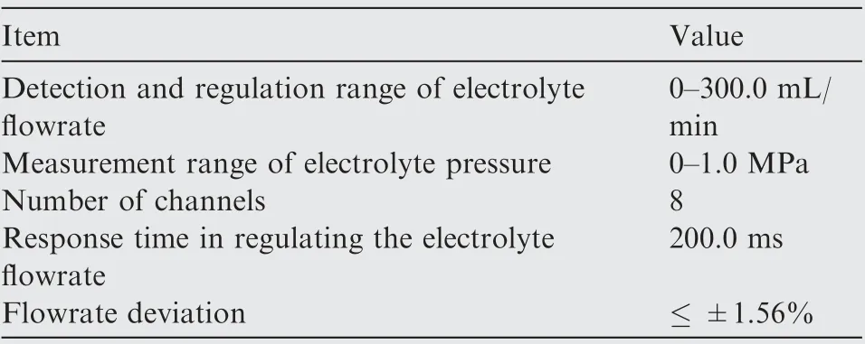
Table 1 Properties of the eight-channel flow control system.
During machining, the electrolyte flowrate is fluctuated, as shown in Fig. 8(a). These fluctuations make the flow field unstable. And, it is prone to cause tube electrode vibration,which induces fluctuation in the machining current.The fluctuations in machining current are considered to be a reflection of machining stability. Consequently, the machining current experienced large fluctuations with a maximum ratio of 8.32%, as illustrated in Fig. 8(b). As expected, defects, like threading and bulrushing,occurred on the machined hole sidewall (Fig. 9(a)). These significantly increased the surface roughness of the machined hole sidewall, such that R= 2.5 03 μm.This can be attributed to the fluctuations in electrolyte flowrate, which reduced the transport of waste products and hence deteriorated the hole quality. Meanwhile, it can be seen that the electrolyte flowrate fell during the initiation stage because the resistance to flow increased as the tube was fed.
With real-time regulation, the electrolyte flowrate fluctuated slightly and remained basically consistent (Fig. 8(a)),which stabilized the flow and the electric fields, and consequently improved the machining current stability and hole quality.It is evident that when the electrolyte flowrate was regulated in real time, the fluctuations of the machining current were smaller and the fluctuation amplitude was only 2.13%,as shown in Fig.8(b).A relatively steep hole sidewall was produced without any obvious defects, as revealed in Fig. 9(b).Moreover, the surface roughness of the hole sidewall was 1.854 μm.By comparison,the hole shape and hole quality were considerably better than without regulation.In summary,realtime regulation of the electrolyte flowrate improved the hole quality and the machining stability in ECD to a certain extent.Therefore, the electrolyte flowrate was subsequently regulated in real time in single-hole drilling.
4.1.2. Effects of electrolyte flowrate on the hole profile
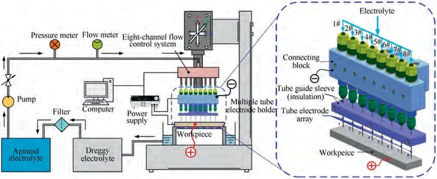
Fig. 6 Schematic diagram of experimental system.
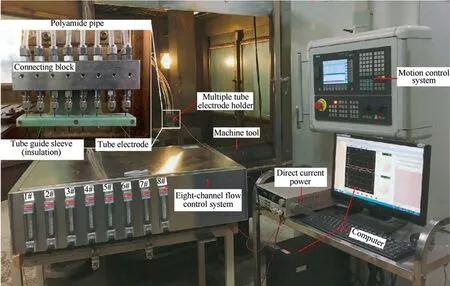
Fig. 7 Photograph of experimental system used for machining small holes.
The electrolyte flowrate is important in machining a single hole, so it is necessary to determine the right electrolyte flowrate. Herein, the hole profile includes the hole shape, the hole sidewall and the morphology of hole bottom. This section describes experiments that observed the hole sidewall and measured the hole bottom morphology. The electrolyte flowrate was varied from 100.0 mL/min to 240.0 mL/min with increments of 20.0 mL/min. The other machining parameters are as listed in Table 2.
Fig. 10 shows cross sections of single holes machined with eight electrolyte flowrates. It is clear that when the electrolyte flowrate was less than 140.0 mL/min, the hole entrances had rounded corners, accompanied by a larger abnormal spike at the hole bottom, especially so with an electrolyte flowrate of 100.0 mL/min (i.e., the average flow velocity was 3.23 m/s).Moreover, it is found that the hole diameter and roundness error typically change little with the electrolyte flowrate, as presented in Fig. 11(a).
When the electrolyte flowrate was 160.0 mL/min or less,the hole sidewall had defects, like threading. When the electrolyte flowrate was less than 200.0 mL/min,the hole bottom encountered irregular spikes, as shown in Fig. 12. This should be ascribed to these electrolyte flowrates were insufficient to remove the electrolytic products, thereby causing a deterioration of the flow and variations in the electrolyte conductivity.Thus, the distributions of the flow and the electric fields changed significantly, which produced variations in the hole sidewall and abnormal spikes on the hole bottom. Therefore, the surface of the machined hole sidewall was relatively rough,as shown in Fig. 11(b). For higher electrolyte flowrates, the threading and irregular spikes gradually reduced and disappeared at 200.0 mL/min (i.e., the average flow velocity was 6.87 m/s). This may be because that with an increase in flow velocity, the waste products were effectively excluded and thematerial dissolution rate was relatively consistent, which improved the hole quality. Moreover, Rmeasurements of the machined holes show that the surface quality of hole sidewall was better. However, when the electrolyte flowrate was 240.0 mL/min (i.e., the average flow velocity was 7.87 m/s),the machined hole sidewall was undesired. The reason for this is believed to be due to the high electrolyte flowrate and the low electrode feed rate.Based on this comprehensive consideration of the hole profile, the machining performance obtained with an electrolyte flowrate 200.0 mL/min was found to be acceptable for ECD of small holes.
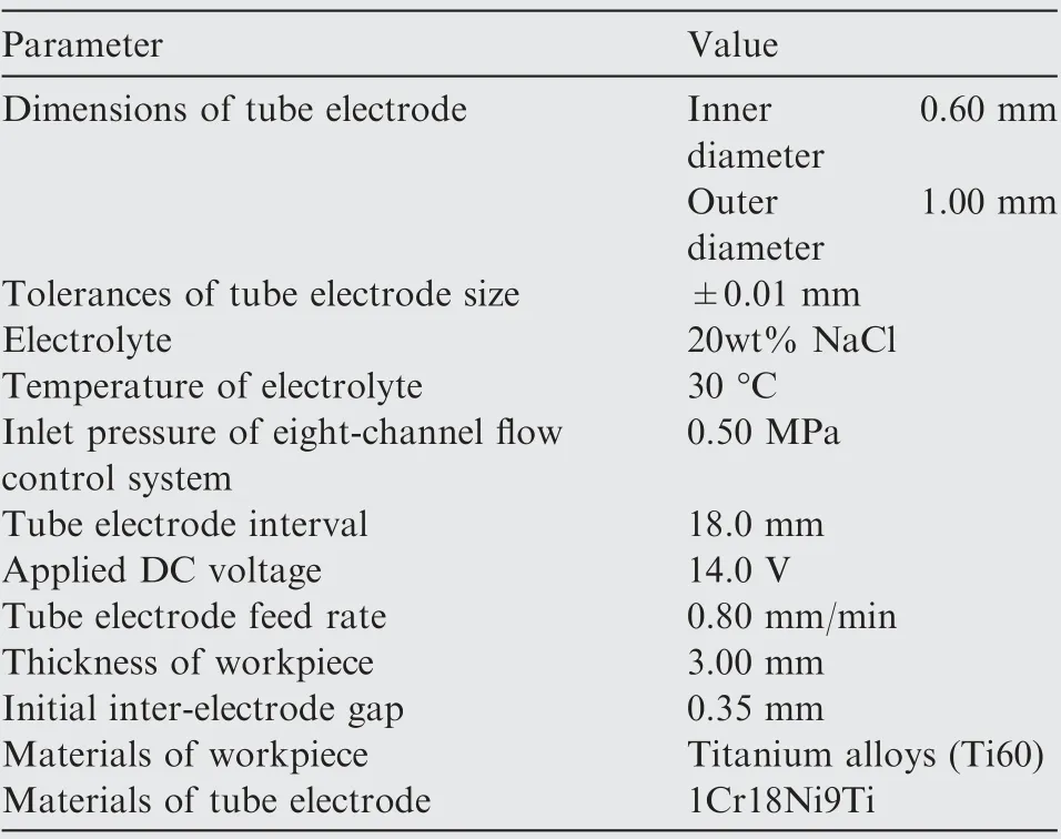
Table 2 Experimental conditions for ECD of small holes.
4.1.3. Effects of electrolyte flowrate on maximum feed rate
In ECD,the electrode feed rate is a major concern in industrial production. A higher feed rate is always preferable as it improves machining efficiency. Experiments with different electrolyte flowrates were conducted to test the maximum feed rate in single-hole drilling. In these sets of experiments, the electrolyte flowrate was varied from 100.0 to 240.0 mL/min in increments of 20.0 mL/min. The other processing parameters are as listed in Table 2.
The experimental results in Fig.13 show that the maximum feed rate increased from 1.80 to 2.70 mm/min as the electrolyte flowrate increased from 100.0 to 240.0 mL/min in single-hole drilling. This may be because increasing the electrolyte flowrate significantly improved the removal of machining products and promoted the electrolyte refreshment in the machining area,which increased the maximum feed rate. However, when the electrolyte flowrate exceeded 220.0 mL/min,the maximum feed rate did not increase significantly.The reason for this may be summarized in two respects. On the one hand, a high feed rate leads to a smaller hole diameter, as shown in Fig. 13.The frontal gap and lateral gap are smaller, which is adverse for the excretion of electrolytic products and the renewal of the electrolyte in the machining gap.Consequently,a short circuit or other undesired machining situations can occur if the feed rate is too high. On the other hand, the amount of electrolytic products increases as the feed rate increases.Although the electrolyte flowrate also increases, it is hard to neutralize the effects of electrolytic products at the same time. If the machining products cannot be removed quickly enough, the maximum feed rate cannot increase. It is evident that increasing the electrolyte flowrate blindly will not necessarily increase the maximum feed rate.
4.2. Multiple-hole drilling
In multiple-hole drilling,the uniformity of the electrolyte flowrate among the multiple tube electrodes is critical, as it affects the machining stability and the maximum feed rate.
4.2.1. Effects of regulating the electrolyte flowrate on multiplehole drilling
Two sets of comparative experiments were carried out to machine multiple holes, namely with the electrolyte flowrates in the eight channels regulated or not. In each set, three rows of small holes were machined. The machining parameters are given in Table 2. The set point for the electrolyte flowrate of each channel was 200.0 mL/min.
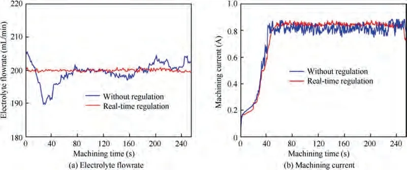
Fig. 8 Electrolyte flowrates and machining currents for single holes.

Fig. 9 Single holes machined with and without real-time regulation of electrolyte flowrate.
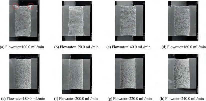
Fig. 10 Cross sections of single holes machined with different electrolyte flowrates.
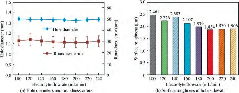
Fig. 11 Hole diameters, roundness errors, and surface roughness of hole sidewalls for different electrolyte flowrates.

Fig. 12 Hole bottom morphologies under three kinds of electrolyte flowrate.
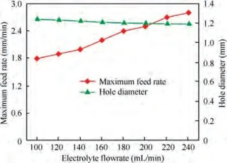
Fig. 13 Maximum feed rate and hole diameters obtained with different electrolyte flowrates.
When the electrolyte flowrates of each channel were not regulated in real-time, they were non-uniform and fluctuated during machining, as plotted in Fig. 14. It can be seen that the electrolyte pressures were remained constant and that the electrolyte flowrates in each tube electrode were different, as listed in Table 3.This is because the electrolyte flowrate in each channel was governed by the electrolyte-dividing manifold,which caused a maldistribution and fluctuations in the electrolyte flowrate. As a consequence, the flow and electric fields of each hole drilling varied and were quite different in multiple-hole drilling, which may deteriorate the machining current stability and hole shape, as presented in Fig. 15 and Fig. 16. Hence, the machining current inevitably has larger fluctuations with maximum ratios of 17.14%, especially in the initial stage. The diameters of multiple machined holes were 1.348 ± 0.053 mm and stray corrosion occurred around some holes. This means that the electrolyte flowrates in the eight channels were indeed distributed unevenly and fluctuated, which results in poor multiple-hole machining.
When the eight-channel flow control system was used for multiple-hole drilling, the electrolyte flowrates in the eight channels were regulated in real time and remained basically constant, as shown in Fig. 17(a). It indicated that the uniformity of the electrolyte flowrate in each channel was satisfactory. This is because the volume of electrolyte ejected from each tube electrode was nearly consistent all the time.Accordingly, the uniformity of the electrolyte flowrate in each tube electrode was prominently improved,which stabilized the flow field in each hole and enhanced the consistency of electrolyte refreshment in the machining area. The higher uniformity of the electrolyte flowrate in each tube electrode made the multiple-hole drilling more stable. As a result, the machining current fluctuated only slightly and the maximum ratio of fluctuations was 3.07%, as depicted in Fig. 15. These current waveforms meanwhile manifested that the machining current stability in ECD of multiple holes is more stable and less perturbed than without regulation. The diameters of multiple machined holes (Fig. 18) are 1.343 ± 0.036 mm with acceptable consistency. Moreover, the hole quality and roundness error were considerably better than without regulation.Hence,when the electrolyte flowrates in the eight channels were regulated in real time in multiple-hole drilling, the machining stability was better and the diameters were more consistent, to a certain extent.
When the eight-channel flow control system was used for multiple-hole drilling, the electrolyte pressure in each channel is recorded,as presented in Fig.17(b).The electrolyte pressure increased in the initiation stage and remained constant in the normal stage, whereas it dropped rapidly in the breakthrough stage.When the other conditions were kept the same,the pressure increased with a decrease of the area that the electrolyte flowed through, and vice versa. Because the electrolyte outlet shrank in the initiation stage (Fig. 19(b)), the electrolyte pressure increased. During the normal stage (Fig. 19(c)), the electrolyte outlet remained constant; thus, the electrolyte pressure was stable. When the tube broke through the bottom wall of the workpiece (Fig. 19(d)), the electrolyte outlet expanded suddenly and the electrolyte pressure dropped slightly. Note that each channel was worked independently and they did not interfere with each other, regardless of the electrolyte flowrate or electrolyte pressure. This implies that the flow resistance for each hole was quite different in ECD of multiple holes.
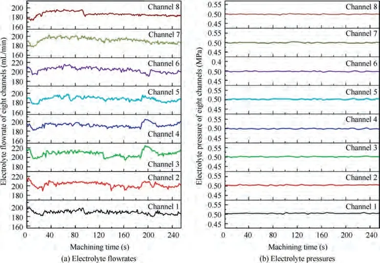
Fig. 14 Electrolyte flowrates and pressures in eight channels without regulation.
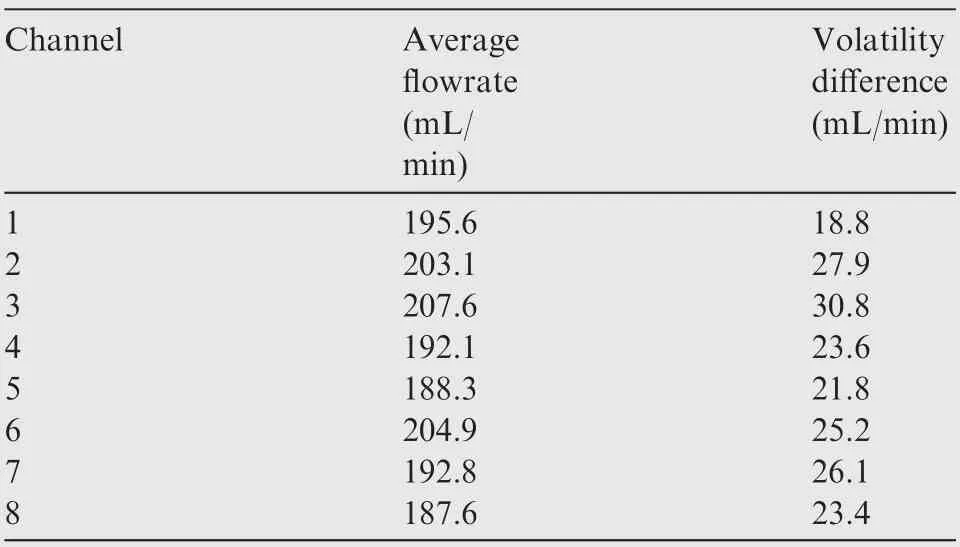
Table 3 Electrolyte flowrates in eight channels without regulation.
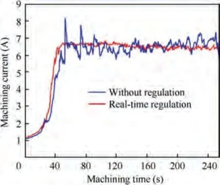
Fig. 15 Machining currents when multiple holes were drilled with and without regulation.
Thus,it is certain that an eight-channel flow control system not only can improve the uniformity of the electrolyte flowrate in each tube electrode but can also stabilize the electrolyte flowrate.It can be concluded that in multiple-hole drilling,regulating the electrolyte flowrate in each tube electrode to ensure it is consistent improves the uniformity of the electrolyte flowrate among multiple tube electrodes, thereby enhancing the machining stability and the consistency of the hole diameter.
4.2.2. Effects of electrolyte flowrate on maximum feed rate
In multiple-hole drilling, the maximum feed rate is the highest feed rate of an arrayed tube electrode at which the short circuit or spark events cannot occur in any hole drilling. In these sets of experiments, the electrolyte flowrate varied from 100.0 to 240.0 mL/min with increments of 20.0 mL/min.The other processing parameters were as given in Table 2.Note that the electrolyte flowrate was the same for each channel.
Fig. 20 shows that the maximum feed rate in ECD of multiple holes increased from 1.40 to 2.40 mm/min as the electrolyte flowrate increased from 100.0 to 240.0 mL/min. Note that the maximum feed rate in multiple-hole drilling is lower than single-hole drilling at the same electrolyte flowrate. This is because in the initiation stage, the distributions of the flow field and the electric field for each hole drilling changed radically and were quite different and it was difficult to ensure that the material removal rate was consistent in multiple-hole drilling. In the experiments, short circuits and even sparking usually occurred during the initiation stage, which restricted the maximum feed rate in multiple-hole drilling. Interestingly,the means and standard deviations of the hole diameters initially decreased with an increase of the maximum feed rate but subsequently hardly changed. It can be concluded that in ECD of multiple small holes, a higher electrolyte flowrate can result in a higher feed rate and a satisfactory diameter consistency, at least in a certain range.
5. Fabrication of multiple small holes
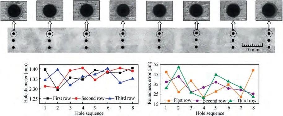
Fig. 16 Multiple holes machined without regulating electrolyte flowrates in eight channels.
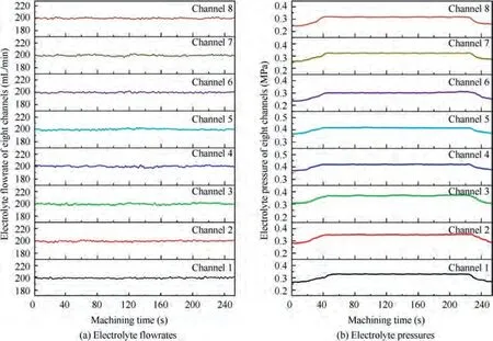
Fig. 17 Electrolyte flowrates and pressures in eight channels with real-time regulation.
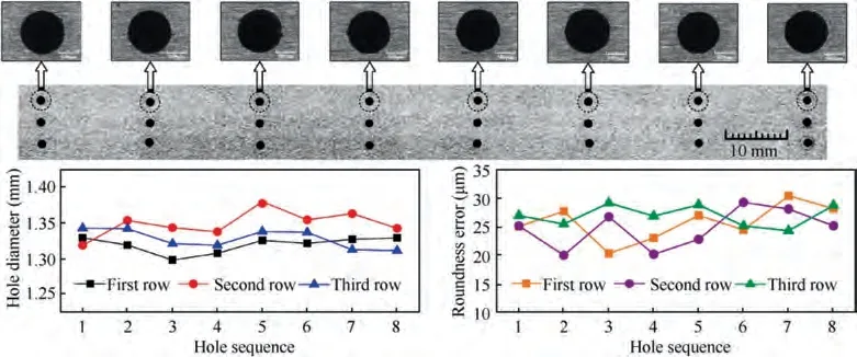
Fig. 18 Multiple holes machined by regulating electrolyte flowrates in eight channels.
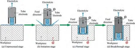
Fig. 19 ECD process of a through hole is commonly divided into four stages.
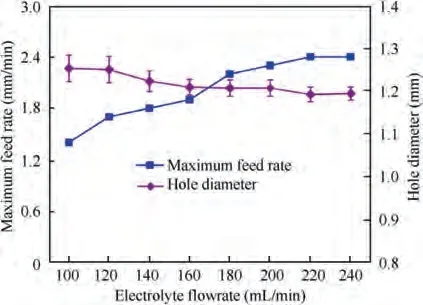
Fig. 20 Maximum feed rate and hole diameters with different electrolyte flowrates in multiple-hole drilling.
Industrial products usually have hundreds or thousands of closely spaced small holes. They can be processed in batches by scheduling the tool path of the multiple tube electrodes holder,as illustrated in Fig.21.First,a line of eight holes with a larger center distance were machined simultaneously(Fig.21(a)).The electrode holder was then shifted along the X-axis and more small holes were drilled between the original holes. This process was repeated until 32 holes had been drilled in a row with a small center distance(Fig.21(b)).When the first row of small holes was finished,the holder was shifted along the Y-axis and another row of holes was produced in the same way.This was repeated until a matrix of closely spaced small holes was fabricated (Fig. 21(c)).
Using this method,a matrix(5×32)of multiple small holes was fabricated. The machining conditions were as follows:applied DC voltage 14.0 V, electrode feed rate 1.80 mm/min,and electrolyte flowrate 200.0 mL/min. The other machining parameters are as listed in Table 2.
Measurements of small machined holes shown in Fig. 22 revealed that the hole diameters were 1.229 ± 0.027 mm,showing that the hole diameters had satisfactory dimensional consistency.The maximal roundness error of all the machined holes was 29.73 μm. The current waveforms demonstrate that the current had good stability and there were no large fluctuations, as plotted in Fig. 23. Note that the non-machining area retained its original high surface quality and there was no obvious stray corrosion.This indicates that a dense array of multiple small holes can be obtained by designing the tool path properly. Therefore, this proposed method can be used to machine a matrix type multiple small holes, thereby granting a superior performance to ECD with respect to its prominent machining capability.
6. Conclusions
This paper proposed ECD of small holes with real-time flowrate control to improve the uniformity of the electrolyte flowrate among multiple tube electrodes and reduce the fluctuations in the electrolyte flowrate. Based on the experimental results and analysis, the conclusions can be summarized as follows.
(1) An eight-channel flow control system was successfully developed. It can measure and regulate in real time the electrolyte flowrate supplied into each individual tube electrode.
(2) It is found that when the electrolyte flowrate fluctuates during machining,the machining stability and hole quality are deteriorated, whether in single-hole or multiplehole drilling.

Fig. 21 Schematic of pre-planned tool path used to manufacture a matrix of multiple holes.

Fig. 22 A matrix (5 × 32) of multiple small holes with a hole center distance of 4.50 mm.
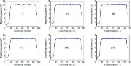
Fig. 23 Current signals captured when machining multiple holes.
(3) In single-hole drilling, when the electrolyte flowrate is regulated in real-time, it fluctuates slightly and remains basically constant, which is beneficial to stabilize the flow and electric fields. Accordingly, the hole quality and machining stability are considerably better than without real-time regulation. By considering the hole profile, an electrolyte flowrate of 200.0 mL/min was found to be acceptable for ECD of small holes.
(4) In multiple-hole drilling, when the eight-channel flow control system was used, the uniformity of the electrolyte flowrate among the multiple tube electrodes was obviously improved, which made the process more stable. Moreover, the maximum feed rate can be attained 2.40 mm/min.
(5) Based on the above conclusions, experiments verified that a matrix(5×32)of multiple small holes with a center distance of 4.50 mm was successfully fabricated by carefully planning the tool path. The hole diameters had good dimensional consistency and the machining process was stable.
The authors declare that they have no known competing financial interests or personal relationships that could have appeared to influence the work reported in this paper.
This project was supported by the Joint Funds of the National Natural Science Foundation of China and Guangdong Province (No. U1601201), and the National Natural Science Foundation of China for Creative Research Groups (No.51921003). The authors would also like to thank the editors and referees for their insightful comments and suggestions.
