In-process adaptive milling for large-scale assembly interfaces of a vertical tail driven by real-time vibration data
Xiong ZHAO, Linyu ZHENG,*, Lu YU
a School of Mechanical Engineering and Automation, Beihang University, Beijing 100191, China
b C919 Division, Shanghai Aircraft Manufacturing Co., Ltd, Shanghai 201324, China
KEYWORDS Adaptive milling;Assembly interfaces;Data-driven;Time-varying frequency response function;Vertical tail
Abstract Assembly interfaces, the joint surfaces between the vertical tail and rear fuselage of a large aircraft, are thin-wall components. Their machining quality are seriously restricted by the machining vibration. To address this problem, an in-process adaptive milling method is proposed for the large-scale assembly interface driven by real-time machining vibration data.Within this context, the milling operation is first divided into several process steps, and the machining vibration data in each process step is separated into some data segments. Second, based on the real-time machining vibration data in each data segment, a finite-element-unit-force approach and an optimized space-time domain method are adopted to estimate the time-varying in-operation frequency response functions of the assembly interface.These FRFs are in turn employed to calculate stability lobe diagrams. Thus, the three-dimensional stability lobe diagram considering material removal is acquired via interpolation of all stability lobe diagrams. Third, to restrain milling chatter and resonance,the cutting parameters for next process step,e.g.,spindle speed and axial cutting depth,are optimized by genetic algorithm. Finally, the proposed method is validated by a milling test of the assembly interface on a vertical tail, and the experimental results demonstrate that the proposed method can improve the machining quality and efficiency of the assembly interface,i.e.,the surface roughness reduced from 3.2 μm to 1.6 μm and the machining efficiency improved by 33%.
1. Introduction
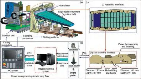
Fig. 1 Finishing machining system of assembly interfaces (1-3—CNC Positioner; 4—NC assistant support).
The assembly interfaces connect large aircraft components,e.g.,vertical tails and rear fuselages.And the finish machining operation for the assembly interfaces is usually performed to guarantee the final assembly quality.The finishing machining system of the assembly interfaces is shown in Fig. 1,which contains some Computer Numerical Control (CNC)positioners, an active clamp unit, a CNC machine tool with On-Machine Measurement (OMM) probe and a laser tracker,as shown in Fig. 1(a) and (b). The CNC positioner is used for the pose adjustment and positioning of the large component(i.e., the vertical tail in Fig. 1). The active clamping unite can apply suitable clamping force on the large component to guarantee the machining stability of the assembly interfaces.Fig.1(c) shows that the assembly interfaces include eight subassembly interfaces,and they are made of 2.5D machining features (e.g., planes and holes). And the milling process for the assembly interfaces generally contains rough- and finishing milling operation, where the rough milling operation is planned to have six Process Steps (PSs), and its Machining Allowance(MA)is 1.8 mm(i.e., 0.3 mm/PS×6). And the finishing milling operation has two PSs, and its MA is 0.4 mm(i.e., 0.2 mm/PS×2).
The assembly interfaces are fixed on the vertical tail, and they belong to a cantilever thin-walled part. Due to the weak rigidity and difficult-to-machine performance of the assembly interfaces, the machining vibration and deformation are commonly occurred during the milling process. Undoubtedly, the machining vibration is one of the main factors affecting milling quality and efficiency, and it can be divided into free vibration, self-induced vibration (especially milling chatter), and forced vibration (especially milling resonance) in terms of vibration generation mechanism.Note that the milling chatter and resonance are directly related to the cutting parameters,and they seriously restrict the machining surface quality of the assembly interfaces. Traditionally, human-machine interaction is used to optimize the cutting parameters of the assembly interfaces in the shop floor. This process relies heavily on work experience, and it is time-consuming and laborintensive.To solve this problem,an in-process adaptive milling method driven by the real-time machining vibration data is proposed in this paper. The method can adaptively optimize cutting parameters between PSs according to the actual machining vibration condition.The contributions of this paper are as follows:(1)A novel time-varying in-operation frequency response function (FRF) estimation method is proposed for the assembly interfaces using the real-time machining vibration data. (2) A 3D Stability Lobe Diagram (3D-SLD) calculation method is optimized with the time-varying in-operation FRF,and it can be used for the chatter prediction during the milling process. (3) An in-process cutting parameter optimization method is proposed based on the 3D-SLD,which can improve the machining quality and efficiency of the assembly interfaces.The remainder of this paper is structured as follows.Section 2 detailed the related work on adaptive machining,milling chatter and resonance.The adaptive milling algorithm is presented in Section 3. In Section 4, an actual milling experiment is carried out to validate the proposed method. Finally, Section 5 concludes this paper and gives future work.
2. Research background
In this section, the adaptive machining method is firstly reviewed.Then,the chatter restraint using SLD based on static FRF, in-operation FRF and time-varying FRF, as well as machining resonance restraint, are respectively discussed.Finally,the problems faced in the milling of assembly interface are detailed.
2.1. Related works
Adaptive machining method. The adaptive machining can be classified into geometric adaptive machining and process adaptive machining.Geometric adaptive machining mainly concentrated on controlling of workpiece geometry. In this method, the machining allowance and geometric error of workpiece need to be primarily paid attention.Within this context,some measurement approaches are employed to calculate the geometric error of the workpiece, such as coordinate machine measurement, on-machine measurement, and laser displacement measurement.After that,error compensation technologies are proposed to improve the geometric machining precision, such as cutting parameters optimizationand tool path optimization. Process adaptive machining can be divided into adaptive control optimization and adaptive control constraint. Adaptive control optimization aims to realize an optimal machining target, such as machining time, material remove rate and machining surface quality.Adaptive control constraint mainly considered to maintain cutting force or cutting power as constant in the machining process.Due to the low stiffness and dynamic properties variation of the assembly interface, the process adaptive milling is a better choice to deal with the severely machining vibration of the assembly interface.
Chatter restraint using static FRF based-SLD.Milling chatter can cause poor surfaces quality and severe tool wear. SLD shows the relationship between spindle speed and axial cutting depth,and it is used to distinguish the stable milling from chatter. So, the cutting parameters can be optimized based on the SLD to restrain the milling chatter.The methods for SLD calculation generally infer to frequency-domain methods (e.g.,Zero-Order Approximation (ZOA) method)and timedomain methods (e.g., the semi-discrete method (SDM) or the full-discrete method(FDM)).ZOA method constructs a chatter stability model based on the zero-order frequency term of the cutting force directivity coefficient matrix. After that, the SLD can be calculated with this model. This method can provide high-level computational efficiency.The SDM and FDM calculate SLD by discretizing the state and delay terms of the delayed differential equations for machining systems,and they can provide high chatter prediction accuracy. The above methods have been validated in real applications, and the key step of these methods is the FRF estimation for the machining system. However, only the static FRF obtained by the impact test is considered.
Chatter restraint using in-operation FRF based-SLD. The impact test is widely used in structure dynamic analyses, and it is performed independently. However, Zaghbani and Sonjmeneemphasized that structural FRF differ under static versus operational conditions, which means that an SLD calculated using a static FRF may be useless during machining.Thus,several kinds of researches have focused on the SLD calculation using in-operation FRF based on the machining vibration data. First, the chatter frequency calculated via fast Fourier transformation (FFT) of machining vibration data is used to reverse the modal parameters, and then, the inoperation FRF of the machining system can be estimated.This method can calculate an in-operation SLD, but required at least two try-cut tests to identify the modal parameters.Alternatively,the SLD is calculated via the analyzing of a large amount of the machining vibration data.The prediction accuracy of the method is determined by the amount of data;thus,more try-cut tests were required.An accurate SLD can be obtained to restrain chatter based on the above methods,however,they are time-consuming and costly.To rapidly calculate the in-operation SLD,the method of operation modal analysis(OMA) is a better choice, which can identify the structure modal frequency and damping ratio based on only machining vibration data.Although stiffness cannot be calculated directly by OMA, several researches estimate the inoperation FRF by combining the OMA with an additional mass or stiffness method, or the combination of OMA with experiment modal analysis.The above in-operation FRF estimation methods are mainly concentrated on the dynamic analyzing of machine tool, and their calculation efficiency is low. Thus, an efficient, in-operation FRF estimation method for the assembly interface is required to calculate the SLD to restrain the chatter.
Chatter restraint using time-varying FRF based-SLD.In theory,the SLD calculated using in-operation FRF is more accurate for chatter prediction. However, the FRF of the workpiece is time-varying due to material removal.To address this issue,Salih et al.studied time-varying FRF of the workpiece by finite element analysis(FEA)and the workpiece mass changing during milling is considered. Based on this method,Budak et al.calculated the in-process SLD of a turbine blade, and optimized the cutting parameters. An in-process SLD calculation model was proposed by Tuysuz and Altintas et al.based on the structure dynamic modification, and the method can update the FRF of a workpiece in frequency and time-domain. Zhang and Yang et al.constructed an in-process dynamic model for large thin-walled parts with substructure synthesis method, and an in-process SLD that considered FRF varying with the cutting tool position variation was calculated. The same as Feng et al.calculated the inprocess SLD considering the process damping. Shi et al.constructed an in-process SLD calculation model from the viewpoint of energy, in which the energy loss with material removal is studied. In short, the above approaches can calculate 3D-SLD with time-varying FRF, and the chatter can be efficiently predicted and controlled during the milling process.However,only the effect of chatter is studied while milling resonance is ignored.
Machining resonance restraint. Machining resonance severely affect machining surface quality of the workpiece,even damages it, especially for the large-scale workpiece. Targeting this problem, Germashev et al.emphasized that the spindle excitation frequency should never be the same as the workpiece modal frequency. Zhang et al.optimized cutting parameters to restrain both chatter and resonance, and the experiment results shown that their method can reduce the workpiece surface location error and surface roughness.Zhang et al.gave a systematic discussion on the chatter and resonance restraint via cutting parameters optimization. Milling resonance significantly compromises machining quality for large-scale parts, and must be avoided.
2.2. Problems faced in the milling for the assembly interfaces
From the above literatures,to improve machining quality and efficiency of the assembly interface, the process adaptive milling can be employed. Furthermore, three methods for SLD calculation are summarized, the first method mainly employed impact test, the second method is driven by the machining vibration data, and the final method is based on the structure dynamic modification theory. The cutting parameters can be optimized based on the SLD to restrain the milling chatter and resonance. However, due the low stiffness and the complex machining condition of the large-scale assembly interface, four problems are faced while the above methods are applied to the assembly interface of vertical tail, as follows:
(1) The impact test can only estimate the static-FRF,and it
is time-consuming for the large-scale workpiece.
(2) The existing machining vibration data-driven methods need at least two try cutting tests to calculate the SLD. It is a cost approach, and the milling of assembly interfaces for the vertical tail may not allow for this operation. More importantly, the dynamics of the thin-walled assembly interface should be primarily considered.
(3) The structure dynamic modification method identifies the time-varying modal parameters of the machining system based on FEA.But the non-ideal machining conditions may be ignored, e.g., clamping deformation,machining deformation. So, it is difficult to construct an accurate time-varying finite element model for the complex machining system of the assembly interface.
(4) Milling resonance significantly reduce surface quality,and it should be avoided meanwhile in the milling.Targeting these problems,this research tries to put forward a novel in-process adaptive milling method for assembly interface driven by the machining vibration data. The method can estimate the time-varying in-operation FRFs of the assembly interface with Finite-Element-Unit-Force (FEUF) methodand optimized STD method (an OMA method). The 3DSLD is calculated with these FRFs,and it can be used to optimize cutting parameters for each PS to reduce milling chatter and resonance in the meantime. The proposed method tries to improve the machining surface quality and material remove rate during the milling process of the assembly interface.Thus,it belongs to process adaptive machining, and defined as inprocess adaptive milling is this paper.
3. In-process adaptive milling for assembly interfaces
Milling chatter and resonance are easily generated when the cutting parameters of assembly interfaces selected inappropriately. Thus, an in-process adaptive milling algorithm is proposed in this section to solve this problem. Note that only one sub-assembly interface is studied to explain the method.
3.1. In-process adaptive milling framework for assembly interface
Taking the time-varying dynamic properties of the assembly interface into consideration, the milling operation of the assembly interface is planned as follows.(1)The whole milling operation is divided into n PSs. (2) The machining vibration data for each PS are separated into m DSs to simulate the material removal of the assembly interface, and each DS represents one milling stage.With this algorithm,the milling operation of the assembly interface contains a total of n×m DSs,shown in Fig. 2.
The machining vibration data in each PScan provide a feedback to adaptively optimize the cutting parameters for the PS. Based on this principle, considering to restrain the milling chatter and resonance, as well as improve the machining quality, an in-process adaptive milling framework is proposed for the assembly interface, shown in Fig. 3. And, the framework is detailed as following 6 steps.
Step 1:The value of n and m are set according to the size of the assembly interface, and the counters i and j are set as 1.Moreover, the cutting parameters (including spindle speed nand axial cutting depth a) for PS(i=1) are conservatively selected.
Step 2:PS(i=1,2,3,...,n),with nand a,is performed to the assembly interface and machining vibration data is collected.The data can be separated into m DSs according to Step 1.
Step 3: The stiffness of the assembly interface is calculated using the FEUF method and the modal parameters for each DS(j=1, 2, 3, ..., m) in PSare identified via optimized STD method based on the machining vibration data. So, the in-operation FRFs for DScan be estimated to construct the time-varying in-operations FRFs for PS.
Step 4:Using the above FRFs,the SLDs for DSare calculated in terms of chatter stability model, and the 3D-SLD for PSis obtained by interpolation of all SLDs. The material removal information is contained into the 3D-SLD.
Step 5: The cutting parameters of the PSare optimized based on the 3D-SLD of PS, while aiming to restrain the milling chatter and resonance, as well as improve machining efficiency. The optimized cutting parameters can be expressed as nand a.
Step 6:If MA-∑a≥0,execute i=i+1,n=n,and a=a, and then, return to Step 2; else a=MA-∑aand the PSis performed until finishing is completed.
Based on the above steps,the in-process cutting parameters of the assembly interface are adaptively optimized between the PSs based on the actual machining vibration condition. Thus,the machining quality and efficiency can be improved with the in-process adaptive milling method.
3.2. 3D-SLD calculations for each process step of the assembly interface
3D-SLD forms the basis of the adaptive milling method.Thus,this section firstly constructs the chatter stability model of the assembly interface. Then, the time-varying in-operation FRFs are estimated based on the machining vibration data, and the SLDs are calculated by substituting the above FRFs into the chatter stability model. Finally, a 3D-SLD is obtained by interpolation of all SLDs. This process is detailed as follows.
3.2.1. Chatter stability model construction
During end-milling of the assembly interface (Fig. 4), the cutting tool is perpendicular to the assembly interface. The axial stiffness of the tool is high but that of the assembly interface is low, so the chatter stability model of the assembly interface must consider the degrees of freedom in three directions. It should be noted that,during the milling of the assembly interface, a five-teeth cutting tool is employed and the radial immersion is 90%. Hence, the chatter prediction accuracy of ZOA method is high and acceptable for this machining condition.More importantly, the adaptive milling process of assembly interface need a high optimization efficiency for cutting parameters.Thus,the stability lobe diagram(SLD)should
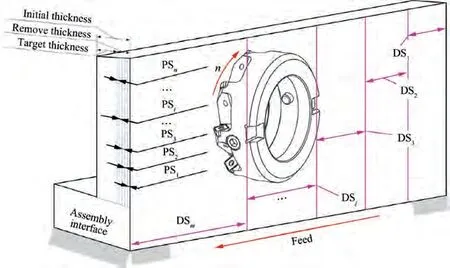
Fig. 2 Initial process planning and data segments of assembly interface.
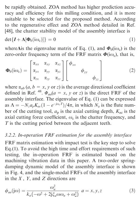
where k,k,k,ω,ω,ωand ξ,ξ,ξare the stiffness,modal frequency, and damping ratio of the assembly interface in the X, Y, and Z directions, respectively.
The stiffness in Eq. (3) can be calculated using the FEUF method.The FEUF method is proposed in the Ref.[47],which is commonly used for structure stiffness calculation, shown in Fig. 5. In this method, a unit force (F=1 N) is acted on the structure and its deformation σ is calculated with FEA. Thus,the stiffness of structure can be obtained by the equation k=F/σ.This process is generally carried out with a commercial FEA software. To identify the in-operation modal frequency and damping ratio, an optimized STD method is employed. The optimized STD method improves modal identification accuracy and reliability by employing the data covariance calculation, modal confidence factor and modal assurance criteria compared with the traditional STD method, and it is detailed as follows. Firstly, two Hankel matrixesare constructed with the machining vibration displacement data of DSin PSas Eq.(4).Then,the data covariance calculation of these two matrixes is done to construct a Toeplitz matrix T for original data preprocessing, shown as Eq.(5). This data preprocessing method can not only extract the free-response vibration of the assembly interface, but also eliminate environmental noise. Thus, the in-operation modal parameters identification accuracy can be improved.
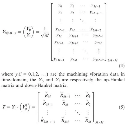
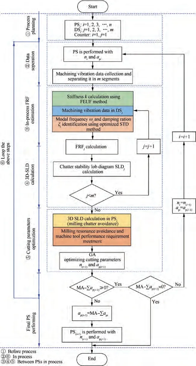
Fig. 3 Proposed workflow of in-process adaptive milling for assembly interface.

where M, C, and K are the modal mass, damping ratio, and modal stiffness matrices of the assembly interface,respectively.x(t) is the displacement vibration response of the assembly interface in X, Y and Z directions under cutting force F(t).Based on the Eq. (5), the free vibration response data in one of the above directions (X or Y or Z), x(t), can be extracted.
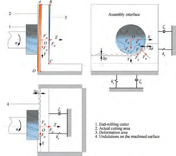
Fig. 4 Milling operation model of assembly interface.
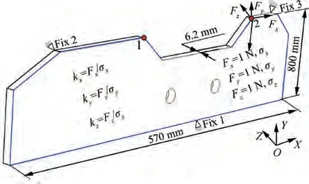
Fig. 5 Schematic diagram of FEUF method.
And this free vibration response is contributed by M-orders modal parameters of the assembly interface,which is written as
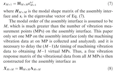
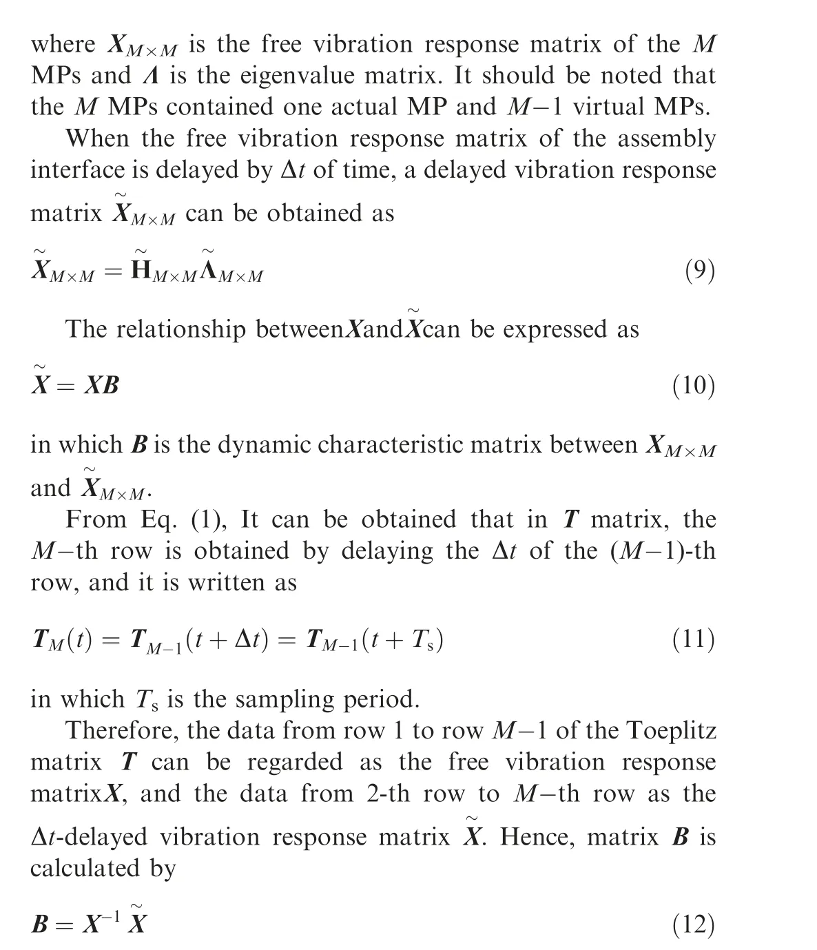
It is obviously that the matrix B is a Heisenberg matrix,which is written as
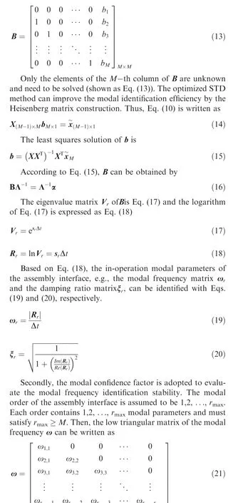
in which ωis the b-th-order model frequency of the assembly interface featuring a total of a orders.
The modal fitting function H is obtained by interpolating the modal order matrix R(R=[1, 2, ..., r]) and ω. The modal confidence factor function h is calculated as the differential of H.h is thus a function of the modal confidence factor κ of modal order r. If the difference between adjacent order modal frequencies is small, the modal frequency of the assembly interface becomes more stable. Thus, the root matrix of h that indicates the similarity of the modal frequencies between adjacent orders is
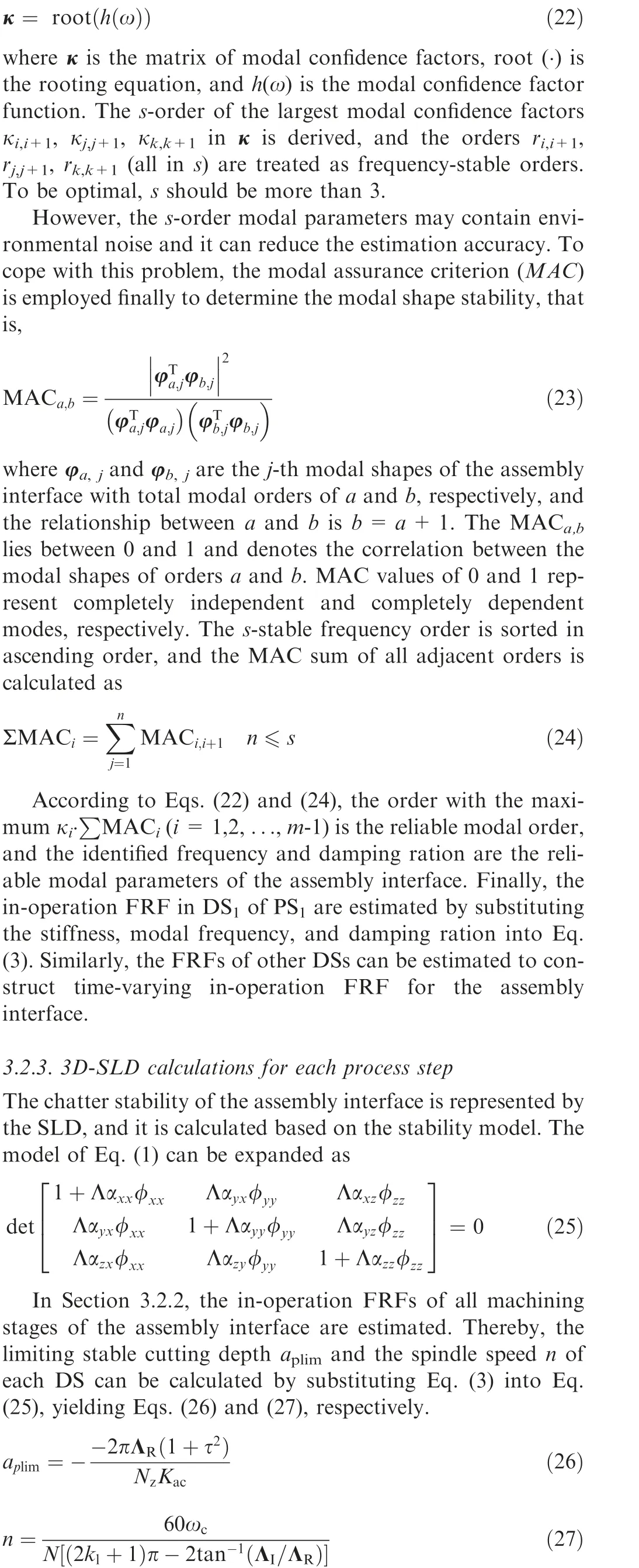
where Λand Λare the real and imaginary eigenvalues,respectively. kis the number of lobes, and τ=Λ/Λ. Given the aand n,the SLDs of all DSs for assembly interface can be calculated,which are used to calculate the 3D-SLD for PSby the approach of interpolation. Moreover, the 3D-SLD calculations for the other PSs are performed similarly. With the 3D-SLD, the following text are concentrated on the cutting parameters adaptively optimization to reduce the milling chatter and resonance.
3.3. Cutting parameters adaptive optimization for the assembly interface
Firstly, to avoid chatter, the limiting cutting depth aand spindle speed n are selected based on the 3D-SLD. It can be expressed as f(a, n)∈f(a, n), in which f(a, n)is the critical stability region defined by 3D-SLD (3D-SLD is calculated in Section 3.2).Next,to avoid milling resonance,the cutting frequency dictated by the spindle speed n should avoid the modal frequency ωof the assembly interface, and it can be expressed as n ≠ω×60/(N×N) (N=1,2, ...). Finally,the spindle torque and power during cutting are constrained by the rated torque and power. Under these requirements,the Material Removal Rate (MRR) of the assembly interface should be improved as much as possible. Thus, Given the above-mentioned constraints and optimization objective, an optimal solution for aand n can be obtained. Note that,the spindle speed with limit axial cutting depth in the SLD is a series of discrete point, and the SLD for each PSis also a series of discrete curve. GA can solve the optimization problem in the discrete space, and it also has strong expansibility,robustness and searching ability which is easily to be combined with other optimization methods to solve the optimization problems. Thus, GA is employed to optimize the cutting parameters in this paper (e.g., the cutting depth, aand the spindle speed, n), as follows.
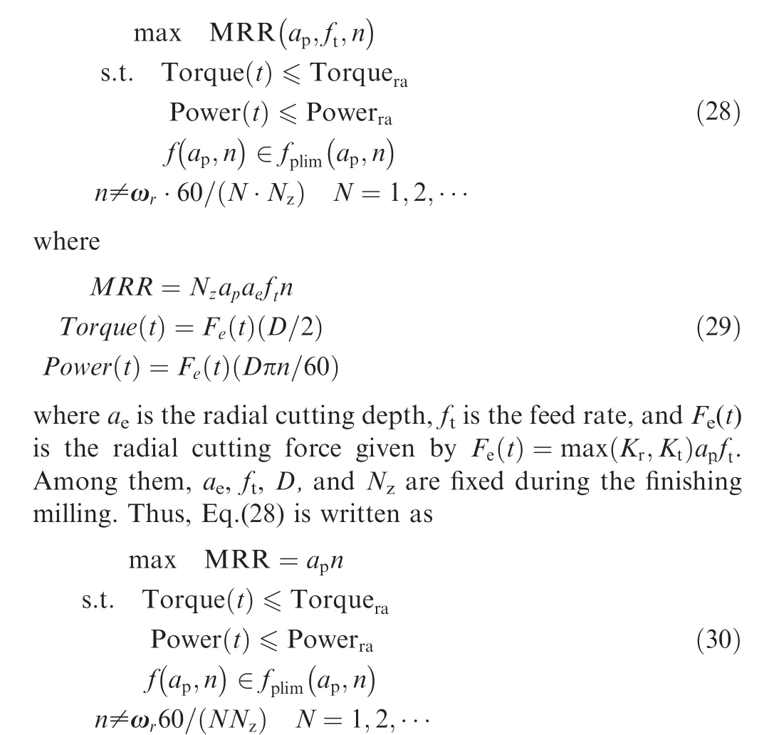
The optimized cutting parameters for PSare given by Eq.(30). When the PSis performed using these parameters, the milling chatter and resonance can be restrained, while the MRR of the assembly interface is improved. The cutting parameters for another PS(i=3, ..., n) can be optimized in the same way.Thus,the real-time machining vibration data in PSare sufficiently considered when the PSis planned and performed during the milling process.
It should be noted that during the milling process of largescale assembly interface, several unexpected factors may change the dynamic of the assembly interface, such as clamping deformation, machining deformation and the variation of the cutting tool. These changed dynamic is defined as the inoperation dynamic properties, and it can be extracted from the machining vibration data of the assembly interface.In this paper, the optimized STD method is proposed to estimate the in-operation modal parameters of the assembly interface based on the machining vibration data.These unexpected factors are considered during the modal identification process. In summary, the proposed data-driven adaptive milling method can not only avoid the impact test, but also consider these unexpected factors.
4. Experimental validation
In this section, a milling experiment for a large-scale assembly interface of vertical tail is adopted to validate the proposed method, shown in Fig. 6(a) and (b). And only the rough milling of one-sub assembly interface is selected to perform the validation.
4.1. Experimental setup
The assembly interface is made of the titanium alloy Ti6Al4V,and its geometric and material parameters are selected and listed in Table 1. The data-processing system included two acceleration sensors (INV9832-50; sensitivity, 99.563 mV/g;frequency bandwidth,20-10000 Hz),a data-acquisition system(INV3062V2; a 24-bit, networked, intelligent data collector),and data processing software (Coninv DASP-V11) (Fig. 6(c)). The machining vibration data is collected at 20 kHz.And a three-axis horizontal machining center is utilized to execute the rough milling,its rated power and torque were 30 kW and 130 N·m, respectively. Furthermore, A five-teeth end mill cutter that is made of cemented carbide is employed, of which diameter, overhang length, helix angle, and material were 50 mm, 200 mm, 55°, respectively.
According to the introduction, rough milling has six PSs,and milling starting from points A to B is regarded as one PS(Fig.6(d)).According to the process knowledge and working experience, the PSis performed with traditional cutting parameters: spindle speed, 152 r/min, axial cutting depth,0.3 mm, and feed rate, 91 mm/min. And the down milling method is adopted.The machining vibration acceleration data of point 2 in X,Y and Z directions are collected while the PSis performed to the assembly interface.As well,the machining vibration displacement can be calculated with the acceleration data. Fig. 7(a)-(f) shows the milling acceleration and displacement data in X, Y, and Z directions of point 2 in 360 s.
4.2. Experimental results
The stiffness in the X, Y, and Z directions of the assembly interface are calculated with the FEUF method, which are k=5.54×10N/m, k=1.73×10N/m, and k=1.85-×10N/m. Note that the milling chatter and resonance are easily triggered in Y and Z direction,it is because the stiffness in the Y and Z directions are low.
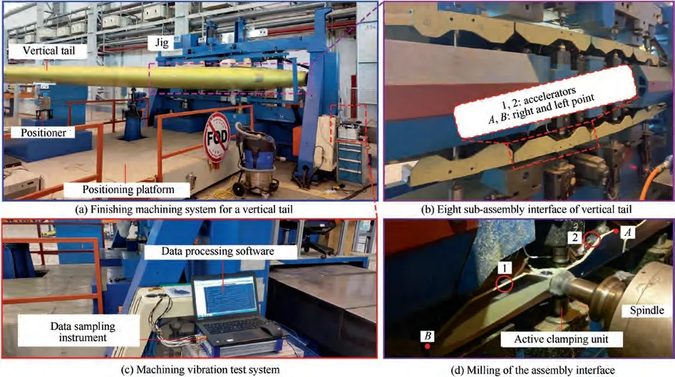
Fig. 6 Experimental setup for adaptive milling of assembly interface.

Table 1 Geometric- and material parameters for assembly interface.
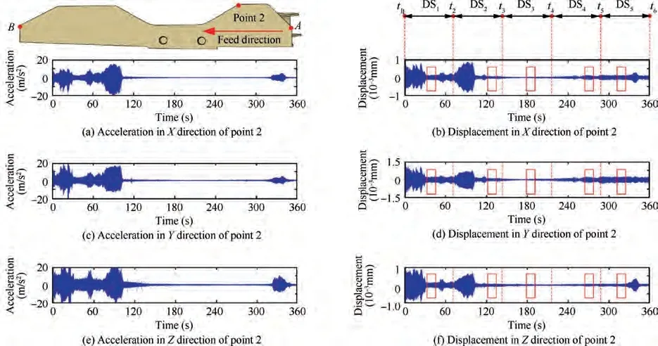
Fig. 7 Machining vibration data at point 2.
The machining vibration data on point 2 of the PSis separated into five DSs,i.e.,DS(i=1,2,3,4,and 5),which represent the five milling stages (Fig. 7(b), (d), (f))). The machining vibration data in DSis taken as an example to identify the in-operation modal parameters of the assembly interface with optimized STD method. To reduce calculation demand while retaining accuracy, the machining vibration data over 10 s of DSis used to construct two 400×400 Hankel matrices with Eq.(4). And then, a 400×400 Toeplize matrix T can be obtained via the data covariance calculation of the above two matrices. After that, the data of rows 1 to 399 and 2 to 400 in T are respectively regarded as the vibration response matrix and the delayed vibration response matrix of the assembly interface. And they are used to calculate the low triangular matrix of modal frequency ω with the Eqs.(19)-(21). Finally, the in-operation modal frequency ωand damping ratio ξfor DSof the assembly interface are reliably identified with modal confidence factors and assurance criteria.It should be noted that only five DSs are separated to explain the modal parameters identification process in this paper, and a more accurate data separation principle should be further studied.
Similarly. Based on the above algorithm, the in-operation modal parameters in other DSs can be identified. Here, due to the space limitation, only the first three-orders modal frequencies and damping ratios of the assembly interface are displayed in Tables 2-4.
The time-varying in-operation FRFs of the assembly interface in the X, Y, and Z directions can be estimated by substituting the stiffness, modal frequency, and damping ratio into Eq.(14). Moreover, the cutting force coefficients are K=1963 MPa, K=646 MPa, and K=778 MPa(Ref.). Thus, the SLDs for DS(i=1-5) of the assembly interface are calculated in terms of the chatter stability model(Eq.(12)), as shown in Fig. 8(a.1)-(a.5). Then, the 3D-SLD is obtained by interpolation of all SLDs shown in Fig. 8(b). It can be obtained that the axial cutting depth decreases with the material removed, which means that the stable machining condition may be changing into unstable during the milling process.
When the 3D-SLD is calculated, the cutting parameters including the cutting depth, aand the spindle speed, n can be optimized. According to the Section 3.3, GA algorithm is employed and shown in Fig. 9. Firstly, the objective function MRR and the optimized variables aand n are given by the Eq.(30), meanwhile, aand n that are coded by 16 bits binary. Then, the initial GA parameters are set as: the initial number of the population is set as P=40,the maximum genetic algebra is set as MAXGEN=500,the mutation rate is set as P=0.3, the crossover rate is set as P=0.4 and the counter gen is set as 0. As the Ti6Al4V alloy is difficult to cut, to ensure the milling safety of the assembly interface, the maximum spindle speed is set to 200 r/min as a GA constraint. Finally, the selection,crossover and mutation are performed for each population,and the cutting parameters are decoding to generate the next population. Loop the above steps until the maximum genetic algebra is reached. While the GA is completed, the optimized cutting parameters are n=192 r/min and a=0.5 mm.

Table 2 Modal frequencies and damping ratios of assembly interface in X direction.

Table 3 Modal frequencies and damping ratios of assembly interface in Y direction.

Table 4 Modal frequencies and damping ratios of assembly interface in Z direction.
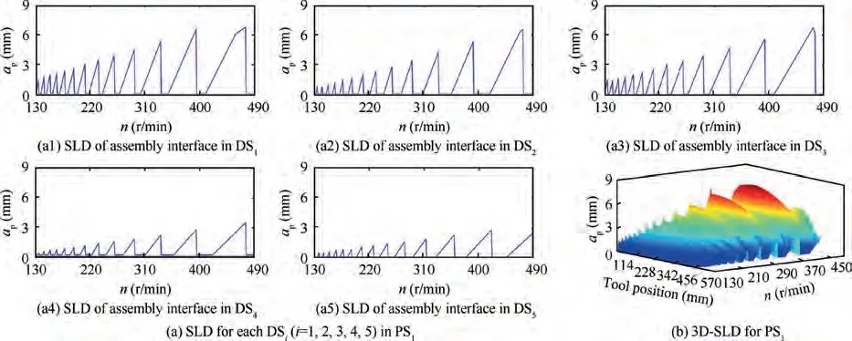
Fig.8 SLDs and 3D-SLD for DSs and PS of assembly interface.
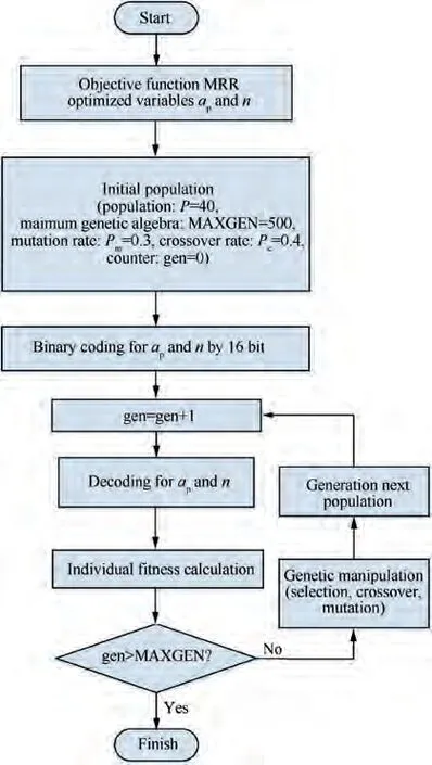
Fig. 9 Cutting parameters optimization with GA method.
To verify the reliability of the optimization, PSis performed using the optimized cutting parameters (n=192 r/min and a=0.5 mm). The machining vibration data in the Z-direction of point 2 is collected,and the frequency spectrum and machining quality before and after optimization are shown in Fig. 10. From which, some experimental results are concluded as follows.
(1) Finishing milling is more stable after optimizing the cutting parameters (Fig. 10(a)). Chatter is generated at a frequency (CF) of 199.9 Hz before the cutting parameters optimization (Fig. 10(b)). Instead, after cutting parameter optimization,the principal frequency components are the Spindle Frequency (SF) and its integral multiples which means that the chatter disappeared(Fig. 10(c)).
(2) Machining quality is improved after cutting parameter optimization. The surface roughness values are improved from Ra 3.2 to Ra 1.6 (Fig. 10(b), (c)).
(3) Only four PSs (0.3 mm×1+0.5 mm×3) are required for rough milling after optimizing the cutting parameters,while six PSs(0.3 mm×6)are required before optimization. Rough milling efficiency is thus improved by 33% when the feed rate is fixed.
Furthermore,the machining vibration data can be collected while the PSis performed, and the 3D-SLD for PScan be calculated. After that the cutting parameters for PScan be optimized.Through this looping process,each PS is performed with the optimized cutting parameters, so that, the in-process adaptive milling for the assembly interface can be realized.
In conclusion, the experimental results illustrate that the machining quality and efficiency of the assembly interface are improved via the proposed adaptive milling method.Thus,it can be obtained that the proposed in-process adaptive milling method is feasible and effective for all the other assembly interfaces of the vertical tail.
5. Conclusions
(1) A new in-process adaptive milling approach driven by the real-time vibration data is proposed for the assembly interface of the vertical tail. The method can adaptively optimize the cutting parameters(spindle speed and axial cutting depth) for each PS according to the actual milling vibration condition. The cutting parameters are dynamically optimized between the adjacent PSs during the milling process to restrain the milling chatter and resonance in the meantime. The experiment results demonstrate that, when the adaptive milling is performed, the assembly interface roughness reduced from R=3.2 μm to 1.6 μm and the machining efficiency improved by 33%.
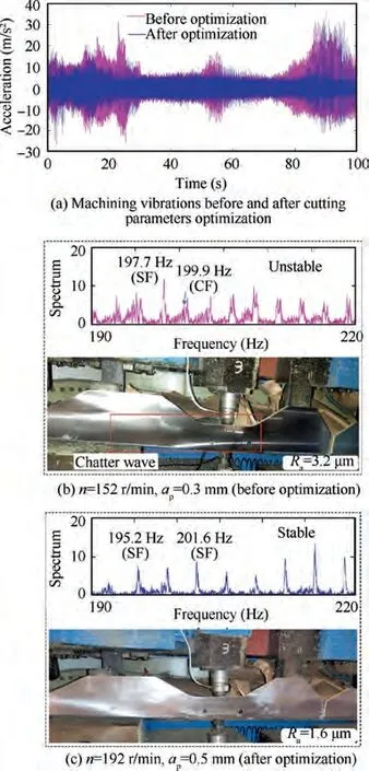
Fig. 10 Machining results display.
(2) The combination of FEUF method and optimized STD method(one of the OMA)is introduced into the milling chatter stability analysis in this paper, which can estimate the time-varying in-operation FRFs of assembly interface with only output/response machining vibration data.This method is suitable for the complex machining system, because the unexpected milling conditions can be effectively considered by the response data analysis,e.g., material removal effect, clamping and machining deformation.
(3) A 3D-SLD calculation method is optimized considering the time-varying in-operation FRF. Theoretically, this method can predict the chatter stability of the assembly interface based on the machining vibration data without the impact test, which is efficient and convenient for application.
(4) The optimized cutting parameters for each PS can be stored and provide some guidance for the milling process planning of the next vertical tail.And the proposed method can also be applied for adaptive milling of largescale thin-walled parts in other fields, e.g., aviation,aerospace, automobiles, and ships.
However, the stiffness variation of the assembly interfaces during the milling process is not included in this method.Thus,a more accurate stiffness modification method is further needed. Besides, maintaining optimal cutting force is also an essential issue for the adaptive milling,which will be our future works.
The authors declare that they have no known competing financial interests or personal relationships that could have appeared to influence the work reported in this paper.
This research is supported by the National Natural Science Foundation of China (No. 51775024) and the MIIT (Ministry of Industry and Information Technology) Key Laboratory of Smart Manufacturing for High-end Aerospace Products Program of China. The authors gratefully acknowledge the help of members of the adaptive milling research group: Wei FAN and Seng YANG, et. al.
