
Interconnected Ni(OH)2 and polyether amine on carbon fiber surface for simultaneously improving interfacial adhesion of epoxy composites and electrochemical properties
2022-04-27 08:23:56QingWUQinqinWANQinliLIUFenWANGXinLIUJinfengZHU
Chinese Journal of Aeronautics 2022年5期
Qing WU, Qinqin WAN, Qinli LIU, Fen WANG, Xin LIU,Jinfeng ZHU
a School of Materials Science and Engineering, Shaanxi Key Laboratory of Green Preparation and Functionalization for Inorganic Materials, Shaanxi University of Science & Technology, Xi’an 710021, China
b Shanghai Composites Science & Technology Co., Ltd., Shanghai 201112, China
KEYWORDS Carbon fiber;Electrochemical properties;Interface/interphase;Polymer-matrix composites;Surface modification
Abstract Interconnected Ni(OH)2 nanoflakes and polyether amine (PEA) were deposited on carbon fiber tows via a facial and effective process of chemical bath deposition and dip coating.Based on this, a win-win benefit of simultaneously improvements in interfacial shear strength (IFSS) of carbon fiber/epoxy composites and the electrochemical activity has been achieved. Compared with CF and CF-Ni(OH)2 composites, the IFSS of CF-Ni(OH)2-PEA/epoxy composite respectively increased 7.9%and 45.4%,which was put down to the covalent bonding of Ni(OH)2-PEA coating with fiber and epoxy matrix,as well as the effective stress transfer by the uniform honeycomb structure of Ni(OH)2.In aqueous KOH electrolyte, the CF-Ni(OH)2-PEA electrode presented the maximum specific capacitance of 689.98F·g-1 at 5 mV·s-1,572.28F·g-1 at a current density of 0.5 A·g-1 due to the strong adhesion of carbon fiber with Ni(OH)2 by PEA, the reservation of the threedimensional hollow honeycomb structure of Ni(OH)2 for easy ion-transport and -NH2 functional groups from PEA for providing more active sites. The excellent performance of CF-Ni(OH)2-PEA reinforcement demonstrates its promising potential for application in high performance composites with integrated structure and function,which shows great advantages in various fields of aerospace,energy, electronics, automobile, civil engineering, sports, etc.
1. Introduction
Carbon fiber reinforced polymer composites (CFRPs) have attracted increasing attention in various fields of aerospace,energy,automobile,civil engineering,etc.,due to their multiple advantages of high strength, weight reduction, high corrosion resistance.However, the virgin surface of carbon fiber is lack of active functional groups and thus leads to the weakness of interfacial adhesion. This further hinders the performance of CFRPs and limits their application in high-tech weapons and national infrastructure.Hence,numerous surface modification methods, including plasma treatment,liquid oxidation,electrochemical oxidation,energy treatment,chemical grafting,sizing treatment,chemical vapor deposition,electrophoretic deposition,layer-by-layerand etc. have been put forward to introduce polar groups, increase surface roughness and improve wetting behavior with polymer matrix. Particularly,combining these approaches with nano-materials by utilizing their unique properties of large surface area and outstanding mechanical properties is more impressive in improving interfacial strength.Nevertheless,the nano-materials’agglomeration, difficulty in raising content of nano-materials and the commonly existed preparation problems of time consuming,high temperature, environmental pollution have to be solved.Therefore, it is imperative to seek nano-materials with welldesigned structure on carbon fiber surface prepared by facile,green and effective strategy for interfacial enhancement.
Three-dimensional (3D) interconnected Ni(OH)sheets are well-suited architecture for supercapacitor electrode because of its large surface structure,electrochemical redox reactions and short diffusion path for ions.As well known,Ni(OH)is a typical two-dimensional material, whose head-to-tail ligation promotes the formation of porous structure and can effectively solve the problems of disordered and agglomerated nanomaterials in surface modification of carbon fiber.Some efforts have tried to use Ni(OH)coating to modify surfaces of PBO fiberand carbon fiber,and indicated the improved interfacial bonding strength of corresponding composites because of the enhanced surface roughness and wettability of fibers.However, these researches are mainly focus on analyzing the interactions of Ni(OH)with matrix, the exploration of Ni(OH)effects on interface between fiber and Ni(OH), and further on the interphase of composites is still lacking.Direct growing Ni(OH)sheets on carbon fiber surface with good adhesion exerts a crucial role in improving interfacial adhesion. Notably,as a great choice for supercapacitor application,the adhesion between Ni(OH)and carbon fiber is equally important because it directly influence the available active surface, electronic conductivity and cyclic stability.To date, Ni(OH)adhered with carbon fibers to improve electrochemical properties is concentrated on carbon cloth,while to support active Ni(OH)on carbon fiber tow is unknown.
Chemical bath deposition (CBD) is conducted by immersing a substrate in aqueous solutions involving precursors under low temperatures,whose essence is similar to the traditional sizing process of carbon fiber.Thus,it is easy to be scaled up at production line of carbon fiber and exhibits characteristics of environmental friendly, effectiveness and low cost. In the present work, CBD was employed to deposit interconnected Ni(OH)nanosheets on the surface of carbon fiber tow. Subsequently, polyether amine (PEA) was added on through fiber impregnation. On one hand, the later coated PEA will not affect the construction of 3D Ni(OH)on fiber surface; on the other hand, PEA contains two terminated amino groups at its flexible chain,which could flow along the porous wall(i.e. vertical Ni(OH)sheets) to the fiber surface and act as a binder to closely integrate fiber, Ni(OH)and matrix.Hopefully, synergistic effect of metal hydroxide and polymer could simultaneously improve interfacial strength of epoxy composites and electrochemical properties of carbon fiber electrode.
2. Material and methods
2.1. Materials
Carbon fibers were purchased from Toray. Epoxy matrix(5228,Beijing Institute of Aeronautical Materials),whose curing cycle is 130 °C for 1 h, 180 °C for 2 h and 190 °C for 3 h.PEA (molecular mass of about 400) was provided by Wuxi Singmen Electronic Materials Co., Ltd. Ammonia solution(25%), potassium persulphate (KSO, 99.5%), Nickel (II)sulphate hexahydrate (NiSO·6HO), nitric acid (HNO,65%-68%), formamide, diiodomethane, acetone and N,NDimethylformamide (DMF) were all purchased from Sinopharm Chemical Reagent Co., Ltd.
2.2. Preparation of CF-Ni(OH)2 and CF-Ni(OH)2-PEA
Prior to deposition,carbon fibers were first refluxed in acetone at 80 °C for 48 h to obtain desized fibers (CF for short). Then CF was oxidized in HNOat 80 °C for 4 h to improve the affinity of fiber with the aqueous plating solution, so that a uniform Ni(OH)coating can be formed on fiber surface.The deposition of Ni(OH)nanoflake onto fiber was realized by CBD, whose detailed process conditions referred to the report of Chen et al.and the resulted fibers were marked for CF-Ni(OH). Subsequently, CF-Ni(OH)was immersed in homogeneous PEA/DMF (0.1 g/100 mL) solution for 15 min and the obtained fibers were signified as CF-Ni(OH)-PEA.The preparation process is portrayed in Fig.1(a).
2.3. Preparation of fiber electrodes
The fiber binder-free electrode was prepared by putting different fibers within two nickel foams (1 cm×2 cm) and pressing with 2 MPa under pressure machine.
2.4. Fabrication of composites
Carbon fiber filament was manually separated and fixed on a concave mold. Then, the resin was dipped onto the filament to form a micro-droplet due to the function of surface tension.After cured in the oven,the single fiber was removed from the mold and glued onto a U-shaped specimen mounting for next test of interfacial shear strength (IFSS).
2.5. Characterizations
The morphologies of different fiber surfaces were identified by scanning electron microscopy (SEM, S-4800, Japan) at 5 kV.The surface structures of different fibers were studied using X-ray diffraction (XRD, Rigaku RINT-2000) with a Cu Kα X-ray source (γ=1.5406 A° ) at 4°/min scanning rate under 40 kV pressure and 40 mA current.Fourier transform infrared spectroscopy (FTIR, Brukey-Vector 22) was employed to characterize the surface groups of fibers, ranging from 400 to 4000 cm. Chemical elements and valence states of different fibers were measured by X-ray photoelectron spectroscopy(XPS, AXIS SUPRA, Kratos, Britain) with a Al Kα X-ray source at 120 W under 10Torr pressure. Contact angle was obtained by using Data-physics’ dynamic contact angle instrument (DCAT21) with 3 mm fiber immersion depth and 0.01 mm/s immersion speed.IFSS(HM410,Japan’s East Wing Industrial Co., Ltd.) was evaluated via micro-debonding method at 0.03 mm/min moving speed and 1/100 gf sensitivity.The electrochemical tests were conducted on electrochemical working station (CHI660E, China) using three-electrode.Fibers were used as working electrode in 3.0 M aqueous KOH electrolyte. Hg/HgO (reference electrode) and Pt foil(1×2 cm,counter electrode)were selected.Cyclic voltammetry (CV) curves were recorded from 0 to 0.65 V at scan rates ranging from 5 to 100 mV·s. The galvanic charge-discharge(GCD) measurements were carried out from -0.1 to 0.4 V at current densities of 0.5, 1, 2, 5 A·g. The IFSS (τ, MPa)was calculated using Eq. (1):where F is the peak pullout force(mN),d is the average diameter of fiber (μm), l is the embedded length of resin droplet(μm). 20 valid tests were used to get the final IFSS value.


Fig.1 Preparation process of CF-Ni(OH)2 and CF-Ni(OH)2-PEA,SEM images of surface morphologies of CF,CF-Ni(OH)2 and CFNi(OH)2-PEA.
The basis of calculation for surface energy, work of adhesion (W, ad representative of adhesion), IFSS and specific capacitance refers to the Appendix A.
3. Results and discussion
3.1. Surface morphology and properties of carbon fiber
Fig. 1(b)-1(f) show the surface appearances of CF, CF-Ni(OH)and CF-Ni(OH)-PEA. Grooves of varying depths along the fiber axis are clearly observed on CF surface(Fig. 1(b)), which is derived from its wet spinning process.CF-Ni(OH)image (Fig. 1(c)) reveals a highly homogeneous covering with hollow honeycomb structure.Higher magnification image(Fig.1(e))indicates that the covering is made up of vertically grown and densely arranged interconnected nanoflakes, which may provide a large surface area and increase the contact points between the carbon fiber and the matrix.For CF-Ni(OH)-PEA, the dip-coating approach not only applies a homogeneous PEA layer to CF-Ni(OH)surface(Fig. 1(d)), but also reserves the hollow honeycomb structure.Moreover, the surface pores become smaller, probably implying the entering of PEA into the spaces among nanoflakes(Fig. 1(f)).
The XRD patterns of CF, CF-Ni(OH)and CF-Ni(OH)-PEA are compared in Fig. 2(a). For CF, there presents four significant diffraction peaks at 26.04°, 30.22°, 43.54° and 51.72°, respectively corresponds to the crystal planes of(002), (210), (100) and (004).Compared with the reported XRD patterns of CF,the CF used in our experiment has narrower and stronger diffraction peaks of (002), (100) and(004), indicating larger grain size and higher degree of graphitization. By analogy to CF, new diffraction peaks at 11.57°,22.68° and 33.40° of CF-Ni(OH)are ascribed to (003), (006)and (101) of Ni(OH)phase (JCPDS-38-0715), indicating the formation of Ni(OH)nanoflakes on fiber surface. After coating PEA, there is no other distinction from CF-Ni(OH),except the decreased intensities of typical diffraction peaks of Ni(OH)due to the incorporation of amorphous structure of PEA.
Functional groups on carbon fibers were analyzed by FTIR, as shown in Fig. 2(b). For CF, the main characteristic peaks at about 3459 cm, 1650 cmand 1042 cmare assigned to the stretching vibrations of -OH, carboxyl and aromatic ether,which are derived from the electrolytic oxidation process during the manufacture of fibers. After Ni(OH)deposition, the peaks at 3640 cmand 3595 cmfor both CF-Ni(OH)and CF-Ni(OH)-PEA are ascribed to the-OH asymmetry stretch vibration in Ni(OH)and the hydrogen bond (O...H-O) formed between free water and Ni-OH.The free -OH vibration appears at 3730 cm. Moreover, CF-Ni(OH)has an additional adsorption peak near 530 cm, which belongs to the stretching vibration of Ni-OH for Ni(OH),while this peak vanishes for CF-Ni(OH)-PEA. Additionally, in terms of CF-Ni(OH)-PEA, a broad peak at 3300-3500 cmis the stretching vibration of N-H, originating from PEA. Meanwhile, a strong absorption peak at 1120 cmis ascribed to the aliphatic ether. All these vibration changes for CF-Ni(OH)-PEA indicate the successful coating of PEA. Interestingly, two features at 1630 cmand 1534 cmof CF-Ni(OH)-PEA are assigned to stretching vibration of C=O, and the combination vibrations of N-H bending and C-N stretching in amide.This indicates the possible reaction between amino groups of PEA and carboxyl groups on fiber surface (generate H-N-C=O).Moreover,this implies that PEA could flow via the hollow honeycomb to the fiber surface and create chemical reactions.
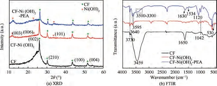
Fig. 2 XRD patterns and FTIR spectra of CF, CF-Ni(OH)2 and CF-Ni(OH)2-PEA.

Fig.3 Wide-scan XPS spectra,O1s spectra of CF,CF-Ni(OH)2 and CF-Ni(OH)2-PEA;Ni2p spectra of CF-Ni(OH)2 and CF-Ni(OH)2-PEA; N1s spectra of CF-Ni(OH)2-PEA.

Table 1 Relative content of elements on fiber surface.
The surface elemental composition and valence state of different fibers were further analyzed by XPS, as presented in Fig.3.The survey spectrum of CF in Fig.3(a)shows elements of carbon, oxygen, nitrogen and silicon. After Ni(OH)deposition (Fig. 3(b)), the typical Ni2p peaks appear and the N1s peak vanishes. Moreover, the content of carbon significantly decreases to 45.28%,while a distinct increment of oxygen content to 42.93%is observed(Table 1).These imply that the fiber surface is covered by Ni(OH)coating.Compared with CF-Ni(OH),the oxygen content on the surface of CF-Ni(OH)-PEA drops to 35.07% (Table 1), accompanied by the increasing content of carbon (55.69%) and nitrogen (1.38%), which is due to the successfully wrapping of PEA over CF-Ni(OH)surface. The high-resolution O1s spectra of CF (Fig. 3(d))exhibits three components of carbonyls (C=O), epoxides(C-O)/hydroxyls (-OH) and carboxyls (O=C-OH), respectively at binding energies 530.3 eV,532.5 eV and 533.2 eV,due to the electrolytic oxidation process during fiber fabrication.For CF-Ni(OH), the O1s spectra (Fig. 3(e)) corroborated the existence of oxygen of the hydroxyls on Ni(OH)at about 531.0 eV.Meanwhile, its Ni2p spectra (Fig. 3(g))display two spin-orbit doubles of Ni2p(855.5 eV) and Ni2p(873.3 eV) along with two shakeup satellites (labeled as ‘‘sat.”) centered at 861.0 eV and 879.1 eV,suggesting the existence of+2 oxidation state of Ni species in CF-Ni(OH)and matching well with XRD results. The O1s, Ni2p and N1s spectra of CF-Ni(OH)-PEA are respectively presented in Fig. 3(f), Fig. 3(h) and Fig. 3(i). Apart from the decreased peak content of -OH on Ni(OH)(from 70.35%of CF-Ni(OH)to 57.29%),a new ether(C-O-C)peak appears at about 532.2 eV (Fig. 3(f)). Moreover, the peak at 400.9 eV in Fig. 3(i) belongs to the amide groups (-N-C=O), again indicating the reactions between PEA and fiber surface.This further suggests that the PEA could touch and react with the fiber surface.
3.2. Surface energy, wettability and work of adhesion analysis
The contact angles of fibers with water,formamide and diiodomethane are shown in Fig.A1(Appendix A).A clearly downward trend in contact angles of polar water for CF, CF-Ni(OH)and CF-Ni(OH)-PEA are observed. The surface energies (γ) of fibers are displayed in Fig. 4(a). Surface energy increases from 19.97 mJ/mto 23.98 mJ/mafter the deposition of Ni(OH), which was mainly from the contribution of dispersion component (γ, d representative of dispersion) due to the hollow honeycomb structure. After further covering PEA, the surface energy grows up to 29.08 mJ/mowing to the improved polar component (γ, p representative of polar)by amino terminated groups. Generally, higher surface energy of fiber benefits next wetting with polar matrix, and this variation is also observed in Fig. 4(b) that the contact angle present a gradual decreasing trend.
For the interphase of CF-Ni(OH)/epoxy, there exists two interfaces, respectively between CF and Ni(OH), between Ni(OH)and epoxy. While for CF-Ni(OH)-PEA composite, its interphase region consists of three interfaces, that is between CF and Ni(OH)-PEA, between Ni(OH)-PEA and epoxy,and between Ni(OH)and PEA.To better evaluate the adhesion effects of surface coating on CF and matrix,series Wvalues of interfaces are summarized in Table 2.Wbetween CF and Ni(OH)-PEA coating are 48 mJ/m, higher than 43.75 mJ/mbetween CF and Ni(OH), indicating that there needs more energy to separate CF with Ni(OH)-PEA.This could be caused by the chemical interactions of infiltrated PEA with fiber surface that enhance their interface adhesion.However,these two Wvalues are both inferior to that between Ni(OH)and PEA(52.49 mJ/m),probably because of abundant hydrogen bonds between-OH of Ni(OH)and-NHof PEA,and the mechanical bite as well.Moreover,this in turn implies that PEA flows in the vicinity of fiber surface is helpful for improving linking fiber with Ni(OH).For the Wof fibers with matrix,CF <-CF-Ni(OH)<CF-Ni(OH)-PEA, which well consists with the variation of contact angle in Fig. 4(b) and indicates the strongest interface between CF-Ni(OH)-PEA and matrix. In addition,Wvalues between CF and surface coatings are both obviously lower than those of corresponding surface coatings with matrix (i.e. 43.75 mJ/m<59.16 mJ/m;48.00 mJ/m<62.00 mJ/m),which suggests that the interfaces between surface coatings and matrix are stronger than the interfaces between CF and surface coatings. To sum up, Ni(OH)-PEA reveals stronger interfacial adhesion with both CF and epoxy matrix.
3.3. Interfacial shear strength
Fig. 5(a) presents the IFSSs of fiber/epoxy composites. The IFSS of CF-Ni(OH)composites declines 25.8% to 51.8 MPa, as compared with CF/epoxy. In Fig. 5(b), there is a small amount of epoxy fragments on CF surface, however,the de-bonding surface of CF-Ni(OH)is neat without any epoxy residual (Fig. 5(c)), directly proving the IFSS results.What’s noteworthy is that the interface between Ni(OH)and epoxy matrix still keeps intact(red dotted ellipse),indicating the weak interface between CF and Ni(OH). Although Wbetween CF-Ni(OH)and matrix (59.16 mJ/m) is higher than that between CF and matrix (53.62 mJ/m), the Wbetween CF and Ni(OH)is much lower(43.75 mJ/m),which is detrimental to the interfacial adhesion of CF-Ni(OH)/epoxy composites. This result is totally different from the reported work that Ni(OH)/NiOOH deposition layer could give 46.3% raise to the IFSS of PBO composites.This may be due to that PBO surface is smooth, the addition of Ni(OH)/NiOOH coating dramatically increases the mechanical interlocking between fiber and matrix. While in our work,there are already many grooves in different shades on CF surface(Fig.1(b)),mechanical bite of Ni(OH)is not so effective.After adding PEA, CF-Ni(OH)-PEA/epoxy results a higher IFSS of 75.3 MPa, with 7.9% and 45.4% improvements than CF and CF-Ni(OH)composites. The reasons for the increase can be ascribed to the following three aspects: (1) Previous FTIR and XPS results indicate that PEA could closely contact and react with CF,and thus improve the interface between CF and Ni(OH)-PEA coating, avoiding the existence of weak interface. (2) The improved surface energy of CF-Ni(OH)-PEA promote its wetting with epoxy matrix. On one side, this facilitates the infiltration of matrix into the hollow Ni(OH),which increases the anchoring effect of matrix with Ni(OH);on the other hand, molecule entanglement and chemical reaction between polyether amine and epoxy matrix is built,which bridges the coating with fiber and matrix. In Fig. 5(d), abundant epoxy debris adhered on CF-Ni(OH)-PEA surface gives the direct evidence. (3) Under the premise that the previous two factors exist simultaneously, the uniformly wrapped CF of Ni(OH)with honeycomb structure facilitate the stress transfer through the interphase, effectively avoiding stress concentration.

Fig. 4 Surface energy of carbon fibers and contact angle between fibers and matrix.
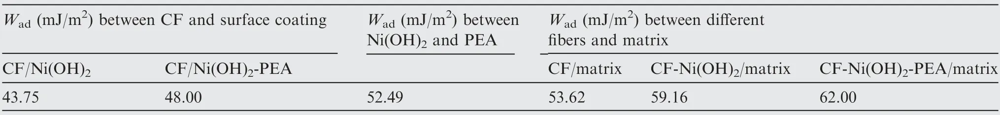
Table 2 Wad between CF and surface coating, between Ni(OH)2 and PEA, between different fibers and matrix.

Fig.5 IFSSs of different fiber/5228 composites;Fiber surface morphologies after de-bonding:CF,CF-Ni(OH)2 and CF-Ni(OH)2-PEA.
3.4. Electrochemical properties
CV curves of CF, CF-Ni(OH)and CF-Ni(OH)-PEA at a scan rate of 20 mV·sare given in Fig. 6 (a). CF-Ni(OH)-PEA has the largest curve area and current response, suggesting the obviously improved specific capacitance.The rate capability of CF-Ni(OH)-PEA(5-100 mV·s)presented in Fig.6(b)basically possesses symmetrical shapes,and the shapes vary little under different scanning rates, implying the good reversibility and high rate capability.Moreover,the potentials of anodic and cathodic peaks separately move to positive and negative directions, resulting in an increase in peak potential difference. The electrochemical polarization of active substances on the electrode and the concentration polarization of the electrolyte occur under a large scanning speed, which reduces the utilization rate of active sites.Thus, the higher potential difference means the worse rate performance.In Fig. 6(c), the highest specific capacitance of CF-Ni(OH)-PEA is up to 689.98F·g, then the value gradually declines with increasing scanning rate, but the specific capacitance is consistently above those of CF and CF-Ni(OH). The GCD measurements were also conducted to further confirm the electrochemical properties of CF-Ni(OH)-PEA. At a constant current density of 0.5 A·g(Fig. 6(d)), CF-Ni(OH)-PEA has the longest charge and discharge time, indicating the best electrochemical capability. The GCD curves of CF-Ni(OH)-PEA at different current density (0.5-5 A·g) are displayed in Fig. 6(e) to evaluate its energy storage ability. As the function of current density, the specific capacitances are plotted in Fig. 6(e). The maximum specific capacitance of CF-Ni(OH)-PEA at 0.5 A·gis 572.28F·g,2.3 and 7.3 times higher than those of 244.81F·gand 78.92F·gat 0.5 A·gfor the CFNi(OH)and CF. When the current density further increases to 5 A·g,the specific capacitance of CF-Ni(OH)-PEA drops to 392.24F·g. However, the capacitance was still exhibited 68.5% maintenance, higher than 50.8% of CF-Ni(OH), indicating the high rate capability under high current density.

Fig. 6 CV curves of CF, CF-Ni(OH)2 and CF-Ni(OH)2-PEA at 20 mV·s-1; CV curves of CF-Ni(OH)2-PEA at scanning rates ranging from 5 to 100 mV·s-1;Specific capacitance as the function of scanning rate;GCD curves of CF,CF-Ni(OH)2 and CF-Ni(OH)2-PEA at 0.5 A·g-1; GCD curves of CF-Ni(OH)2-PEA at current density from 0.5 to 5 A·g-1; Specific capacitance as the function of current density.
In comparison with CF,the higher electrochemical properties of CF-Ni(OH)and CF-Ni(OH)-PEA could be contributed to the redox reactions and the continuous ion diffusion pathway by the 3D hollow honeycomb structure of Ni(OH)By contrast with CF-Ni(OH), PEA acts as a role to closely connect Ni(OH)with CF, which reinforces the stability of Ni(OH)structure during charge/discharge cycles and makes full use of cross-linked structure of Ni(OH)for easy ion-transport.Moreover, micro-conductive channels could be formed within Ni(OH)-PEA coating, which accelerates the rapid adsorption/desorption process of ions on the surface where electrode touches electrolyte to complete the energy storage and release. In addition, the C-NHfunctional groups from PEA may provide more active sites to improve the specific capacitance.Therefore, CF-Ni(OH)-PEA exhibits the maximum specific capacitance and stability.
4. Conclusions
In this work, interconnected Ni(OH)and PEA were directly deposited on carbon fiber surface via CBD and dipping approaches to simultaneously improve the interfacial bonding strength of epoxy composites and electrochemical properties of carbon fiber electrode. By contrast with CF and CF-Ni(OH)composites, the IFSS of CF-Ni(OH)-PEA composite increased 7.9% and 45.4%, due to the covalent bonding of Ni(OH)-PEA coating with fiber and epoxy matrix and the honeycomb structure of Ni(OH)that effectively transfers stress. In aqueous KOH electrolyte, the as prepared CF-Ni(OH)-PEA electrode exhibited specific capacitances of 689.98F·gat 5 mV·s, 572.28F·gat 0.5 A·g, which are both significantly higher than those of CF and CF-Ni(OH)electrodes. The increase in specific capacitance can be ascribed to the strong adhesion of CF with Ni(OH), 3D hollow honeycomb structure of Ni(OH)for easy ion-transport, -NHfunctional groups from PEA for providing more active sites. The present study demonstrates the synergistic role of metal hydroxide and polymer in improving interfacial properties of composites and electrochemical properties of carbon fiber electrode,which may provide an effective approach to achieve high performance composites with integrated structure and function. Such composites will show its advantages in aerospace, energy, electronics, etc.
The authors declare that they have no known competing financial interests or personal relationships that could have appeared to influence the work reported in this paper.
The authors acknowledge Chengwei WANG and Yujia XUE at Shaanxi University of Science & Technology, for their help with preparation and testing of electrochemical samples. This work was supported by the National Natural Science Foundation of China(No.51603169),Natural Science Basic Research Plan in Shaanxi Province of China(No.2017JQ5050)and Natural Science Foundation of Shaanxi University of Science &Technology (No. 2016QNBJ-12).
Appendix A. 1 1. Measurements


Fig. A1 CAs of different fibers with water, formamide and diiodomethane.