DFCluster: An efficient algorithm to mine maximal differential biclusters for single pilot operations task synthesis safety analysis
Yong CHEN, Yue LUO, Mio WANG,*, Kelin ZHONG, Gng XIAO,Guoqing WANG
a School of Aeronautics and Astronautics, Shanghai Jiao Tong University, Shanghai 200240, China
b Commercial Aircraft Corporation of China, Ltd., Shanghai 200436, China
c China COMAC Shanghai Aircraft Design and Research Institute, Shanghai 201210, China
KEYWORDS Differential bicluster;Flight scenario design;Safety analysis;Single pilot operations;Task synthesis
Abstract With the continuous advancement of the avionics system,crew members are correspondingly reduced,and Single Pilot Operations(SPO)has attracted widespread attention from scholars.To meet the flight requirements in SPO mode,it is necessary to further strengthen air-ground coordination system integration,but at the same time,there will be some safety issues caused by resource integration, function fusion, and task synthesis. Aimed at the safety problems caused by task synthesis, an efficient differential bicluster mining algorithm--DFCluster algorithm is proposed in this paper to discover potential hazardous elements or propagation mechanisms through mining the resource-function matrixes. To mine efficiently, several pruning techniques are designed for generating maximal biclusters without candidate maintenance. The experimental results show that the DFCluster algorithm is more efficient than the existing differential biclustering algorithms under different scales of artificial datasets and public datasets. Then, a typical flight scenario is designed based on SPO air-ground collaborative system architecture, and combined with our proposed DFCluster algorithm for task synthesis safety analysis. Based on the mining results, the SPO airground collaborative system architecture is modified, which ultimately improves the safety of the SPO system.
1. Introduction
Single Pilot Operations (SPO) is an important research direction in the development of modern aviation technology.It can effectively reduce the cost of pilots, relieve the pressure due to the shortage of pilots, decrease the space and size of the cockpit, cut down the configuration of the cockpit display system,and eliminate decision-making conflicts between pilots,which is of great significance.
With the continuous improvement of the comprehensive capabilities of the avionics system, the crew of civil airliners has evolved from a five-person operating mode which consists of a captain,a first officer,a flight engineer,a navigator,and a radio operator to the dual-pilot operating mode which contains only captain and first officer, but the dual-pilot mode,as the control and operating mode of the aircraft, which includes piloting operations, environmental monitoring, interactive driving,decision making and substitute for the incapacitated pilot, has never been changed since then. However, the SPO mode has completely changed the traditional dual-pilot mode, and in the absence of another captain’s ability to complement each other, interactive decision-making and status confirmation, safety issue is the first problem faced by SPO.
To make SPO mode reach the same level as the current dual-pilot operating mode in terms of driving efficiency and quality, the capabilities of the avionics system need to be enhanced.Therefore,in SPO mode,for meeting flight requirements,it needs to further strengthen system integration including task synthesis, function fusion, and resource integration,and the high level of system integration will improve efficiency but also introduce safety issues that cannot be underestimated.With the expansion of system integration scope and the increase of integrated functions, the task organizing mode becomes complicated, which causes difficulties to the system safety analysis and evaluation. In particular, the problems of multi-capability organization, multi-process organization,and multi-task organization caused by task synthesis will make it difficult to determine the system fault status and diagnose the fault composition.
The safety models of traditional safety analysis including Fault Tree Analysis(FTA),Failure Modes and Effects Analysis (FMEA), and Hazard and Operability Studies (HAZOPS)are constructed manually based on engineering experience.To meet the flight requirements in SPO mode,it is necessary to further strengthen air-ground coordination system integration,but at the same time,there will be some safety issues caused by system integration,mainly including the following aspects:(A)SPO air-ground collaborative physical resource integration will not only bring efficiency improvement but also make resources no longer closed. Resources are related in terms of professional capability, resource operation and resource organization, with real-time dynamic characteristics, which brings safety issues such as system state uncertainty and fault propagation. (B) Function fusion in SPO mode brings about the improvement of information quality, and it is also faced with the safety problem that complex functional cross-linking relationship makes it difficult to find the root cause. (C) SPO airground cooperative task synthesis is accompanied by the problems of multi-capability organization, multi-process organization, and multi-task organization, which will make it difficult to determine the system fault status and diagnose the fault composition.
Therefore, the SPO avionics system is more sophisticated and complex, and the classic analysis methods (such as FTA and FMEA) become incompetent to provide dependable results. Recently, Model-Based Safety Analysis (MBSA)has been developed and adopted successfully in diverse fields.Besides, to solve the inconsistency between the system architecture design model and the safety analysis model,MBSA is applied in this paper. To cope with the increasing number and complexity of system failure modes in the context of task synthesis, data mining can be applied to assist safety analysis of system synthesis.Some bicluster mining algorithms have been proposed,such as the DoCluster algorithmfor discrete data and DeCluster algorithmfor real-valued data to analyze the safety problems caused by task synthesis,but they are limited to mining and analyzing the single task, and the mining results are not particularly good.
In this paper, we propose an improved DFCluster algorithm for mining the function-resource matrix of two different tasks, and it could find out which resources and functions can meet the needs while the two tasks are executed at the same time, and which resources and functions need to be accessed multiple times to support the two tasks, thus supporting SPO safety analysis.In order to mine efficiently,we design several pruning techniques for generating maximal biclusters without candidate maintenance. The contributions of the proposed DFCluster algorithm which distinguish from those of the existing differential biclustering algorithms are summarized as follows:
(1) The new differential function-resource biclusters definition is proposed to discover potential hazardous elements or propagation mechanisms for task synthesis safety analysis.
(2) The differential weighted undirected relational graph is used to store raw data instead of the double-checking method to improve algorithm efficiency.
(3) DFCluster algorithm adopts several pruning strategies for mining maximal differential function-resource biclusters without candidate maintenance.
The remaining sections of this paper are organized as follows. Section 2 presents a brief description of Single Pilot Operations (SPO) for commercial aircraft and SPO system architecture decomposition. Section 3 describes our proposed DFCluster algorithm in detail. Section 4 compares the proposed algorithm with the existing algorithms in mining efficiency and results and designs a typical flight scenario to perform model-based task synthesis safety analysis. Conclusions are drawn in the final section.
2. Single pilot operations for commercial aircraft
2.1. SPO Air-ground collaborative architecture
The main feature of SPO mode which is different from the dual-pilot mode is that it is based on the air-ground collaborative architecture, which includes on-board pilot system, airborne automation system, and ground operator system, as shown in Fig. 1.
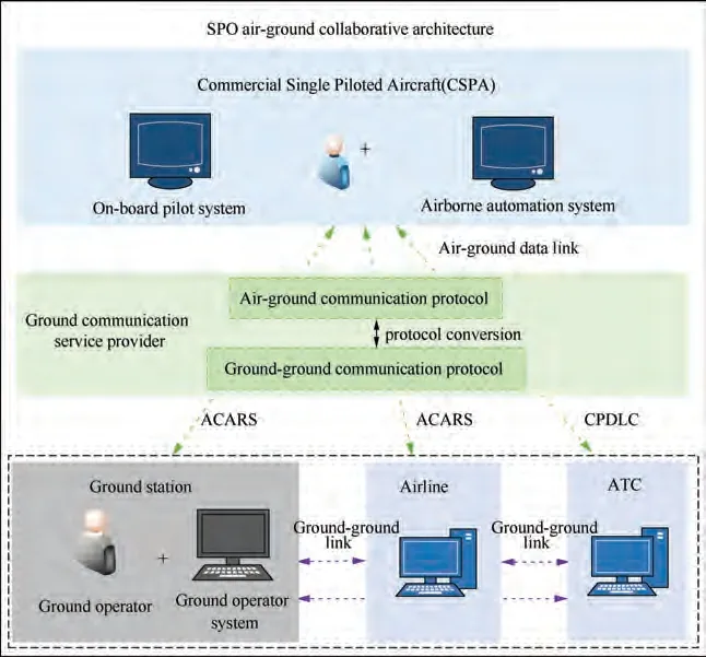
Fig. 1 SPO air-ground collaborative architecture.
The onboard pilot system, which mainly includes flight management system,airborne surveillance system,cockpit display system, airborne communication system, and other airborne avionics systems, is used to assist the onboard pilot to complete flight piloting and flight organization.These avionics systems will be retained and further integrated into the Commercial Single Piloted Aircraft (CSPA). The Flight Management System (FMS) assists the onboard pilot to complete flight planning and navigation. The airborne surveillance system and cockpit display system monitor the airspace environment and display flight status information.The airborne communication system supports the onboard pilot to communicate with the ground operator through Aircraft Addressing and Reporting System (ACARS) and ATC through Controller Pilot Data Link Communications (CPDLC) in real time to achieve collaborative decision-making. As shown in Fig. 2,the onboard pilot system not only supports the pilot’s control of CSPA,but also supports the synchronization of flight information to the airborne automation system, and completes the piloting control according to the control instructions forwarded by the airborne automation system.
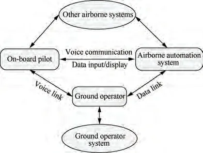
Fig. 2 Cross-linking diagram of SPO air-ground collaborative system.
The airborne automation system includes communication management module, flight environment surveillance module,flight management module, cognitive human-machine interface module,and function allocation module.The communication management module manages the command,control,and communication functions of the data link. The flight environment surveillance module makes fusion decision-making based on the flight environment information collected by airborne equipment. The flight management module performs route optimization and trajectory organization. The cognitive human-machine interface module monitors the capability status of the single pilot in real time, and the function allocation module reasonably allocates the tasks that need a single pilot,ground operator, and automation systems to handle based on the current mission requirements. The airborne automation system can ensure that in SPO mode, compared with the current dual-pilot mode, the workload of the single pilot will not increase,and in case that the on-board pilot is unable to fly the aircraft normally, the airborne automation system can also support the ground operator to control the aircraft. In short,the airborne automation system can reduce the workload of the single pilot, reduce the complexity of the cockpit, increase surveillance capability, and facilitate air-ground coordination and information sharing. As shown in Fig. 2, the airborne automation system is directly controlled by the single pilot,and can also be controlled by the ground operator’s instructions to complete the equipment organization and control of CSPA with the help of other airborne systems.
The ground operator system communicates and synchronizes data with the onboard pilot system through the airground data link to complete monitoring assistance or remote control in different piloting modes. The airline ground operator in SPO mode is different from the airline dispatcher in dual-pilot mode, not only does he need to complete the dispatch work,but also needs to assist the single pilot to complete a safe flight based on the physical condition and piloting specifications of the onboard pilot. And the ground operator can pilot the aircraft remotely as a‘co-pilot’to ensure flight safety when the onboard pilot is in an abnormal physical state.
2.2. Free flight during a land-based cruise in SPO mode
In SPO mode, aircraft also needs to go through the phases of surface operation, take-off, cruise, descent, approach, and landing to complete a flight. Here we choose a land-based cruise for analysis.
In the long-endurance land-based cruise, airspace traffic and meteorological conditions are constantly changing. With the continuous improvement of CSPA’s airborne equipment,the onboard pilot can directly and accurately perceive the current airspace status in real time,while the ATC’s perception of the airspace operating status is obtained through the data sent from aircraft, and due to the delay of transmission link, the real-time perception of ATC is far inferior to that of the pilot on board.Especially in some emergency handling processes or under harsh operating conditions, the information delay of ATC may bring serious consequences. Hence, in face of the complex and dynamic airspace environment, it is necessary to establish coordination among the single pilot,ground operator, and ATC to realize the free flight oriented toward the pilot’s intention. Free flight means that in the airspace authorized by ATC, with ATC’s permission, the pilot can independently construct or adjust a flight segment according to airspace traffic environment and meteorological conditions.
Based on Flight Management System(FMS),Performance-Based Navigation (PBN) and monitoring of the current flight status, and real-time perception of the airspace environment through Automatic Dependent Surveillance-Broadcast (ADSB),the on-board pilot can determine flight sector composition,flight path organization, flight path prediction, flight path guidance, and flight interval constraints. After negotiation and interaction with the onboard pilot, the ground operator can issue a free flight request to ATC. ATC analyzes the airspace environment,delineates the airspace range and operating time of free flight based on the monitoring and communication capabilities of the airspace aircraft, clarifies the minimum safety interval requirements,and finally sends back a free flight permit.As shown in Fig.3,in the airspace authorized by ATC,the aircraft detects the weather threat ahead, and then builds an autonomous route to avoid hazardous weather. It obtains airspace traffic information through ADS-B and TIS-B, analyzes the flight status and intentions of other aircraft in the airspace through FMS, and establishes collision detection that violates minimum isolation. Once a flight conflict is found,FMS automatically generates an alert and provides the pilot with several flight path modification methods to resolve potential conflicts.The onboard pilot cooperates with the conflicting aircraft through voice communication,and the conflict resolution process is completed by them autonomously. ATC monitors and manages the traffic information in the airspace based on the flight status and intention information sent from Automatic Dependent Surveillance-Contract (ADS-C), combined with the monitoring information provided by ground radar.
2.3.Surveillance requirements during a land-based cruise in SPO mode
Flight process surveillance is an important guarantee for the effectiveness and safety of a land-based cruise. For the longendurance land-based cruise, flight process surveillance provides real-time flight and operating status monitoring, which is the basis for flight process organization and management.It is through the construction of a combined surveillance mode of ground radar,ADS-B,ADS-C,airborne weather radar,and Traffic Collision Avoidance System (TCAS) to support flight trajectory prediction, flight status perception, route weather detection, and collision avoidance warning. In SPO mode,because the ground operator cannot observe the airspace environment outside CSPA through the porthole, in order to reduce the loss of visual information caused by the ground operator not being onboard, the relevant airspace data will be transmitted down to the ground station through the airground data link.Then,the station visualizes the data through ground simulation software so that ground operators can monitor the flight process and make coordinated decisions.
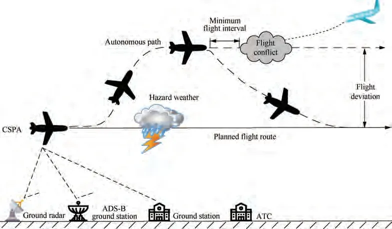
Fig. 3 Free flight during land-based cruise in SPO mode.
Combined with the characteristics of free flight during the land-based cruise phase in SPO mode mentioned in Section 2.2,the flight process surveillance functionmainly includes the visual acquisition of other traffic for enhancement,traffic situational awareness, weather status awareness, conflict situational awareness, autonomous flight interval management,and collision situational awareness.
2.3.1. Visual acquisition of other traffic for enhancement
Visual acquisition of other traffic for enhancement refers to the establishment and enhancement of the pilot’s visual perception ability of the front-end traffic of CSPA.The visual acquisition is based on Automatic Dependent Surveillance-Broadcast(ADS-B) and Cockpit Display of Traffic Information (CDTI)to establish the current traffic environment and provide monitoring and avoidance.For aircraft that are not equipped with ADS-B, relevant information will be obtained through Traffic Information Service-Broadcast (TIS-B). The ground station is also equipped with a traffic information display module to visualize the data received through air-ground data link, so that ground operators can complete flight monitoring and coordinated decision-making.
2.3.2. Traffic situational awareness
2.3.3. Weather status awareness
Weather status perception provides current weather conditions of the flight route and establishes traffic status, route conflict,and threat status in a graphical way. The meteorological images are displayed to show meteorological conditions,types of meteorological hazards (such as thunderstorms or turbulence),and their position and severity to support pilots to construct User-Preferred Trajectory (UPT).
2.3.4. Conflict situational awareness
Conflict situational awareness is based on enhanced traffic visual perception, and according to current traffic situational awareness, based on the planned flight route and navigation path, through flight trajectory calculation and prediction, the current and potential flight conflicts can be identified. ADSB IN establishes the current traffic environment perception,RNP navigation provides flight guidance paths, FMS system calculates and predicts flight trajectory, and airborne surveillance system establishes Conflict Detection Zone (CDZ) and finally completes the conflict situational awareness. The airborne surveillance system establishes flight conflict warning which provides Advisory, Caution, and Warning according to conflict levels.
2.3.5. Autonomous flight interval management
Autonomous flight interval management is a requirement for land-based cruise management of next-generation aircraft. It means that under the authorization of ATC, the aircraft can autonomously complete the management of flight intervals to prevent and resolve flight conflicts. The single-pilot builds traffic situational awareness and recognizes flight conflicts in the surrounding airspace with the support of advanced airborne equipment, which is shared with the ground operator,and the ground operator issues a request for autonomous flight interval management to ATC. Based on the flight status sent from aircraft in the airspace and the capabilities of their ADS-B, ATC provides autonomous flight interval management permits, notifies conflicting aircraft, and sends flight interval constraints to the ground operator and the requesting aircraft respectively through the ground-ground communication network and CPDLC. FMS receives the permit and constraints, and the single pilot and ground operators carry out air-ground coordinated decision-making and complete autonomous flight interval management.
2.3.6. Collision situational awareness (with TAs & RAs)
No wonder the shoemaker becomes wealthy with so many pairs of shoes to sell so quickly! No doubt the elves can easily make 512 pairs of shoes just as easily as 2 since they are magical beings
Collision situational awareness is based on traffic situational awareness. It establishes traffic Threat Advisory (TA), detects traffic information in traffic alert areas, identifies and tracks potential threatening aircraft, and provides caution displays through CDTI. When the threatening aircraft enters the air Collision Avoidance Zone(CAZ),the collision avoidance Resolution Advisory (RA) is established to remind the pilot to take the maneuvering process to solve the currently discovered collision threat.Collision situational awareness establishes TA and RA based on ADS-B and provides display and voice warnings through CDTI.ADS-B supports to establish the collision avoidance process, provides horizontal, vertical, and speed adjustments, and displays the state and parameters of the maneuvering process through CDTI.
2.4. SPO system architecture decomposition
It is known that the avionics system in SPO mode is more advanced and more integrated. In order to facilitate safety analysis of task synthesis, the system architecture needs to be decomposed. Taking the land-based cruise in SPO mode as an example, the system architecture is decomposed from task layer, function layer, resource layer, and execution layer,as shown in Fig. 4.
(1) System task layer
According to the Harmony-SE system engineering theory,the construction of the system architecture depends on the specific task requirement, that is, through the capture and analysis of stakeholder needs, the use-case scenario of the system is constructed to define the required system functions and the mapping relationship between top-level system tasks and system functions, these use-case scenarios can be defined as system tasks. Several typical use-case scenarios in the landbased cruise phase are selected for subsequent analysis, such as flight route modified due to weather, interval maintenance,authorized flight through management, etc.
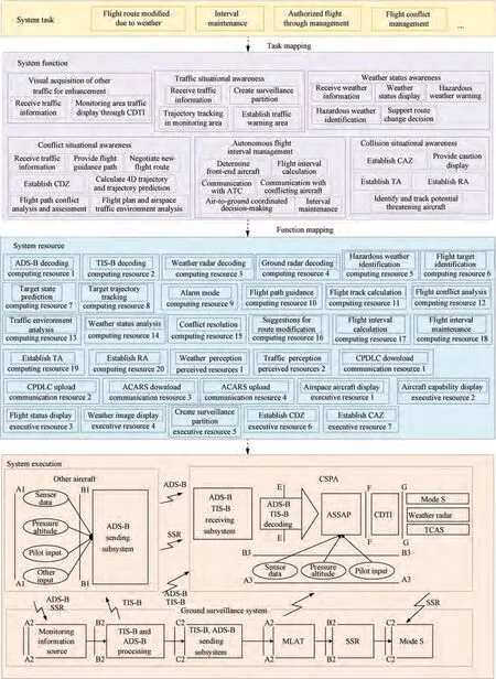
Fig. 4 SPO system architecture decomposition.
(2) System function layer
According to the surveillance function requirements proposed in RTCA DO-289 Minimum Aviation System Performance Standards for Aircraft Surveillance Applications(ASA), combined with the characteristics of free flight in SPO mode, the flight surveillance function mainly includes visual acquisition of other traffic for enhancement,traffic situational awareness, weather status awareness, conflict situational awareness, autonomous flight interval management,and collision situational awareness. Considering the subsequent function layer to resource layer mapping, the top-level functions need to be further decomposed.
(3) System resource layer
From the perspective of system design, the resources in an integrated avionics system can be understood as software or hardware entities with specific capabilities, including computing units and network communication modules, which can be called remotely. Integrated avionics system resources can be divided into four types: computing resource, communication resource, perceived resource, and execution resource.Based on the specific description of each function in RTCA DO-289,the corresponding functions can be mapped to specific resources through establishing system function operating model.
(4) System execution layer
The execution layer mainly receives the command from the airborne bus,completes system instruction,and feeds back the related system executing parameters to the core processing module of the resource layer to realize the closed-loop control of the system. As shown in Fig. 4, it depicts the system execution process and the interfaces between functional elements.
3. DFCluster algorithm
With the expansion of system integration scope and the increase of integrated functions, task organizing mode becomes complicated, in particular, the problems of multicapability organization, multi-process organization, and multi-task organization caused by task synthesis will make the classic analysis methods become incompetent to provide dependable results. Hence, we use the method of hazard pattern mining to assist traditional safety analysis.
The calling relationship between functions and resources can be abstracted into a matrix, where each row represents a resource and each column represents a function. The values in the matrix represent the extent to which a resource supports a function. Therefore, by mining the function-resource matrix of two different tasks,it can find out which resources and functions can meet the needs when these two tasks are executed at the same time, and which resources and functions need to be accessed over and over.
Therefore, this paper proposes a new bicluster algorithm:the DFCluster algorithm. It can effectively mine all the maximum differential-used and low-used function-resource biclusters from two discrete matrixes without candidate maintenance. Then, reasonable function-resource allocation can be found when two tasks are executed at the same time,and the hazard pattern can be deduced. The mining results can be used to rationally allocate resources, on the one hand,it can improve the efficiency of resources, and on the other hand, it can avoid safety problems caused by task synthesis.Since the number of functions is much smaller than that of resources, DFCluster takes function expansion method for mining,and several pruning strategies are designed to improve mining efficiency.The framework of the DFCluster is shown in Fig. 5. First, we scan the original function-resource matrixes,and generate differential weighted undirected functionfunction relational graph. Then, we take the depth-first method of function expansion to mine all the maximum differential-used and low-used function-resource biclusters.
3.1. Preliminaries and definitions
3.1.1. Function-resource matrix definition
Definition 1. The function-resource matrix is defined as a twodimensional real-valued matrix M = R × F, in which row R represents resource set and column F represents function set.Element Mrepresents the usage rate of resource i supporting function j.|R|is the number of resources in dataset M and|F|is the number of functions.To simplify the mining process,the original values in the function-resource matrix are usually discretized as 1,-1,and 0,where-1 means that the usage rate of the resource is the minimum during the implementation of some function, 0 means that the usage rate of the resource is moderate, and 1 means that the usage rate of the resource is the maximum, as shown in Table 1 and Table 2.
3.1.2. Function-resource bicluster definition
For example, when only task Tis executed, for a group of functions FF(F==>RRRR, F==> RRRRR),the two functions may be called simultaneously. For resource R,there are three situations for supporting Fand F:(A)for F, the usage rate of Ris high, while it is low for F; (B) for both Fand F, the usage rate of Ris high; (C) for both Fand F,the usage rate of Ris low.In this paper,we define that the safety degree in the first and third conditions are higher than that in the second one. The reason is that Rcan serve Fand Fsimultaneously in the first and third conditions,but in the second one, Rneeds to serve the two functions respectively. In addition, from the perspective of functional effectiveness, if Rfails, the degree of adverse impact on the second condition is higher than that on the first and third ones.Furthermore, this paper mainly studies the condition that the two tasks are executed in parallel, hence the situation of function calling resources will be doubled,but the core is the same,as defined below.

Fig. 5 Framework of DFCluster algorithm.

Table 1 Function-resource usage matrix of task T1.
Definition 2. In order to facilitate description of bicluster with differential usage rate and low usage rate, it is supposed that the use-values of resource Rafter discretization under the functions Fand Fof task Tare Vand V, and the usevalues of resource Rafter discretization under the functions Fand Fof task Tare Vand V. There are five representations for Runder Fand F: (A) if V= 1,V= -1, V= -1, V= -1, or V= -1, V= -1,V= 1, V= -1, the contribution rate of Rto Fand Fsatisfies the differential-used requirement, expressed as ‘R’;(B)if V=-1,V=1,V=-1,V=-1,or V=-1,V= -1,V= -1, V= 1,the contribution rate of Rto Fand Fsatisfies the differential-used requirement,expressed as‘*R’;(C)if V=-1,V=-1,V=-1 and V=-1,the contribution rate of Rto Fand Fsatisfies the low-used requirement,expressed as‘-R’;(D)if there are more than one‘1’among V,V,Vand V,the contribution rate of Rto Fand Funder Tand Tdoes not satisfy the differential-used nor low-used requirement, so no record is given; (E) if V= 0, V= 0, V= 0 or V= 0, the contribution rate of Rto Fand Funder Tand Tdoes not satisfy the differential-used nor low-used requirement, so no record is given.
Based on Definition 2, the DFCluster algorithm primarily mines the first three cases, as shown in Table 3.
3.2. DFCluster algorithm
The mining steps of the DFCluster algorithm can be divided into two steps: First, one scans the original function-resource usage matrixes of the two tasks, and generates the differential weighted undirected function-function relational graph. Then,one adopts the depth-first method of function expansion to mine all the maximum differential-used and low-used function-resource biclusters.
3.2.1. Differential weighted undirected function-function relational graph
Definition 3. Differential weighted undirected functionfunction relational graph is defined by the set L = {S, P,V}. Each node in the vertex set P in the graph represents afunction. If an edge exists between a pair of vertices, this means that the resource set under the above vertices must satisfy Definition 2. The set of all edges is denoted as S. The weights of each edge are the resource set satisfying Definition 2 under the two functions connected with this edge. The set of the weights is denoted as V.

Table 2 Function-resource usage matrix of task T2.

Table 3 Situations mined through DFCluster algorithm.
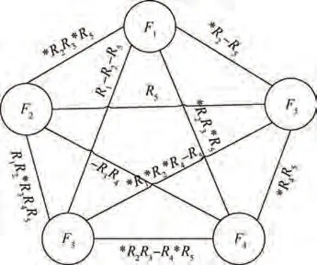
Fig. 6 Differential weighted undirected function-function relational graph based on Table 1 and Table 2.
The original function-resource datasets can be converted into a weighted undirected function-function relational graph based on Definition 3.Hence,there is no need to scan the original datasets over and over, and we can directly search for the weighted relational graph to improve algorithm efficiency.
Taking data in Table 1 and Table 2 as an example,the following weighted relational graph can be constructed,as shown in Fig.6.Based on Definition 2,the weight does not satisfy the interchangeability. For example, the weight between FFis*RR*R, while the weight between FFis R*RR. Hence,we only record the weight between FFwhen i <j, and the weight between FFcan be obtained by ‘inverting’ the weight between FF(‘R’ and ‘*R’ interchanged, ‘-R’ unchanged).
3.2.2. Mining the maximum bicluster
According to Definition 2, the extended function-resource biclusters satisfy anti-monotonicity, that is, if the functionresource bicluster obtained by FF...Fdoes not meet the constraints, then any bicluster obtained by its supersets FF-...FFalso does not meet. Hence, we can obtain a largerscale function-resource bicluster by calculating the intersection of the weights. In the traditional expansion method, if FFis extended to obtain FFF,only the weight on the edge of FFand FFneeds to be intersected to obtain the resource set under FFF. However, this traditional expansion method is not applicable in the DFCluster algorithm. Here we must intersect the weights of FF,FF,and FFto get the resource set under FFF. Only in this way can we avoid two or more‘1under FFF.Hence,when introducing a new function,it is necessary to intersect all the newly introduced function edges with the resource set of the extended function-resource bicluster. When calculating the intersection of the weights, we only need to calculate the intersection of the resources without considering the‘*’or ‘-’symbol in front of the resources, that is,the resources with different symbols can also be intersected.These symbols are only used in the following pruning design.
3.3. Pruning strategy
Traditional bicluster mining algorithms are divided into the following categories:
(1) Bicluster mining algorithm based on traditional clustering: cluster the rows and columns of the matrix separately, and then merge the clustering results, but it cannot fully find the local patterns.
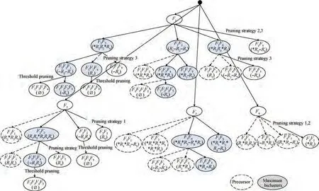
Fig. 7 Example mining process of DFCluster algorithm.
(2) Greedy iterative search algorithm:the greedy strategy of bicluster mining is more efficient, but the clustering result is easy to fall into the local optimum.
(3) Bicluster exhaust algorithm:exhaust algorithm can fully find customized bicluster, which is more suitable for resource integration safety analysis.
In fact, DFCluster algorithm belongs to bicluster exhaust algorithm whose time complexity is relatively high. Hence,algorithmic techniques, such as pruning strategy, should be added to optimize the exhaustive process, thereby ensuring the efficiency of the algorithm.The pruning strategy can avoid repeated searches for the subset of the bicluster that has been mined, which greatly simplify the mining process and shorten the running time.
Predecessor detection is applied in the DFCluster algorithm to judge the maximum bicluster without candidate maintenance, that is, if resources under the candidate function have an inclusion relationship with those under a certain prior function that has been already extended,then all the biclusters generated by the candidate function can also be generated by the prior function, hence the candidate function can be pruned to greatly improve the mining efficiency.
Lemma 1. Assuming that E is the function-resource bicluster to be extended currently, C is the candidate function set of E and P is the prior function set of E.For any resource Runder the candidate function C(C∈C),if its representation is‘R’,and there is a prior function P(P∈P)and also a resource‘R’under P, then resource Runder function Ccan be previously extended by the prior function P.
Proof. Proof by contradiction. Assuming that, for any resource Rin the candidate function C, its representation is ‘R’, if there is a prior function P, and representation of resource Runder Pis also ‘R’, then resource Runder function Ccannot be extended by the prior function P. Since Runder the candidate function Cis represented as‘R’,‘1’must exist under a certain function in E, and Ris ‘-1’ under both the candidate function Cand the prior function P. Hence,the current extended function-resource bicluster is differential-used bicluster, and considering that each resource can only have one ‘1’ under all functions in differential-used biclusters, the differential-used bicluster obtained by ECextension can be obtained by EPCextension, which contradicts the hypothesis. Therefore, the original proof (Lemma 1)holds.
Pruning strategy 1. If Cshould be pruned, it must satisfy all of the following criteria. (A) EC.Function is the subset of EP.Function; (B) EC.Resource is the subset of EP.Resource; (C) if the expression form is ‘R’ for any resource Rin candidate function C(C∈C),there is a prior function P(P∈P) under which resource ‘R’ also exists.
Lemma 2. Assuming that E is the function-resource bicluster to be extended currently, C is the candidate function set of E and P is the prior function set of E.For any resource Runder the candidate function C(C∈C),if its representation is‘*R’,there is a prior function P(P∈P)and a resource Runder P,and the representation of Ris ‘-R’, then resource Runder function Ccan be extended by the prior function P.
Proof. Proof by contradiction. Assuming that, for any resource Rin the candidate function C, its representation is ‘*R’, if there is a prior function P, and there is also a resource ‘-R’ under P, then resource Runder function Ccannot be extended by the prior function P. Since resource Rin the candidate function Cis represented as ‘*R’, then‘1’ exists under the candidate function C, and Runder all functions in P is ‘-1’. Resource Runder the prior function Pis represented as‘-R’,then Runder Pis also‘-1’.Hence,the current extended function-resource bicluster is differentialused bicluster, and considering that each resource in differential-used bicluster can only have one‘1’under all functions,the differential-used bicluster obtained by ECextension can be obtained by EPCextension, which contradicts the hypothesis. Therefore, the original proof (Lemma 2) holds.
Pruning strategy 2. If Cshould be pruned, it must satisfy all of the following criteria. (A) EC.Function is the subset of EP. Function; (B) EC.Resource is the subset of EP.Resource; (C) if the expression form is ‘*R’ for any resource Rin candidate function C(C∈C),there is a prior function P(P∈P)under which resource Rwith the expression form of ‘-R’ also exists.
Lemma 3. Assuming that E is the function-resource bicluster to be extended currently,C is the candidate function set of E and P is the prior candidate function set of E. For any resource Runder the candidate function C(C∈C),if its representation is‘-R’,there is a prior function P(P∈P)and a resource Runder P,and the representation of Ris‘-R’,then resource Runder function Ccan be extended by the prior function P.Proof. Proof by contradiction. Assuming that, for any resource Rin the candidate function C, its representation is ‘-R’, if there is a prior function P, and there is also a resource ‘-R’ under P, then resource Runder function Ccannot be extended by the prior function P. Since resource Runder Cis represented as‘-R’,then the resource Runder Cis‘-1’,and Rmay be‘-1’under all functions in E or‘1’in a certain function. Also, resource Runder the prior function Pis represented as ‘-R’, and Runder Pis ‘-1’. Hence,the differential-used bicluster or low-used bicluster EPCcan be extended by EP, and the function-resource bicluster obtained by ECextension can be obtained by EPCextension, which contradicts the hypothesis. Therefore, the original proof (Lemma 3) holds.
Pruning strategy 3. If Cshould be pruned, it must satisfy all of the following criteria. (A) EC.Function is the subset of EP.Function; (B) EC.Resource is the subset of EP.Resource; (C) if the expression form is ‘-R’ for any resource Rin candidate function C(C∈C),there is a prior function P(P∈P)under which resource Rwith the expression form of ‘-R’ also exists.
Pruning strategy 4. Assuming that E is the functionresource bicluster to be extended currently, C is the candidate function set of E and P is the prior function set of E. If, for each resource Runder the candidate function C(C∈C),there is the same prior function P(P∈P),under which each resource Rsatisfies Pruning strategy 1, 2 or 3,then the candidate function Ccan be pruned.
Output strategy: Assuming that E is the function-resource bicluster to be extended currently, C is the candidate function set of E and P is the prior candidate function set of E. If all candidate functions C(C∈C)for E satisfy Pruning strategy 4, and there is no prior function P(P∈P) such that E.Resources is a subset of EP.Resources,then E can be output.For candidate functions Cthat do not satisfy Pruning strategy 4, EC.Resources is a subset of E.Resources, and if there is no prior function P(P∈P)that makes E.Resources a subset of EP.Resources, then E.C can be output.
The DFCluster algorithm is used in Table 1 and Table 2,and the mining process is shown in Fig. 7.
The detail of the DFCluster algorithm is shown in the following Algorithm 1.
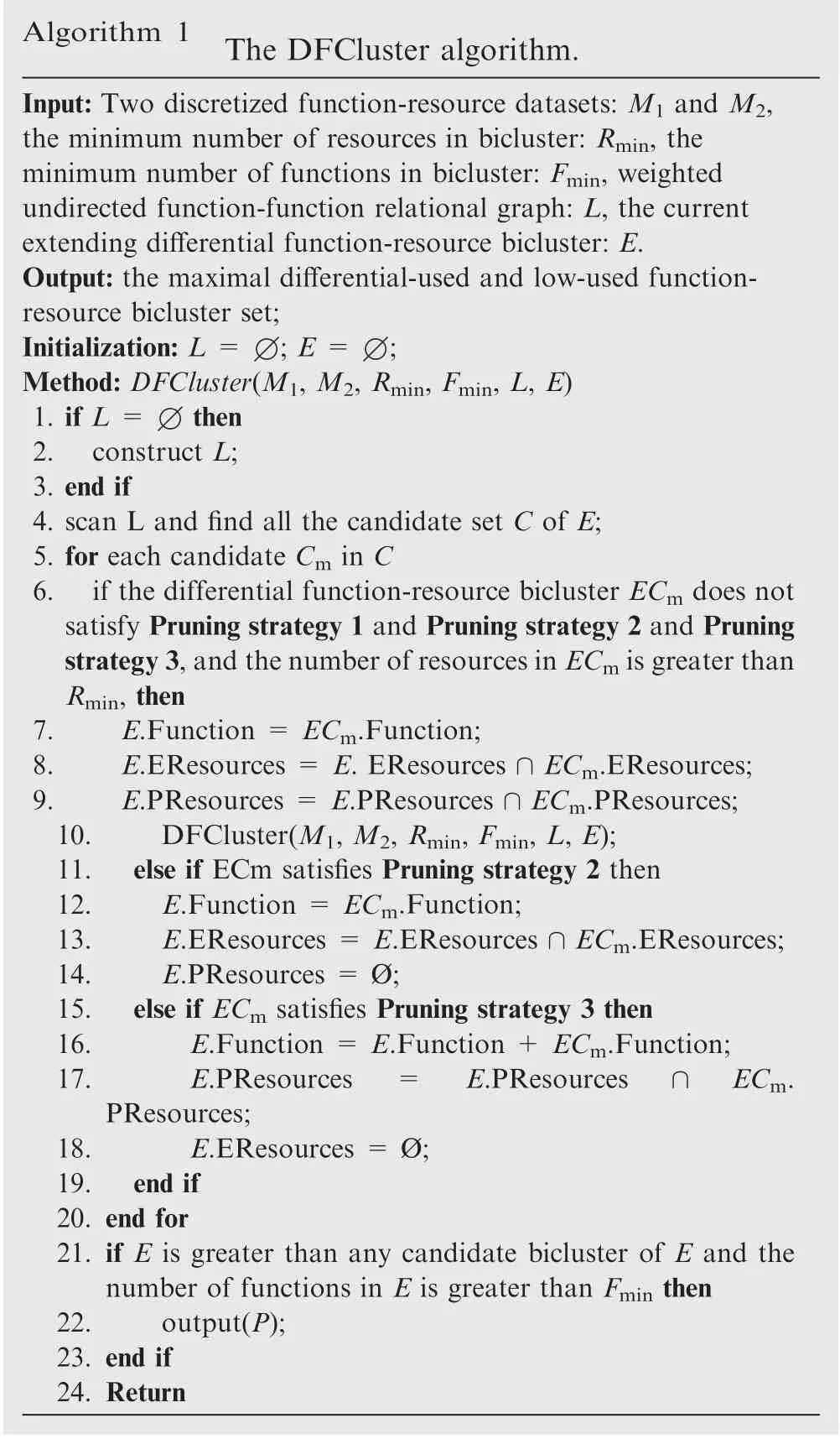
Algorithm 1 The DFCluster algorithm.Input: Two discretized function-resource datasets: M1 and M2,the minimum number of resources in bicluster: Rmin, the minimum number of functions in bicluster: Fmin, weighted undirected function-function relational graph: L, the current extending differential function-resource bicluster: E.Output: the maximal differential-used and low-used functionresource bicluster set;Initialization: L = ∅; E = ∅;Method: DFCluster(M1, M2, Rmin, Fmin, L, E)1. if L = ∅then 2. construct L;3. end if 4. scan L and find all the candidate set C of E;5. for each candidate Cm in C 6. if the differential function-resource bicluster ECm does not satisfy Pruning strategy 1 and Pruning strategy 2 and Pruning strategy 3,and the number of resources in ECm is greater than Rmin, then 7.E.Function = ECm.Function;8.E.EResources = E. EResources ∩ECm.EResources;9.E.PResources = E.PResources ∩ECm.PResources;10.DFCluster(M1, M2, Rmin, Fmin, L, E);11. else if ECm satisfies Pruning strategy 2 then 12.E.Function = ECm.Function;13.E.EResources = E.EResources ∩ECm.EResources;14.E.PResources = Ø;15. else if ECm satisfies Pruning strategy 3 then 16.E.Function = E.Function + ECm.Function;17.E.PResources=E.PResources∩ECm.PResources;18.E.EResources = Ø;19. end if 20. end for 21. if E is greater than any candidate bicluster of E and the number of functions in E is greater than Fmin then 22.output(P);23. end if 24. Return
4. Experiment and analysis
4.1. Efficiency comparison
The mining efficiency and mining results of our proposed algorithm and existing algorithms are compared experimentally.The hardware environment of the experiments is a notebook computer:Intel(R)Core(TM)CPU,4G memory,the software environment is:Microsoft Windows 10 OS,and the algorithm programming and running environment are Microsoft Visual C++ 6.0. The experimental dataset comes from the gene database AGEMAP and man-made datasets.
DFCluster algorithm will be compared with DiBiCLUS algorithm, SDC algorithm, and DECluster algorithm. Among them, DiBiCLUS first identifies the differential pairs of items in each class, due to the constraints of the algorithm, there is only one differential co-expression type for each pair of items,and then it uses clustering to merge the differential coexpression pairs that have been generated,to mine all the maximum differential biclusters. In order to ensure the quantity and quality of the biclusters,DiBiCLUS introduces a parameter dto constrain the generation of differential co-expression biclusters.The smaller the value of d,the looser the constraint on differential biclusters and the more differential coexpression biclusters will be mined. The larger the value of d, the less differential co-expression biclusters will be mined,but the better the quality of the results. SDC uses the original Apriori concept to mine all differential patterns. The original SDC algorithm can only mine differential co-expression patterns, while our implemented SDC algorithm can mine subspace differential biclusters. SDC algorithm introduces SDC support to control the number of biclusters. The smaller the SDC support, the looser the constraint on differential coexpression biclusters and the more differential biclusters will be mined. Conversely, the fewer biclusters will be mined, but the more the co-expression characteristics will be. SDC first mines all the differential co-expression biclusters, and finally only outputs the maximum biclusters through judgment.DECluster mines all the maximum differential co-expression biclusters based on the weighted undirected sample-sample relational graph through sample expansion, and designs several pruning techniques to improve the mining efficiency.
The experiments of the above four algorithms will be carried out in discretized datasets. Therefore, the values in the original AGEMAP dataset will be discretized into 1, -1, and 0 through K-means clustering proposed in the DiBiCLUS algorithm. The use of K-means for discretization has certain drawbacks, that is, the results obtained by discretization may be different each time,because the selection of the initial center point may be different.Hence,to avoid the influence caused by the selection of center point, each data will be discretized 10 times, and the result with minimum mean square error will be output.
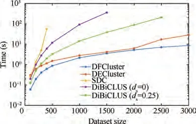
Fig. 8 Runtime of different algorithms on different sizes of AGEMAP database.
Since the above four algorithms introduce different parameters to control the generation of differential biclusters, in order to persuasively illustrate the efficiency of the DFCluster algorithm,the principle of parameter setting is to enable DiBi-CLUS,SDC,and DECluster to obtain the highest mining efficiency, and the parameter of each algorithm is set as follows.(A) DFCluster. There is no need to introduce differential coexpression support to constrain the mining, and the minimum functions and resources in function-resource biclusters are set at 2. (B) SDC. Since the SDC algorithm uses the apriori concept to extend biclusters, the larger SDC support can result in less time consumed and best results. Hence, we set the SDC support to 1. Due to the inefficiency of the SDC algorithm,the minimum thresholds for the number of items and samples are set to 3 and 7, respectively. (C) DiBiCLUS. In order to fully compare the efficiency of DiBiCLUS, the parameter dis set to 0 and 0.25 respectively, and the minimum thresholds for the number of items and samples are both set to 2. (D)DECluster. DECluster produces biclusters without any differential co-expression threshold relaxation. The minimum samples and items in the DC bicluster are set at 3.
(1) Resource scalability
The number of functions is fixed to 12, and the number of resources is set to 100, 200, 300, ..., 3000. By comparing the running time of the above four algorithms, as shown in Fig. 8, it can be seen that the overall running time shows the law of‘DFCluster <DECluster <DiBiCLUS(d=0.25)<-DiBiCLUS(d= 0) < SDC’, and when the number of resources is larger, the advantage of the DFCluster algorithm is more obvious. Since the apriori concept is used for mining and no pruning strategy is adopted,the SDC algorithm cannot produce results within one hour when mining the dataset of 500 resources.DiBiCLUS algorithm saves the results produced in the memory,which greatly affects the efficiency and scalability of the algorithm. When the number of resources reaches 1500, DiBiCLUS (d= 0) algorithm causes a memory crash;when the number of resources reaches 2500, the DiBiCLUS(d= 0.25) algorithm also causes a memory crash. When the number of resources reaches 3000, DFCluster can still complete mining within 10 s, and DFCluster (8.696 s) is more than 3 times faster than DECluster (28.624 s).
(2) Data density
The number of functions is fixed at 10, the number of resources is fixed at 200, and datasets with different ratios of 1/-1/0 are man-made to compare the running time and results of the above four algorithms. It can be seen from Fig. 9 that when the proportion of 0 is fixed at 0.5, regardless of the proportion of 1 and -1, the overall running time still shows‘DFCluster < DECluster < DiBiCLUS(d= 0.25) <-DiBiCLUS(d= 0) <SDC’ rule. When the proportion of-1 increases,the running time of the DFCluster also increases,because when the ratio of-1 becomes larger,based on Definition 2, the number of mined differential-used and low-used function-resource biclusters will increase accordingly. It can be seen from Fig. 9 that when the ratio of 1 and -1 becomes larger, that is, the denser the data are, the mining time of DFCluster also becomes longer. However, compared with other algorithms, DFCluster still maintains a greater advantage.
(3) Pruning strategy analysis
DFCluster will be compared with DFCluster without pruning,DFCluster with pruning1,DFCluster with pruning 2,and DFCluster with pruning 3 in man-made datasets of different sizes to analyze the effect of pruning strategy. It can be seen from Fig. 10 that the overall running time still shows the law of‘DFCluster <DFCluster with pruning 3 <DFCluster with pruning 2 <DFCluster with pruning 1 <DFCluster without pruning’.DFCluster without pruning shows the lowest mining efficiency due to repeated mining work, while the efficiency of DFCluster with pruning 3 is the second-highest because Pruning strategy 3 greatly simplifies the process of mining low-used function-resource biclusters. When the dataset increases to 25 functions and 500 resources, the mining efficiency of DFCluster(13.026 s)is about twice that of DFCluster without pruning(21.736 s), and as the dataset increases, the advantage of DFCluster becomes more obvious,which shows that the pruning strategy we designed has greatly improved the mining efficiency of the algorithm.
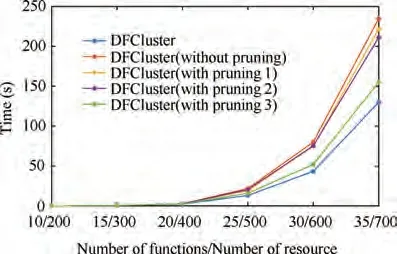
Fig. 10 Pruning strategy analysis of DFCluster algorithm.
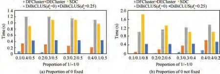
Fig. 9 Comparison 1 and comparison 2 of running time of different data densities.

Fig. 11 Experimental framework for model-based analysis.
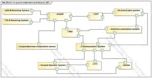
Fig. 12 System organizing structure model.
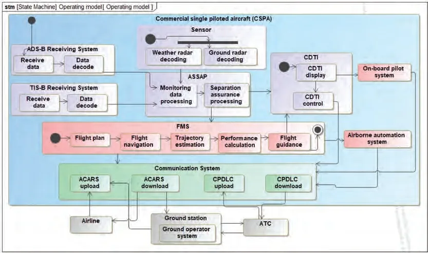
Fig. 13 System operating model.
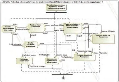
Fig. 14 Function decomposition model of T1.
In summary, efficiency comparison study shows that DFCluster has the best overall performance among the algorithms tested. The scalability study shows that DFCluster scales well even with large databases. The data density study shows that regardless of the density of the database, DFCluster still maintains a greater advantage in mining efficiency.The pruning strategy analysis shows the effectiveness of the pruning strategy in improving mining efficiency, especially in large databases.
4.2. Model-based analysis
We use a real designed experiment to show how to use our proposed algorithm for SPO system safety analysis. First, we design a typical flight scenario in SPO mode and model the system organizing structure and system operating architecture through Magic System of System.Then,the functional layer decomposition and resource mapping of typical tasks are modeled to extract the function-resource matrixes of different tasks. Finally, the DFCluster algorithm is executed to mine the maximum differential-used and low-used biclusters to support safety analysis of task synthesis.The experimental framework is shown in Fig. 11.
The typical flight scenario designed in SPO mode is as follows: As shown in Fig. 1 above, in the airspace authorized by ATC,CSPA detects weather threats ahead,and then builds an autonomous route to avoid hazardous weather. It obtains airspace traffic information through ADS-B and TIS-B,analyzes flight status and intentions of other aircraft in the airspace through FMS, and establishes collision detection that violates minimum isolation.Then,a flight conflict is found,FMS automatically generates an alert and provides the pilot with several flight path modification methods to resolve potential conflicts.The onboard pilot cooperates with the conflicting aircraft through voice communication to complete the avoidance process, and the conflict resolution process is completed by them autonomously.
Based on the surveillance requirements of the land-based cruise in SPO mode,the task synthesis of T(construct autonomous route due to severe weather)and T(autonomous flight interval management) in the above flight scenario will be analyzed.First,the system organizing structure model and system operating model,which involve the interaction among ADS-B,TIS-B, ASSAP, FMS, CDTI, onboard pilot system, airborne automation system, communication system, ground operator system,ATC,airlines,and so on,are built through Magic System of System. The specific models are shown in Fig. 12 and Fig. 13 respectively.
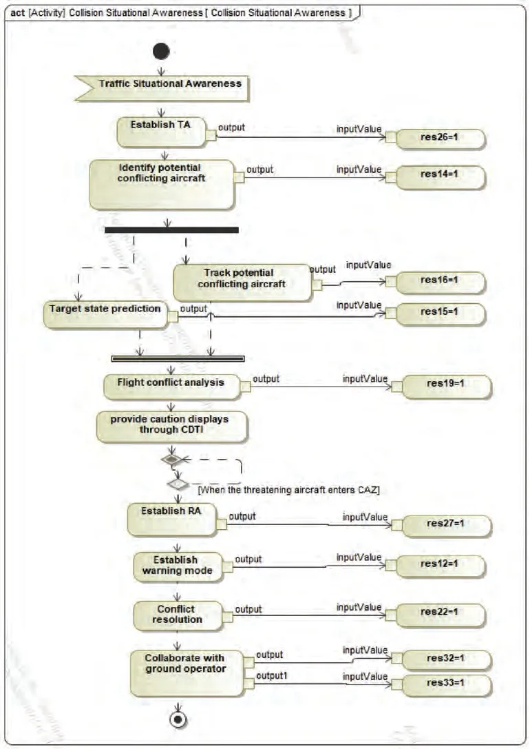
Fig. 15 Resource calling model within function of collision situational awareness.
Then, each task is decomposed into the function layer, for example, Fig. 14 shows the function decomposition model of T.Next,the resource calling model is constructed within each function.Taking the function Collision Situational Awareness shown in Fig. 15 as an example, based on the function Traffic Situational Awareness, it establishes traffic Threat Advisory(TA),detects traffic information in traffic alert areas,identifies and tracks potential threatening aircraft,and provides caution displays through CDTI. When the threatening aircraft enters the air Collision Avoidance Zone (CAZ), the collision avoidance Resolution Advisory(RA)is established,and the air collision avoidance warning is generated. FMS provides conflict resolution for the onboard pilot and ground operator to make air-to-ground coordinated decision-making adopt collision avoidance maneuvers.
Finally,we can extract the function-resource matrixes of Tand T, and data are obtained through human evaluation, as shown in Table 4 and Table 5 respectively. Functions Fto Frespectively represent receiving traffic/weather information,traffic situational awareness, weather status awareness, visual acquisition of other traffic for enhancement, conflict situa-tional awareness, collision situational awareness, autonomous flight interval management, and flight route modification.Resources are divided into computing resources, executive resources, perceived resources and communication resources,as shown in Table 6.
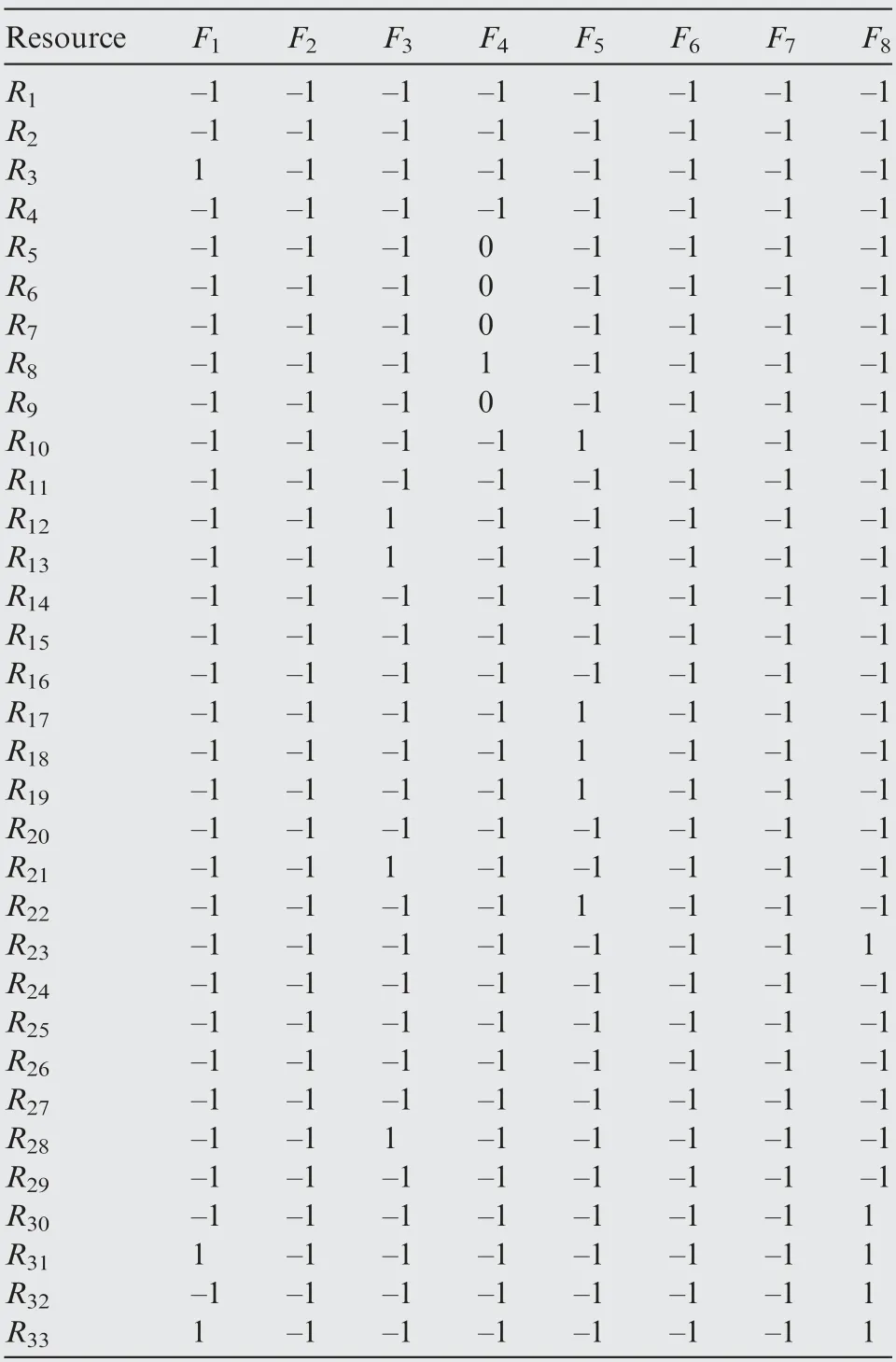
Table 4 Function-resource matrix of task T1.
Then DFCluster algorithm will be executed in the above matrixes. Its running time is 0.017 s and 89 function-resource biclusters are mined, some of which are shown in Fig. 16.
It can be found that the communication resources R,R,R, Rcaused the most conflicts during the execution of the above two flight tasks. This is because, in SPO mode, ground operators need to receive relevant airspace information through the ACARS download link to complete flight monitoring and coordinated decision-making. In addition, the ground operator needs to feed back some decision-making suggestions and control instructions to the pilot on board through the ACARS upload link. Due to the limited bandwidth of ACARS and the lack of a response mechanism,problems such as communication delay and incomplete information transmission may occur.
Based on the above analysis, we consider adding a new communication link - command and control (C2) link, which is dedicated to the communication between onboard pilot and ground operator,while ACARS still serves the communicationbetween CSPA and airline. The newly designed SPO airground collaborative architecture is shown in Fig. 17.
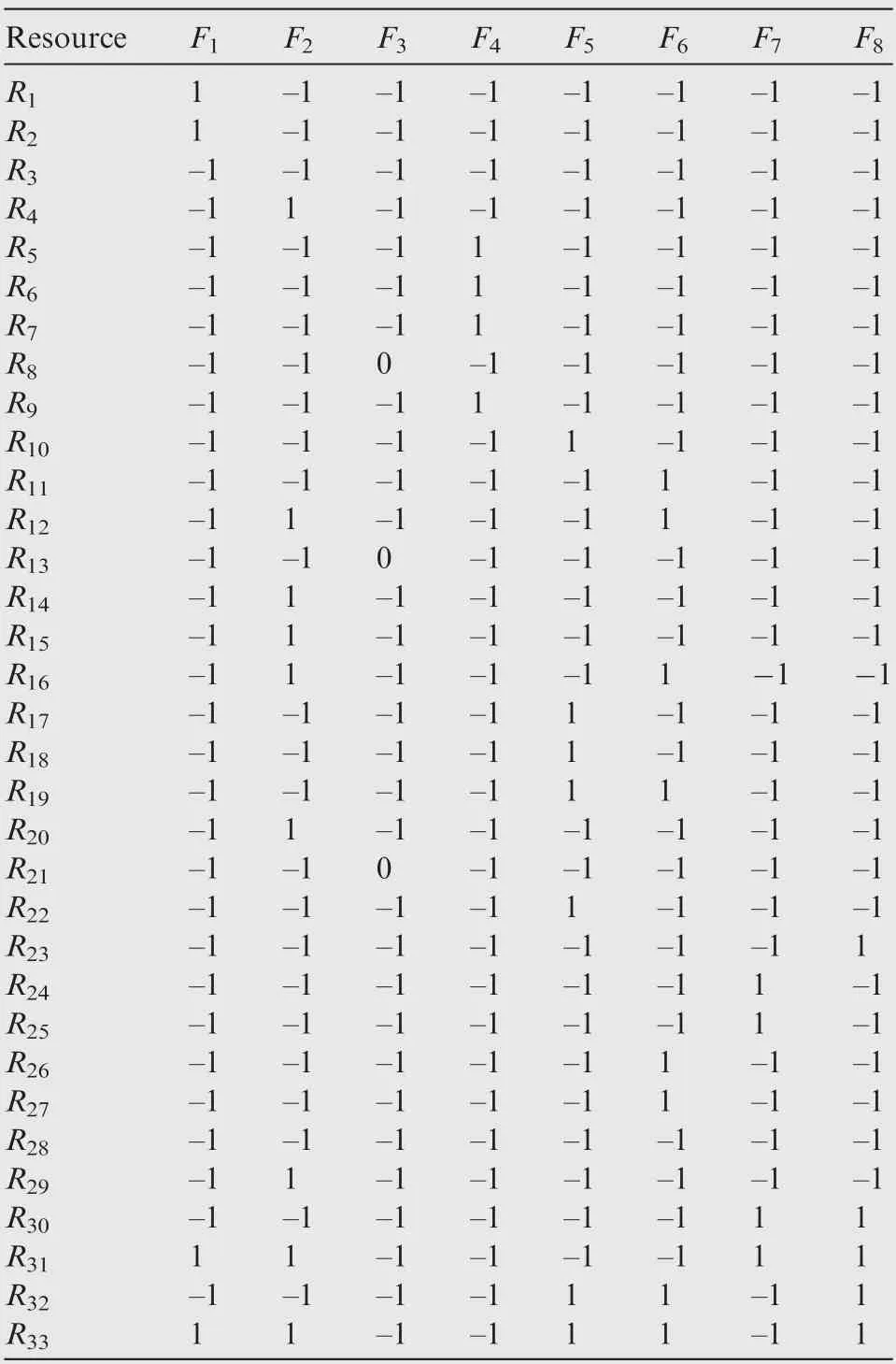
Table 5 Function-resource matrix of task T2.
After adding resources R(C2 download link)and R(C2 upload link), the new function-resource matrixes of Tand Twill be extracted.Then DFCluster algorithm is applied to mine maximum differential-used and low-used function-resource biclusters, and it is found that the conflicts caused by communication resources are greatly reduced under the new airground collaborative architecture. During the execution of the air-ground cooperative task, we manually insert conflicts between calling functions and resources,and through the analysis of mining results produced by the DFCluster algorithm,the potential hazard patterns can be identified effectively.Therefore, our proposed DFCluster algorithm can help find the fault cause when executing several tasks at the same time,which will help to improve task synthesis safety analysis.
4.3. Application prospect discussion
Generally,the safety analysis of the civil aircraft is carried out in the aircraft design stage.With the rapid development of civil aircraft digitization,there are a large number of system models in the design stage. Our proposed algorithm can be applied tomine and analyze the model operating data, and then some potential hazard pattern or more reasonable functionresource allocation could be found to guide safety analysis and system architecture design. Besides, in terms of aircraft upgrade,such as future improvement to C919,a large amount of data have been accumulated during the operation of C919.Through the mining and analysis of these data, more reasonable resource allocation could be obtained, which is meaningful for improving the flight performance.
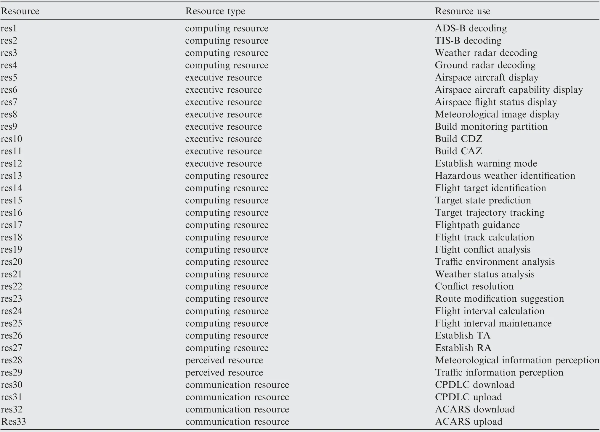
Table 6 Details of resource.
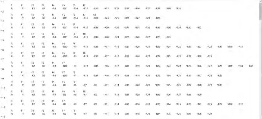
Fig. 16 Part of mining results.
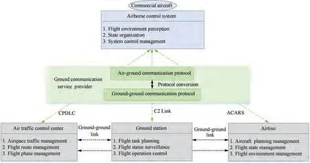
Fig. 17 Newly designed SPO air-ground collaborative architecture.
5. Conclusions
To make SPO mode reach the same level as the current dualpilot operating mode and reduce the workload of the on-board pilot, it needs to further strengthen system integration including task synthesis, function fusion, and resource integration,and the high level of system integration will improve efficiency but also introduce safety issues.Due to the iteration of the system design,it is difficult to ensure the consistency of the failure modes with the system architecture. Therefore, to solve the inconsistency between the system architecture design model and the safety analysis model, Model-Based Safety Analysis(MBSA) is applied in this paper. We designed a typical flight scenario in SPO mode, modelled the system organizing structure and system operating architecture, then completed the layer-by-layer decomposition from task layer, function layer,resource layer, and execution layer, and extracted the function-resource matrixes of different tasks. To cope with the increasing number and complexity of system failure modes in the context of task synthesis, DFCluster algorithm is applied to assist task synthesis safety analysis of different tasks execution.In order to mine efficiently,the differential weighted undirected relational graph is used to store raw data instead of the double-checking method,and several pruning strategies are designed for mining maximal biclusters without candidate maintenance. Based on the mining results, the SPO airground collaborative system architecture gets modified, which ultimately improves the safety of the SPO system.
The authors declare that they have no known competing financial interests or personal relationships that could have appeared to influence the work reported in this paper.
This study is supported by National Program on Key Basic Research Project (2014CB744903), National Natural Science Foundation of China(61673270),Natural Science Foundation of Shanghai (20ZR1427800), New Young Teachers Launch Program of Shanghai Jiaotong University (20X100040036),Shanghai Pujiang Program (16PJD028), Shanghai Industrial Strengthening Project (GYQJ-2017-5-08), Shanghai Science andTechnologyCommitteeResearchProject(17DZ1204304), and Shanghai Engineering Research Center of Civil Aircraft Flight Testing.
