Design and experimental research of a sub-Newton N2O monopropellant thruster with inner-heater
Kiyng LI, Jie FANG, Wei SUN, Bing SUN, Guoio CAI
a School of Astronautics, Beihang University, Beijing 100083, China
b Key Laboratory of Spacecraft Design Optimization and Dynamic Simulation Technologies of Ministry of Education,Beihang University, Beijing 100083, China
c China Academy of Space Technology, Beijing 100094, China
KEYWORDS Green propellant;Monopropellant thruster;Nitrous oxide;Regenerative heat compensation;Self-pressurization
Abstract Nitrous oxide (N2O) is a green propellant with excellent application prospects. A sub-Newton N2O monopropellant thruster with inner-heater and a N2O self-pressurization stable supply system with regenerative heat compensation are designed in this paper. The experimental research of the thruster is described, including measurements of preheating power, activation temperature,vacuum thrust,specific impulse,life-span and pulsed operation performance.By inserting the heater into the catalyst-bed, preheating efficiency of the heater is significantly improved compared to the thruster with outer-heater. Thus, the preheating power demand of the thruster is successfully reduced to around 10 W. The mean vacuum thrust of 322 mN is attained and the corresponding specific impulse reaches 162 s at the mass flow rate of 0.2 g/s. Successful activation temperature of 523 K is achieved, and the activation performance of the thruster is affected by the loading factor.A long term hot-firing test longer than 12000 s is attained.The pulsed operation performance of the inner-preheating thruster is also studied by measuring chamber pressure.Impulses with different magnitudes are produced by adjusting the opening duration of the control valve. A minimum impulse of 81 mN·s is attained. Finally, the performance of the thruster is evaluated by comparison with other thrusters of the same type. The results indicate that the proposed thruster with inner-heater is superior in terms of preheating power, activation temperature and specific impulse performance.
1. Introduction
As a new generation of satellites, microsatellites have great application potential in the military community due to their characteristics of light weight, cost effectiveness, short development cycle and flexible launch method.The key to the development of microsatellite technology lies in the miniaturization of various instruments and equipment.A propulsion system is the primary mobility system of a satellite which helps with its maneuvering operations. Therefore, in order to meet the mobility needs of microsatellites, there is great interest in developing monopropellant propulsion systems.
Cold Gas Propulsion systems are the earliest types of monopropellant propulsion systems.The main components of these systems include a pressurized tank and a nozzle. The thrust is generated by the controlled ejection of compressed liquid or gas in the tank. Due to the absence of combustion process, a Cold Gas Propulsion system can be designed with minimum complexity and very small size. However, their performances are limited (typically, specific impulses range from 10 s to 80 s), which restricts their application in highly demanding missions. Moreover, changes in tank pressure can cause the instability of the thrust generated, which is not conducive to maneuver control of the spacecraft.
Warm Gas Propulsion systems are an upgraded version of Cold Gas Propulsion systems. In these systems, an external source is used to heat the working fluid, which improves the internal energy of the working medium and leads to an increase in specific impulse of the system.Compared to the Cold Gas Propulsion systems, Warm Gas Propulsion systems have better performance in terms of specific impulse.However,they consume a large amount of energy, which puts a burden on the energy system of the microsatellite. This suggests the need for a system in which a propellant exothermically decomposes to produce a mixture of high pressure hot gases in the chamber, supported by a suitable catalyst, and then these products are accelerated by the nozzle to generate the thrust.Such kinds of systems require decomposable propellants. The commonly used working fluids for this purpose include hydrazine (NH), hydrogen peroxide (HO) and their derivatives.NHhas played a successful role in monopropellant systems,because of its active chemical properties, high vapor pressure and durability. HOis a monopropellant which was developed three decades earlier than hydrazine technology.Although the specific impulse performance of HOis 40%lower than that of NH,its environmentally friendly products(water and oxygen) and low cost make it a highly promising propellant even today.However, these conventional propellants have their own limitations, and alternative propellants provide better performance on some special missions that cannot be performed with NHor HO. Therefore, it is necessary to develop advanced propellants to meet the possible mission requirements of spacecrafts in the near future.
Nitrous oxide(NO)is considered a potential monopropellant for micro-thrusters applied in micro-spacecrafts as a result of its special properties, such as non-toxicity, selfpressurization,and self-sustaining reaction.It has drawn great interest from research institutions due to its low cost and low handling hazard.
Numerous related studies have been reported at universities, such as the University of Surrey, Tsinghua University,Stanford University and Toronto University. The University of Surrey made great efforts to verify the feasibility of using NO as a monopropellant by analyzing the properties of NO and comparing it with conventional and alternative propellants.The researchers tested more than fifty different catalysts for NO catalytic decomposition, and finally achieved repeatable, self-sustaining decomposition of NO with certain catalysts. An activation temperature as low as 523 K and a decomposition temperature more than 1773 K were recorded.They found that NO decomposition inside the decomposer is a flow-controlled process and the start-up transient time for NO decomposition is shorter with higher energy input.They also summarized the characteristics of the NO decomposition process in a catalyst-bed.However, most of the studies at Surrey were obtained for non-choked flow at ambient pressure.Thereafter, the research at Tsinghua University aimed at the hot firing of choked NO flow. Based on Surrey’s work,researchers at Tsinghua successfully reduced the size of NO decomposer as well as the start-up transient time from 15 min to 52 s.In addition, they developed a model for the simulation of a NO monopropellant thruster operation.Researchers at Stanford University designed and tested a NO mono-propellant gas generator for propulsion and power applications.Different from the studies at Surrey and Tsinghua Universities, Stanford’s gas generator was operated at higher NO mass flow rates ranging from 0.9 g/s to 2.3 g/s.High efficiency of the characteristic velocity under steady state was demonstrated with loading factors up to 15 kg/(m·s) in the gas generator. They also studied the effects of lean CH/NO mixtures on the reaction initiation.In order to meet the requirements of a reference microsatellite, Space Flight Laboratory (SFL) at University of Toronto developed a NO-based monopropellant with 100 mN thruster, based on SFL’s nitrous oxide resistojet. Then, the prototype thruster was manufactured and tested in the vacuum chamber. It was found that the monopropellant system achieved an average specific impulse of 131 s (25% increase over the original one), while consuming minimal power.Prior to the SFL’s study, Brazilian Instituto Nacional de Pesquisas Espaciais(INPE)implemented an experimental investigation of a monopropellant 2 N thermal-catalytic prototype thruster using gaseous NO.The results showed that the catalytic decomposition efficiency of NO was relatively high (~88%), that is, the experimental specific impulse could reach 88% of the theoretical impulse.
Beihang University(BUAA)has been dedicated to developing a sub-Newton NO thruster since 2005.The concept of the NO monopropellant thruster,which uses an electric heating wire to preheat the catalyst-bed, was proposed and fabricated in the initial research phase. The numerical simulation of the thermodynamic properties of decomposition productswas carried out and the influencing factors of the thruster performance were discussed in this phase, which provided a wealth of knowledge for subsequent research. Considering the high saturation characteristics of NO, a selfpressurization feeding systemwas designed to supply propellant to the thruster and a detailed theoretical analysis of the self-pressurization was carried out. Subsequently, a complete ground experimental system of the NO monopropellant propulsion systemwas built, and experiments were conducted on NO self-pressurization and thruster performance measurement. Experimental and simulated results from previous research indicated that the self-pressurization feeding system was feasible and the performance of the thruster was superior. However, there are two shortcomings that need to be improved: the tank pressure decreases during the NO self-pressurization process, which may cause an unstable supply of NO propellant,and the energy efficiency of the preheating power is very low due to the heat loss during the heat transfer process between the outer chamber-wall and the catalyst-bed. Therefore, this study aims to further improve the performance of the thruster by addressing the shortcomings of the current system.
In present work, a thruster with an inner-heater and NO self-pressurizing stable supply system was designed and introduced in Section 2 and Section 3,respectively.Then,an experimental investigation of the thruster with inner-heater was carried out, and the main performance parameters of this system were measured, including preheating power, activation temperature, vacuum thrust, specific impulse, life-span of the thruster, as well as pulsed operation performance (Section 4).In addition, the performance of the thruster was evaluated by comparing with other NO monopropellant thrusters.Finally, the main conclusions of this study are listed in Section 5.
2. Design of thruster with inner-heater
The thrusters used in early studies(comprehensively described in Ref.) are preheated with an electric heating wire wrapped around the reaction chamber. The heat flow is transferred through the chamber-wall into the catalyst-bed. Therefore,the reaction chamber needs to be preheated to a temperature higher than activation temperature. As the total thermal capacitance of the reaction chamber is much higher than that of the catalyst, most of the preheating power is used for heating the reaction chamber, which leads to a very low efficiency of energy utilization. In addition, the demand for the initial temperature of an NO monopropellant thruster usually surpasses 523 K, which is higher than that of a conventional hydrazine monopropellant thruster.Due to the low preheating efficiency and high requirement for the initial temperature, a thruster with outer-heater usually requires a preheating power higher than 30 W in previous experiments. As is known, the power generated by a power system onboard a small spacecraft is limited, so the power supplied to the propulsion system is strictly limited. Hence, guaranteeing the preheating capability is a major problem for the practical application of the NO monopropellant thruster.
In order to improve the preheating efficiency, a thruster with an inner-heater is designed and fabricated. As shown in Fig. 1 (a), a cylindrical inner heater with dimensions of∅4 mm × 20 mm is inserted into the catalyst-bed to directly preheat the catalyst. The inner heater is set in the upstream part of the catalyst-bed to avoid the influence of high temperature, which usually appears at the downstream region of the catalyst-bed, so as to extend the service life of the heater.The thruster is fabricated by stainless steel (1Cr18Ni9Ti), as shown in Fig. 1 (b), with inner-diameter of ∅11 mm. The length of the catalyst-bed is 25 mm. As the heater is inserted from the axial direction, the propellant inlet is set on the side-wall. A conical nozzle with ∅1.5 mm throat is integrated in the reaction chamber. The divergence angle is 30°, and the expansion ratio is 178.
3. N2O self-pressurization stable supply system scheme for a sub-Newton thruster
Due to the high saturated vapor pressure of NO liquefied gas,a self-pressurization tank can be used in NO supply system,which dramatically simplifies the system. However, the pressure in the tank decreases during NO supply process. When the pressure drop exceeds the adjustable range of the pressure regulator, the falling pressure may affect the stable NO supply, which can further influence the stability of the thrust. In order to avoid the instability of the thrust caused by the pressure drop in the tank, a stable NO supply system is designed in this section.
3.1. Simulation study on N2O tank self-pressurization process
In previous research,a three-region lumped model for the tank was proposed based on Zilliac’s model,and the simulation results were in good agreement with the experimental measurements. This model includes three regions: a bulk gas region, a bulk liquid region and a liquid surface layer. The model assumptions are as follows:
(1) The convection heat-transfer rate between bulk liquid and the liquid surface layer is much higher than the natural convection heat-transfer rate.
(2) The vaporization rate is proportional to the convection heat-transfer rate between bulk liquid and the liquid surface layer.
(3) The boundary between NO and the tank’s inner-wall is adiabatic.
(4) The pressure throughout the tank is uniform.
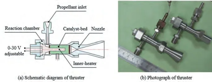
Fig. 1 Thruster with inner-heater.
(5) The temperature and composition in the bulk gas region and the bulk liquid region are uniform, and the temperature of liquid surface layer is the saturation temperature under the tank pressure.The key to achieve a stable supply of NO is to reduce the tank pressure drop. According to the above uniform pressure assumption and the actual gas equation of state, the pressures of the bulk gas and the bulk liquid are uniform, and the formula is:

where Pand Pare the pressures of the bulk liquid and the bulk gas,respectively;R is the universal gas constant;T represents the temperature of NO gas; a and b are both Van der Waals constants, which respectively reflect the gravitational force between gas molecules and the molecular volume; Vis the molar volume of NO, and its value is only related to T under the same pressure.
As seen from Eq. (1), temperature is the main factor that affects the tank pressure. The heat compensation of the NO tank can maintain the temperature in the tank,which indicates that it is feasible to achieve the tank pressure stabilization by means of heat compensation.In order to explore the influence of heat compensation on the tank pressure, the three-region lumped model (comprehensively described in Ref.) is used to simulate the NO self-pressurization process. Several simulation cases, including the power and location of the external heat source,are listed in Table 1.The initial conditions of these simulation cases, including tank volume (10 L), initial filling factor (0.6 kg/L), mass flow rate (0.71 g/s) and initial tank pressure (5.46 MPa), are consistent with the experiment.According to the law of energy conservation,the conservation equation of energy for an open system is:

where ˙Qis the net rate of heat entering into the control volume; E is the total internal energy of the control volume; ˙mand ˙mrepresent the mass flow rate of NO outflowing from and entering the control volume, respectively; hand hare the specific enthalpy of the outflowing NO and the entering NO, respectively; ˙W is the net rate of work output from the control volume.
This equation is applicable to both the bulk liquid and the bulk gas. When considering heat compensation, for the bulk gas region,the heat source term ˙Qin Eq.(2)can be expressed as:

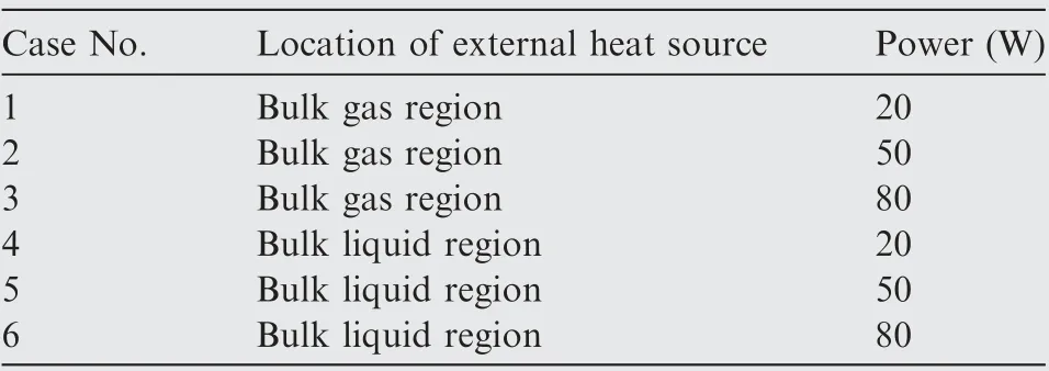
Table 1 Simulation cases of N2O self-pressurization process with external heat source.

Other equations of the model,including the main governing equations, state equations and supplementary equations, are fully listed in Ref.. Based on the simulation cases listed in Table 1, the tank pressure drop curves are simulated during the NO self-pressurization, and the simulation results are shown in Fig. 2. The results indicate that heat compensation can slow down the pressure drop in the tank. When the external heat source is installed in the bulk liquid region, it consumes less power.
3.2. N2O self-pressurization stable supply system scheme
Based on the simulation results, a NO self-pressurization stable supply system scheme with regenerative heat compensation is proposed,as shown in Fig. 3, and the components of the system are listed in Table 2.The regenerative heat compensation module of the system consists of the NO tank, thrust chamber components, nozzle hot end heat exchange components, tank cold end heat exchange components, and pipeline cold end heat exchange components. NO gas overflows from the outlet of the tank and flows to two branches.One branch is connected to the thruster,which is called the Propellant Supply Branch (PSB). The other branch is connected to the regenerative heat compensation module, which is called the Regenerative Heat Compensation Branch(RHCB).The NO gas in PSB is used to generate thrust in the thruster, while the NO gas in RHCB is used as a heat transfer medium. The heat generated by the decomposition of NO is collected by the nozzle hot end heat exchange components, and then transferred to the tank cold end heat exchange components and pipeline cold end heat exchange component for heat exchange.
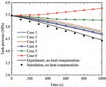
Fig. 2 Simulation results of tank pressure.
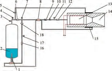
Fig. 3 Sketch of a N2O self-pressurization stable supply system with heat compensation (the components of the system are listed in Table 2).
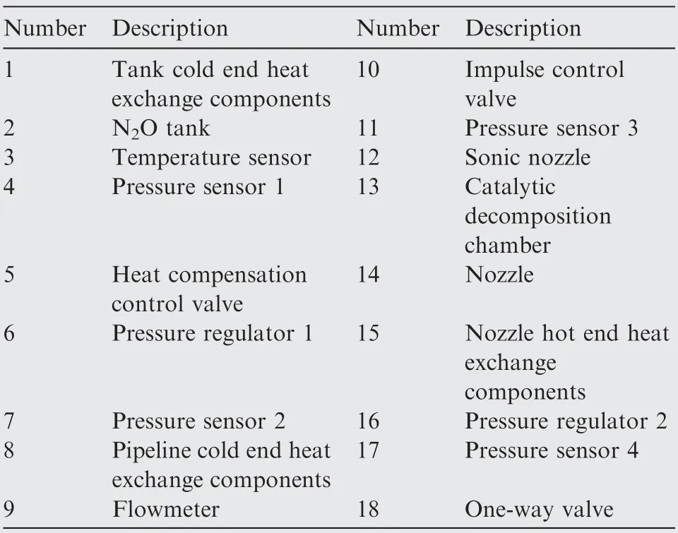
Table 2 Description of components of supply system.
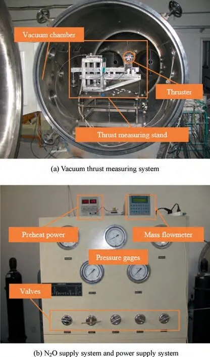
Fig. 4 Ground vacuum experimental system.
The system can achieve a stable supply of NO due to the following two aspects. First, the regenerative heat compensation module transfers heat to the tank, so that the pressure in the tank can be maintained within the range that can be adjusted by the pressure regulator. Second, the regenerative heat compensation module also transfers heat to the pipeline cold end heat exchange components and evaporates the small amount of liquid in the NO gas in the PSB into a gas,thereby improving the control accuracy of the NO gas mass flow rate.Moreover,since the system uses NO as the heat transfer medium and the nozzle generation as the heat source, it can not only save valuable energy of the spacecraft, but can also provide thermal protection for the thruster in practical applications.
4. Measurements for thruster with inner-heater
In order to study the vacuum performance of the thruster with inner-heater, a vacuum experimental system (described in Ref.) is employed, as shown in Fig. 4 (a). In this system,the thruster is installed on the vacuum thrust measuring stand in the vacuum chamber, and the NO supply system and the power supply system for preheating are placed outside the vacuum chamber, as shown in Fig. 4 (b).
4.1. Preheating power measurement
Preheating power measurement is first conducted in a vacuum chamber to evaluate the preheating performance of the thruster with an inner-heater.The outside of the thruster is wrapped with glass fiber fabric and aluminum foil for heat insulation,as shown in Fig. 5, and preheating powers of 10 W and 13.5 W are used to heat the catalyst-bed.As seen from the temperature curve in Fig.6,the catalyst-bed can be heated to 530 K within 5800 s using preheating power of 10 W. It is verified by later experiments that the thruster can start at this temperature,which demonstrates that the power of 10 W can meet the preheating demand of the thruster. When the power is increased to 13.5 W, the temperature of the catalyst-bed is further increased and the temperature rise rate is accelerated.
Compared to the power demand of a thruster with outerheater, which is higher than 30 W, the thruster with an inner-heater shows significantly improved preheating performance. Although the duration for preheating is long, it can be reduced by simplifying the overall structure and employing better heat insulation measures.
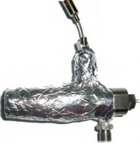
Fig. 5 Thruster with heat insulation.
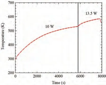
Fig. 6 Catalyst-bed temperature curve in a preheating test with an inner-heater.
4.2. Activation temperature measurement
The activation temperature is an important indicator reflecting the performance of the thruster. When this temperature is lower,the energy consumption of the preheating system is also less. Previous research has demonstrated that a 0.1 N thruster can be activated at an initial catalyst-bed temperature of 523 K,and a 1 N thruster can be activated at 623 K.In this section, the activation performance of the thruster with an inner-heater is studied.Iridium impregnated modified alumina is employed as the catalyst,which is compactly loaded into the reaction chamber of the thruster to form the catalyst bed.Several layers of glass fiber fabric are wrapped on the thruster for heat insulation. When the heater preheats the catalytic bed to the preset temperature, NO gas is supplied to the thruster.The results of the start tests conducted with different mass flow rates and catalyst-bed temperatures are listed in Table 3.
The experimental results verify that 523 K is a reliable activation temperature for the thruster. The initial temperature is varied between 603 K and 513 K in the first group of tests(1#),and the lowest successful activation temperature (523 K) isrecorded (1#-4), which shows that the thruster with innerheater can be started at 523 K.It is also found that the activation temperature of the thruster is related to the loading factor.This is directly reflected in the second group of tests (2#), in which the loading factors are reduced from 2.10 kg/(m·s) to 0.53 kg/(m·s), and the initial temperature is 523 K. The first three tests (2#-1, 2#-2, 2#-3) are successfully activated while the last test (2#-4) is failed, which indicates that a very low loading factor may be detrimental to the start performance of the thruster. This is because the heat generated by the decomposition of NO at a small flow rate may not be sufficient to maintain the catalyst-bed temperature.
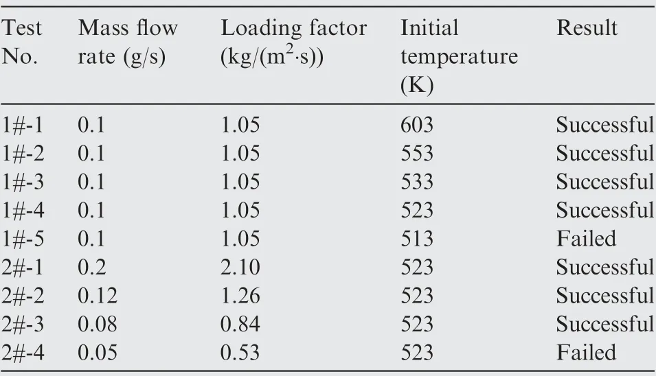
Table 3 Results of start tests at different initial conditions.
4.3. Vacuum thrust and specific impulse measurement
The vacuum thrust measurement is conducted, and the mass flow rate is adjusted between 0.2-0.3 g/s. As shown in Fig. 7,the thruster is successfully started at an initial temperature of 523 K with a NO mass flow rate of around 0.2 g/s in Section Ⅰ.The catalyst-bed temperature increases rapidly at the beginning,and reaches the highest value of 1023 K.During this process, the steady-state vacuum thrust remains around 322 mN,and the mean specific impulse reaches 162 s. In Section Ⅱ, the mass flow rate is increased to 0.32 g/s, and the thrust is stable around 489 mN. However, the catalyst-bed temperature reduces from 993 K to 913 K during this period. After that,the mass flow rate is adjusted to around 0.22 g/s again in Section III. The steady-state thrust is 343 mN, and the catalystbed temperature rises to 1027 K during this process. Subsequently, the mass flow rate is adjusted briefly to 0.248 g/s in Section Ⅳ, and the catalyst-bed temperature drops slightly.In the final section, the mass flow rate is maintained around 0.21 g/s. Accordingly, the thrust and the catalyst-bed temperature stabilize at 324 mN and 1013 K, respectively. Table 4 summarizes the performance parameters during steady-state operation of Sections Ⅰthrough V in Fig. 7.
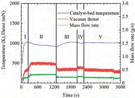
Fig. 7 Vacuum thrust measurements for thruster with an innerheater.
The experimental results show that when NO mass flow rate is close to 0.2 g/s (Sections Ⅰ, III, V), the heat of NO decomposition in the catalyst-bed can achieve the selfsustaining reaction, and the thrust and specific impulse of the thruster improve. On the contrary, when NO mass flow rate is close to 0.3 g/s (Sections Ⅱ, Ⅳ), the temperature of the catalyst-bed of the thruster decreases, and the thrust and specific impulse performance also decrease. Therefore, the thruster designed in this paper can achieve better performance at the NO flow rate of 0.2 g/s.
4.4. Life-span measurement
A long term hot-firing test is carried out to evaluate the lifespan of the thruster.The NO mass flow rate used in the thruster is 0.2 g/s,and 2.2 g catalyst is filled in the catalyst bed.The test process and results are listed in Table 5.
At the beginning of the test,the catalyst-bed is preheated to 523 K, and NO gas is introduced to evaluate the cold start performance of the thruster. Then, the temperature of the catalyst-bed is allowed to drop to 523 K, and the long term hot-firing test is carried out. After the test, four consecutive start tests are carried out, and only the first test is found to be successful.
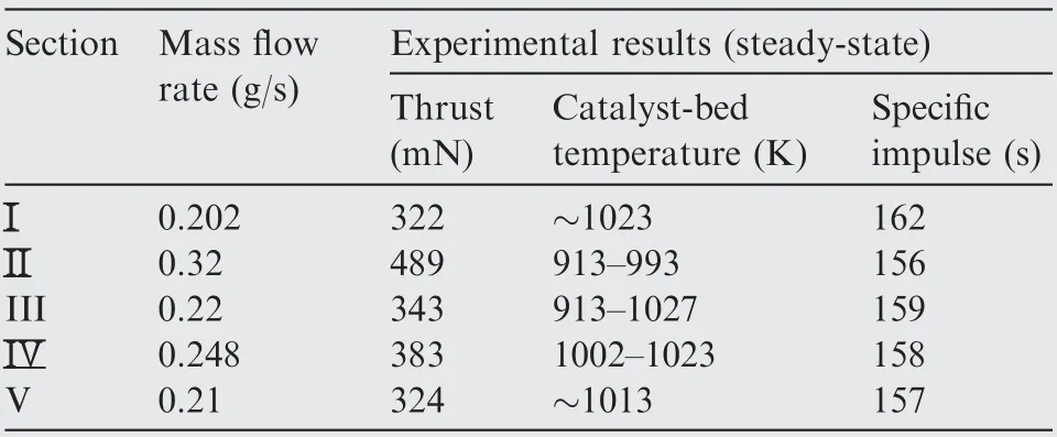
Table 4 Test performance parameters during steady-state operation regions.
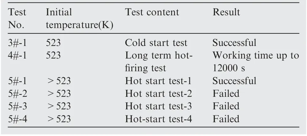
Table 5 Test process and results of life-span measurement.
As shown in Fig. 8, in the cold start test, the catalyst-bed temperature increases after the introduction of NO gas,which proves that the thruster is successfully started.Then,the thruster with inner-heater is re-started, and operates continuously for about 12000 s (4#-1). However, the catalyst-bed temperature, mass flow rate and thrust are slowly reduced during the long term hot-firing test, which indicates deterioration in the performance of catalyst. It is also found that the start performance of the thruster becomes worse after hot-firing. This is reflected in the fifth group of tests(5#),where the thruster cannot be re-started after the first start test (5#-1).
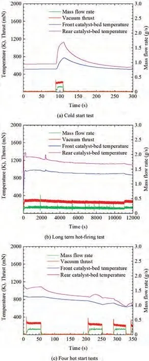
Fig. 8 Process of life-span measurement.
The thruster structural components and catalysts after the hot-firing test are shown in Fig. 9. From these pictures, it can be seen that the thruster components are basically intact,but some catalyst particles appear off-white, which indicates inactivation of the catalyst. Therefore, the life-span of the thruster is mainly determined by the life of the catalyst.
4.5. Pulsed operation performance test
The pulsed operation performance of the thruster with the∅11 mm×25 mm reaction chamber is evaluated by conducting impulse measuring experiments. The thruster is continuously operated for 240 s to ensure a high initial temperature of catalyst-bed before impulse measurements. When the catalyst-bed temperature is stable, impulses with different magnitudes are produced by adjusting the opening duration of the control valve. As shown in Fig. 10, valve-on durations of 1 s, 500 ms, 300 ms, 200 ms and 100 ms are tested in the experiments. A transient pressure peak appears each time the control valve is opened, which is caused by a transient rise in mass flow rate at the valve-open moments. The temperature of the catalyst-bed gradually decreases, because the heat loss rate is higher than the heat generation rate under pulsed working condition.
The pressure curves of impulses with different widths are compared in Fig. 11. The chamber pressure reaches a peak value at 30 ms after sending out the valve-open signal. However,it needs around 200 ms to return to a stable value.Therefore, the chamber pressure of the 100 ms impulse keeps on decreasing during the whole working process. It can also be found that there is a peak in the chamber pressure curve.After the valve-open signal is given, it takes 10 ms for the chamber pressure to reach 90% of the steady-state pressure value, and 27 ms for the initial peak.
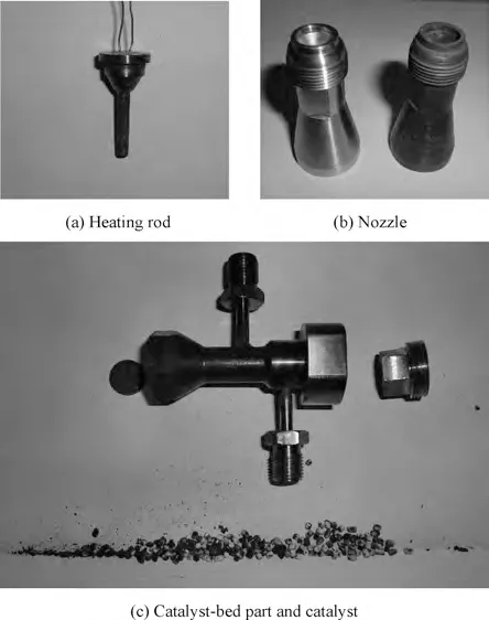
Fig. 9 Pictures of thruster components after hot-firing test.
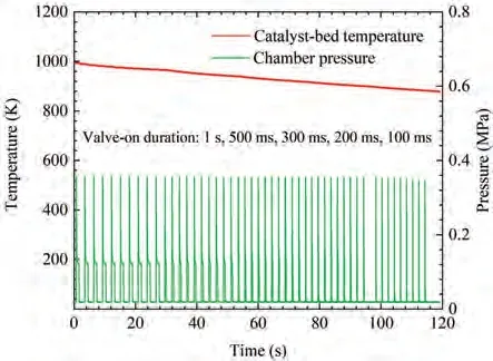
Fig.10 Impulse measurement with different valve-on durations.
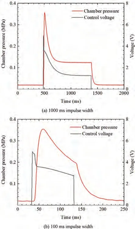
Fig. 11 Pressure curves of single impulses with durations of 1000 ms and 100 ms.
Due to the facility limit, the current vacuum experimental system could not be used for transient thrust measurement.Thus, the impulse magnitude is evaluated by comparing the pressures measured under stable and pulsed operation conditions according to the following equation:
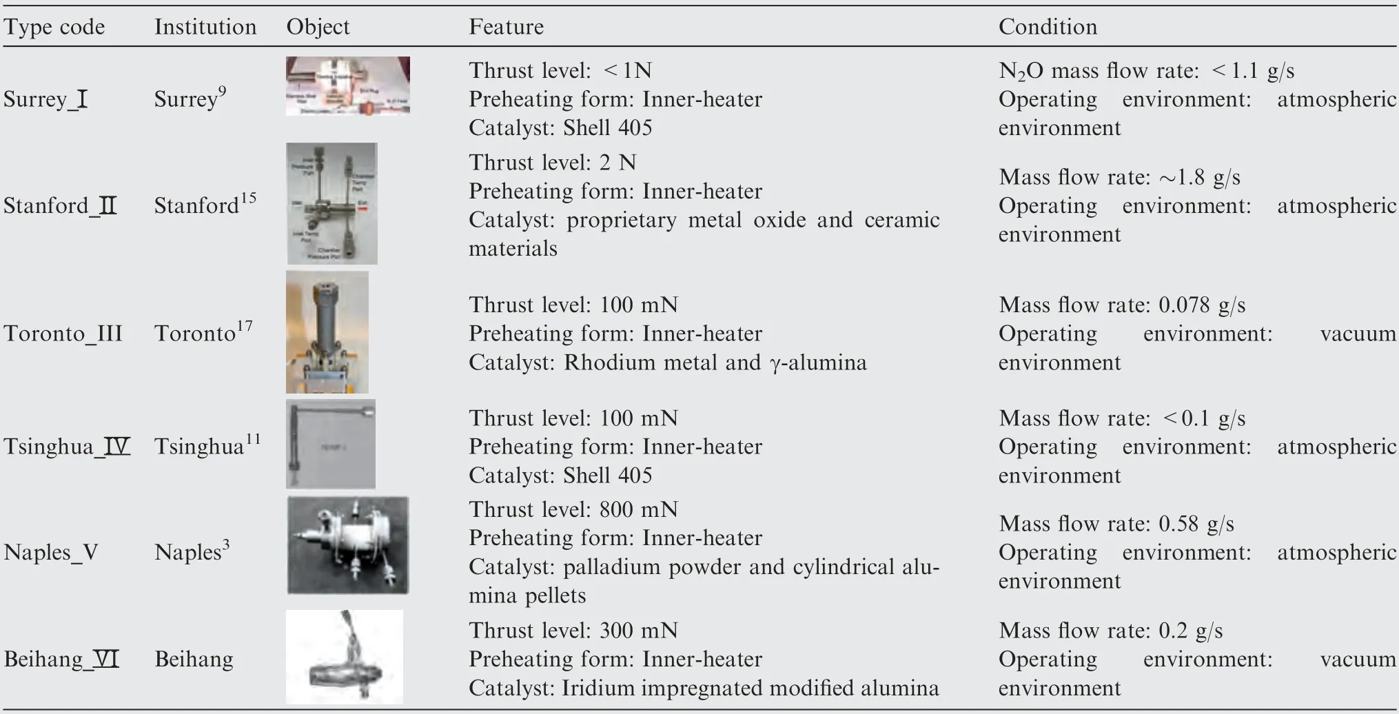
Table 6 Description of several N2O monopropellant thrusters.

Table 7 Performance indicators of different thrusters for comparison.

where Iis the impulse magnitude; Fand Fare the stable thrust and the transient thrust, respectively; Pand Pare the chamber pressures measured under stable and pulsed operation conditions, respectively. Results of integration indicate that the impulse magnitude with 1000 ms width is 355 mN·s,and that with 100 ms width is 81 mN·s.
4.6. Performance evaluation
Compared with previous studies,the thruster with inner-heater is optimized in terms of preheating power. In order to further evaluate the performance of the thruster,its performance indicators, including preheating power, activation temperature,specific impulse and life-span, are compared with other thrusters of the same type. The research institutions and main features of these thrusters, and the experiment conditions are listed in Table 6. The corresponding performance indicators are listed in Table 7.
The comparison results in Table 7 show that the proposed thruster with inner-heater has superior performance among the same type of thrusters,especially in terms of preheating power,activation temperature and specific impulse performance. In addition, the thruster has the characteristic of rapid response under pulsed conditions, which would be helpful for the continuous altitude and orbit control adjustment of the microsatellite.
5. Conclusions
A sub-Newton NO monopropellant thruster with innerheater was designed for the propose of improving the preheating efficiency. In order to maintain the thrust stability of the thruster, a simulation study on the self-pressurization with heat compensation was carried out.The results show that heat compensation for the NO tank can effectively suppress the tank pressure drop, and it can consume less energy when the heat power is in the bulk liquid region. Based on the results,a NO self-pressurized stable supply system scheme with regenerative heat compensation was proposed. Then, the performance parameters of the thruster with inner-heater were measured in a vacuum experimental system. The experimental results can be summarized as follows:
(1) The catalyst-bed temperature was successfully heated to 530 K using preheating power of 10 W, which is 67%lower compared to the thruster with outer-heater.
(2) The activation temperatures were measured over the mass flow rate range of 0.05 g/s and 0.2 g/s. The results indicate that the thruster can be successfully activated at a temperature of 523 K, but a very low loading factor was not conducive to the activation of the thruster.
(3) The thrust and specific impulse of the thruster were measured in vacuum.The thruster can achieve better performance at the mass flow rate of 0.2 g/s, where a mean thrust of 322 mN was obtained and the corresponding specific impulse reached 162 s.
(4) The life-span of the thruster exceeded 12000 s at the mass flow rate of 0.2 g/s in the hot-firing test, which was mainly reflected in the life of the catalyst.
(5) Impulses with different magnitudes were produced by adjusting the opening duration of the control valve.The impulse magnitude was evaluated by comparing the pressures measured under stable and pulsed operation conditions. A minimum impulse of 81 mN·s was attained, and the start response time of the thruster was as low as 10 ms.
The performance of the thruster with inner-heater was further evaluated by comparison with other thrusters of the same type.The results show that the proposed thruster in this paper exhibited superior preheating power, activation temperature and specific impulse performance.
The authors declare that they have no known competing financial interests or personal relationships that could have appeared to influence the work reported in this paper.
