
On a plastic instability criterion for ultra-large radial-axial ring rolling process with four guide rolls
2022-04-27 08:21:04XuechaoLILianggangGUOFengqiWANG
Chinese Journal of Aeronautics 2022年6期
Xuechao LI, Lianggang GUO,*, Fengqi WANG
a Research & Development Institute of Northwestern Polytechnical University in Shenzhen, Shenzhen 518057, China
b State Key Laboratory of Solidification Processing, School of Materials Science and Engineering, Northwestern Polytechnical University, Xi’an 710072, China
KEYWORDS Four guide rolls;Guide force;Plastic instability criterion;Radial-axial ring rolling;Ultra-large ring
Abstract A dynamic mechanical model is proposed to describe the complexing actions of all the rolls on the ring during the ultra-large radial-axial ring rolling (RARR) process with four guide rolls.Based on the model,the calculation models for bending moment and normal stress at any section of the ring are deduced by force method.If the maximum section bending normal stress exceeds the yield stress of the ring materials, the ring will be distorted thus leading to the instability of the RARR process. According to this, a plastic instability criterion for the ultra-large RARR process with four guide rolls is developed, based on which a mathematical model to calculate the critical guide force for avoiding plastic instability of ring is obtained. The influence rule of the position of guide roll on the dangerous ring section of plastic instability is revealed, from which it is found the dangerous ring section mainly appears at the radial and axial deformation regions and the contact positions of the guide rolls and ring.The optimized layout of guide roll around the ring in favor of stability is determined to be about α1 = 61° and α2 = 119°. The plastic instability criterion is proven to be reliable from the aspects of the critical guide force, the section bending moment and normal stress and the dangerous ring section of plastic instability. Intelligent simulation case studies for the RARR process of ultra-large aluminum alloy ring indicate that the stable forming of the process can be effectively realized by regulating the guide force based on the plastic instability criterion. This work could provide a valuable guidance for the control of guide rolls and the optimization of the ultra-large RARR process with four guide rolls.
1. Introduction
The ultra-large rings, as the core component of high-end equipment such as the heavy launch vehicle and nuclear reactor,are widely employed in the fields of energy and aerospace.Produced by traditional casting and welding processes,the ring products cannot meet the performance demand for standing the hostile working environment due to severe microstructure defects.The radial-axial ring rolling (RARR) could make metal produce sufficient plastic deformation by continuous rolling to obtain uniform microstructure and excellent performance.Compared to traditional processes, it has significant advantages of high quality, high efficiency and considerable savings in energy and material cost.Therefore, the RARR process has become an irreplaceable advanced technology for producing ultra-large seamless rings.
Realizing steady rolling is the premise of successfully completing the whole rolling process and acquiring qualified ring.It is well known that the guide rolls play a crucial role in the steady rolling of the RARR process. Too big guide force will make the ring produce plastic bending deformation, leading to instability of the process. Too small guide force is not enough to support the ring in a stable state,leading to the wagging of ring. In real production, large amounts of distorted waste products are produced due to the instability caused by unreasonable control of guide rolls, as shown in Fig. 1.So,reasonably regulating the guide force and position of guide roll is the key to realizing stable forming of the ring.
For ultra-large ring, it is more difficult to remain stable forming due to the supersize of ring and the continuous weakness of ring stiffness with thickness reduction. To improve the stability of ultra-large RARR process, a new kind of RARR process with four guide rolls has been developed in the world as shown in Fig.2.Compared to conventional RARR process,two guide rolls are added on the side of the axial rolls to increase constraints on ring. But how to determine the guide force and its reasonable position becomes a key issue urgently to be solved for the stable forming of ultra-large RARR process with four guide rolls.
For establishing a successful and stable rolling process,some forming conditions have been proposed. Hua and Zhiestablished the biting and penetration conditions for radial ring rolling process,based on which Qian,et al.researched the gripping and plastic penetration conditions for groove ballsection ring rolling process. The above conditions provide an important basis for successfully establishing a radial rolling process.Zhou,et al.and Berti,et al.proposed the forming conditions in radial and axial passes to make ring rotate smoothly.These conditions not only could ensure the successful establishment of rolling process but also fully consider the deformation compatibility between radial and axial passes.Considering a constant ring growth velocity as the objective,Guo,et al.and Lee,et al.proposed the steady and feasible forming conditions for the RARR process, respectively. They established the mathematical correlation model of the key process variables and determined their reasonable ranges. This provides a theoretical guide for establishing a successful and stable radial-axial rolling process.
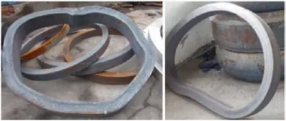
Fig. 1 Waste rings with distorted shape in actual manufacturing.9
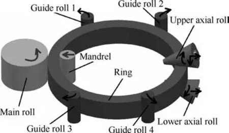
Fig. 2 Forming principle diagram of the RARR process with four guide rolls.
For ring rolling with two guide rolls, many efforts on the control of guide rolls have been done to improve stability.Hua,et al.researched the following movement of guide roller in cold ring rolling process.However,this method is not applicable to the rings with large dimension or complex shape.Based on the hydraulic adjustment mechanism, Li, et al.established a control method for guide rolls, which is more coincident with the practice and could realize the flexible control of guide rolls. Xu, et al.deduced the ring bending moment and established a plastic instability criterion for radial ring rolling process. Zhu, et al.realized the accurate control for the positions of guide rolls by establishing the relation between the positions of guide rolls and ring diameter. Hua,et al.proposed a ring stiffness condition based on a simplified mechanical model of the RARR process with two guide rolls,which actually emphasizes the allowable maximum outer radius of ring,but not the effect of guide force.To address this,Hua,et al.established a novel ring stiffness condition by force method and obtained the allowable maximum guide force for avoiding plastic instability of ring during the RARR process with two guide rolls. However, it seems that there is no study on ultra-large RARR process with four guide rolls. It is very necessary to establish a plastic instability criterion for ultralarge RARR process with four guide rolls to provide a guidance for the control of guide rolls.
The FE analysis technology has become a powerful means to study various complicated plastic forming processes.Many studies on FE simulation of ring rolling process have been reported. Han, et al.established a 3D elastic-plastic finite element model for cylindrical ring rolling process and investigated the plastic deformation behaviors of rolled rings of 20CrMnTi alloy by FE simulations.The effects of roll sizes on the forming quality of ring were extensively studied by 3DFE numerical simulations.Li, et al.investigated the influence of material properties of blank on cold ring rolling process through FE simulations. Besides, the blank design and optimization for ring rolling process were also performed by FE method.Nowadays, more and more works adopt FE method to study the microstructureand performanceduring ring rolling process. However, all the rolls’motions are predefined by experiences in the above works,thus difficult to realize coordinated control of the rolls. So, Guo,et al.proposed an intelligent simulation idea for ring rolling process with two guide rolls driven by control objective,by which the self-adaptive rolling process was realized and the rolls’ motions satisfying the control objective were obtained without predefinition. For the RARR process with four guide rolls,the coordinated control of all guide rolls is more difficult,for which the intelligent FE simulation method is more needed to be employed.
This work studies the plastic instability criterion for the ultra-large RARR process with four guide rolls by intelligent FE simulation and theoretical analysis.The purpose is to provide a basis for determining the guide force and position of guide roll to realize stable forming of ultra-large ring. Firstly,a dynamic mechanical model for the ultra-large RARR process with four guide rolls is built. Secondly, the mathematical models of section bending moment and normal stress of ring are deduced. And thus a plastic instability criterion for the ultra-large RARR process with four guide rolls is established.Thirdly, the influence rule of the position of guide roll on the dangerous ring section is revealed and the optimized layout of guide roll is obtained.The mathematical model to calculate the critical guide force for avoiding plastic instability of ring is deduced. Fourthly, the criterion is verified from the critical guide force, the section bending moment and normal stress and the dangerous ring section of plastic instability by FE simulations and a comparison with ring stiffness model of two guide rolls in literature. Finally, intelligent simulation case studies for radial-axial rolling with four guide rolls of ultralarge aluminum alloy ring are performed to expound the application of the developed plastic instability criterion.
2. Dynamic mechanical model of the RARR process with four guide rolls
2.1. Establishment of the dynamic mechanical model
After the RARR process is established successfully, the ring blank is deformed continuously in the radial and axial gaps.Therefore, the radial and axial deformation regions of ring can be regarded as two fixed ends at a certain instantaneous moment of the RARR process.
Based on the above assumption, a dynamic mechanical model for the RARR process with four guide rolls is proposed as shown in Fig. 3(a), which describes the complexing actions of all the rolls on the ring at a certain instantaneous moment of ring rolling process.In the figure,b and h are the instantaneous thickness and height of ring, respectively. A and B are the radial and axial deformation regions, which are regarded as two fixed ends. C, C, D and Dare the contact positions between the guide rolls and the ring. F, F, Fand Fare the forces applied by four guide rolls, which are called the guide forces. They are concentrated forces and point to the ring center O.
From Fig.3(a),the stress will produce in the ring under the actions of four guide rolls. If the guide force is too big, the bending normal stress on ring section may exceed the yield stress of the ring materials, leading to the plastic instability of the ring. If the guide force is too small, the ring cannot be effectively stabilized by guide roll. Therefore, reasonably controlling the guide force and position of guide roll plays a crucial role in the stable forming of ring.
Assuming that the guide forces on the two sides of deformation regions are equal,namely F=Fand F=F.The cross section throughout the ring is a unified rectangle.So,the model can be regarded as a symmetrical structure and a semicircular beam model is employed, as shown in Fig. 3(b). Ris the instantaneous outer radius of ring. P is an any section on the beam.φ is the central angle of A^P,which is called the position angle of ring section, 0 < φ < π. αand αare the position angles of guide rolls, namely the layout of guide roll around the ring, 0 < α≤π/2 and π/2 < α< π. It is a statically indeterminate structure and can be calculated by the force method.
2.2.Connotation of plastic instability criterion of RARR process with four guide rolls
From Fig. 3, when the section bending normal stress exceeds the yield stress of the ring materials, the ring produces plastic bending deformation, leading to plastic instability. To avoid plastic instability of ring, the following relation should be satisfied
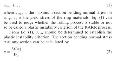
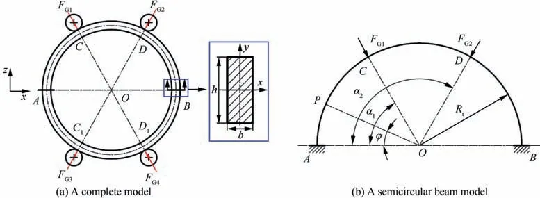
Fig. 3 Dynamic mechanical model for RARR process with four guide rolls.
where M(φ)is the section bending moment at any section,Wis section modulus in bending.For a rectangular section ring in Fig. 3(a), Wcan be calculated by
From Eq. (3), Wis known at a certain moment of rolling process, so σ mainly depends on M(φ). Based on Fig. 3(b), M(φ) can be solved by the force method below.
3.Mathematical model of bending moment at any section of ring
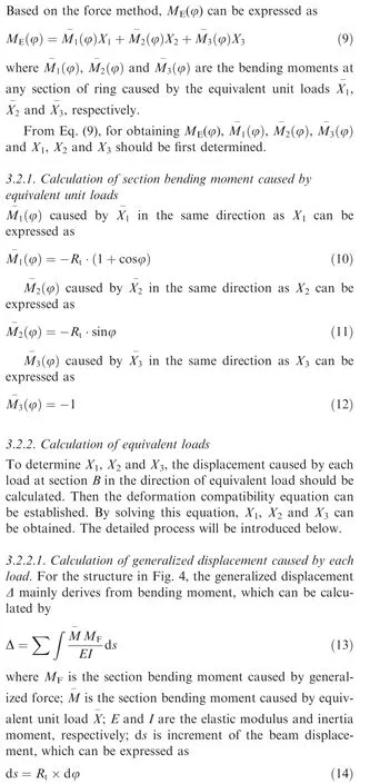
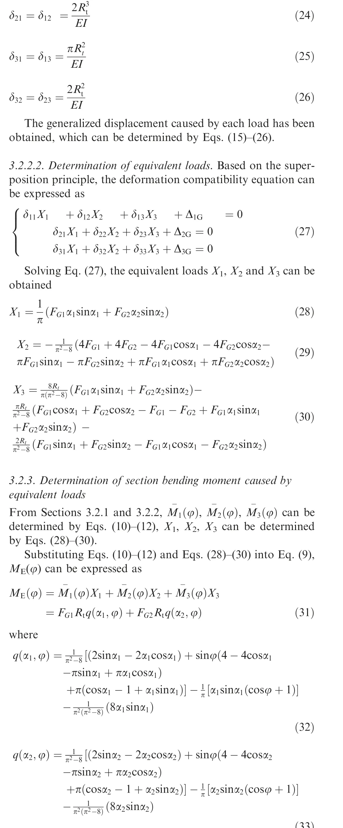
To solve the section bending moment M(φ) at any section by the force method, the fixed joint at section B is removed and an equivalent load is added, as shown in Fig. 4. Xand Xare the equivalent forces in the horizontal and vertical directions, respectively, and Xis the equivalent moment.
From Fig. 4, M(φ) is caused by both the guide forces and the equivalent loads. Based on the superposition principle,it can be expressed as

where M(φ) and M(φ) are the section bending moment at any section caused by the guide forces (Fand F) and the equivalent loads (X, Xand X), respectively.
3.1. Calculation of section bending moment caused by guide forces

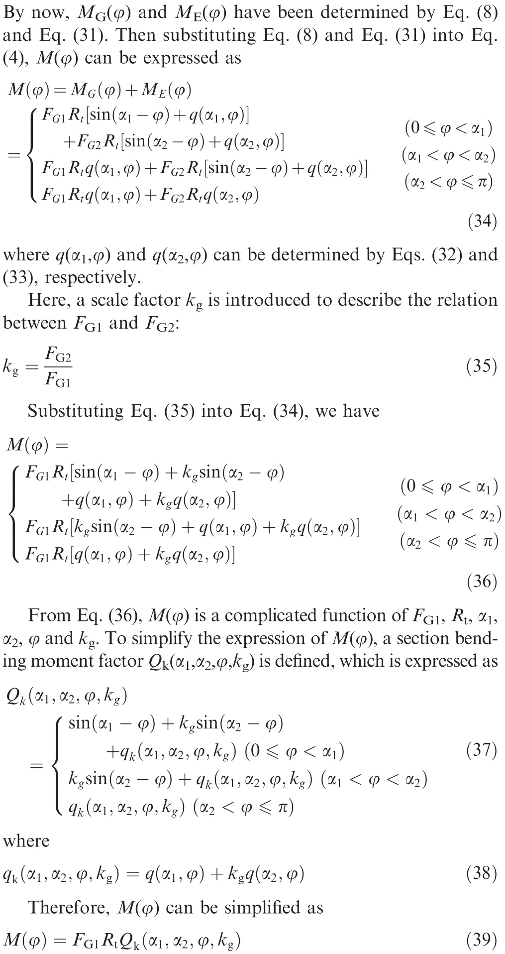
Substituting Eqs. (6) and (7) into Eq. (5), M(φ) can be expressed as
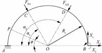
Fig.4 Equivalent mechanical model of semicircular beam based on force method.

3.2.Calculation of section bending moment caused by equivalent loads
where dφ is the increment of the position angle of ring section.
According to Eq.(13),the generalized displacement caused by guide forces and equivalent unit loads can be calculated.
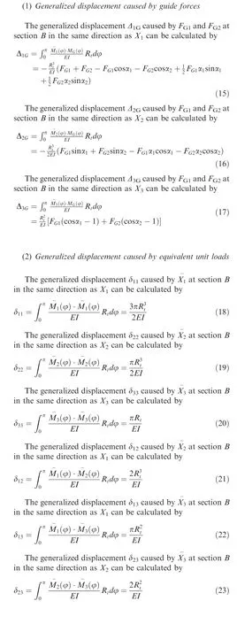
According to the reciprocal theory of displacement, we have
3.3.Determination of mathematical model of bending moment at any section
4. Plastic instability criterion for the RARR process with four guide rolls
4.1. Establishment of plastic instability criterion
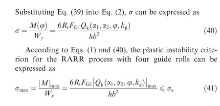
where |M|is the maximum absolute value of M(φ); |Q(α,α,φ,k)|is the maximum absolute value of Q(α,α,φ,k).
4.2. Discussion on plastic instability criterion
From Eq. (41), at a certain moment of rolling process, the forming stability depends mainly on |Q(α,α,φ,k)|and F.In Eq.(37),Q(α,α,φ,k)is related to the layout of guide rolls (α, α), the position angle φ of ring section and the scale factor kof guide forces.So,the influences of the above factors on plastic instability of ring are discussed as follows.
4.2.1. Influence of positions of guide rolls on dangerous ring section
The section having the greatest bending normal stress is most likely to produce plastic instability,which is called the dangerous ring section. To reveal the influence of positions of guide rolls on the dangerous ring section, the influence of positions of guide rolls on Q(α,α,φ,k) is discussed. The scale factor k= 1 is first considered.
Fig.5 shows a diagram of the positions of ring sections.Section A is between the main roll and mandrel.Section B is between the two axial rolls.Sections C and D are contacted with guide roll 1 and guide roll 2,respectively.The position angles of sections A,B,C and D are 0,π,αand α,respectively.Sections M,F and G are between sections A and C, sections C and D and sections D and B, respectively, which stand for the sections where the extreme values of Q(α,α,φ,k) occur.
When k= 1, Q(α,α,φ,k) is denoted as Q(α,α,φ),which can be expressed as
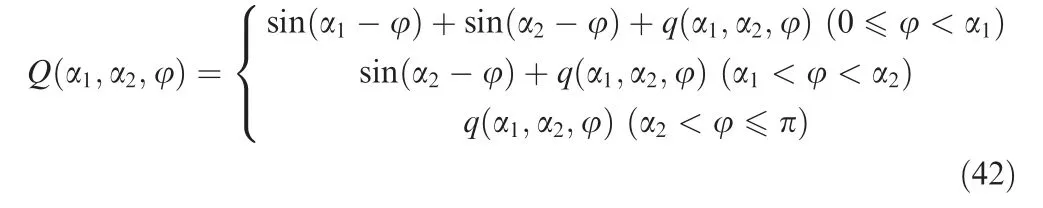
Based on Eq. (42), the changing curves of Q(α,α,φ) with respect to φ under different layouts (α, α) of guide rolls are obtained, as shown in Fig. 6. A-D, M, F and G correspond to the ring sections in Fig. 5. In Fig. 6(a), α= 60° while αvaries from 105° to 165°. When α= 105°, 120° and 135°,seven extreme points of sections A,B,C,D,M,F and G exist.When α= 150° and 165°, the extreme point of section G between sections D and B disappears.
In Fig. 6(b), α= 120° while αvaries from 15° to 75°.When α= 15° and 30°, six extreme points of sections A, B,C, D, F and G exist. When α= 45°, 60° and 75°, a new extreme value appears at section M between sections A and C. This indicates the maximum absolute value of Q(α,α,φ)may only occur at sections A,B,C,D,M,F or G,so the plastic instability is more likely to occur at the above seven sections.
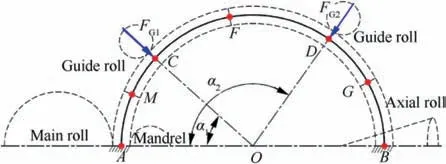
Fig. 5 Diagram for the position of ring sections A-D, M, F andG.
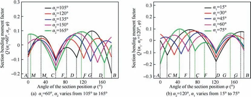
Fig. 6 Changing curves of Q(α1,α2,φ) with respect to φ under different layouts (α1, α2) of guide rolls.
To reveal the relation between the positions of guide rolls(α, α) and dangerous ring sections, Fig. 7 shows the maximum absolute value of Q(α,α,φ) (|Q|) under different αand α.Here αand αare within(0,90°]and(90°,180°),respectively. φ is from 0 to π. From Eq. (41), bigger |Q|will increase σ, promoting plastic instability of ring. When αand αare within Zones 1-4,|Q|is bigger,the plastic instability is easy to occur. When αand αare within Zones 5-6, |Q|is smaller, the plastic instability is not easy to occur.
The position angle φ of ring section corresponding to |Q|in Fig. 7 stands for the position of dangerous ring section. By calculating φ corresponding to |Q|under different αand α, the correlation between the position of guide roll and the position of dangerous ring section can be obtained,as shown in Fig. 8. φ stands for the position angle of dangerous ring section.A-D correspond to the ring sections in Fig.5.
From Fig. 8, |Q|under different αand αmainly appears at sections A-D shown in Fig.5,indicating the dangerous ring sections are A-D. When αand αare with the dark blue regions, the plastic instability may occur at section A.When αand αare with the dark red regions,the plastic instability may occur at section B.When αand αare with the light blue regions, the plastic instability may occur at section C.When αand αare with the orange regions, the plastic instability may occur at section D.
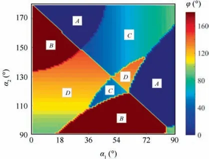
Fig. 8 Correlation between the position of guide rolls (α1, α2)and the position of dangerous ring section.
4.2.2.Correlation model of the layout of guide rolls beneficial to stability
From Fig. 7, the layout of guide rolls beneficial to stability is corresponding to a smaller |Q|. For a given αwithin(0,90°], a αcorresponding to [|Q|]can be obtained within (90°,180°). Then changing α, different αcan be obtained. By fitting the obtained data, a correlation model between αand αcan be expressed as

Fig. 7 |Q|max under different positions of guide rolls (α1, α2).
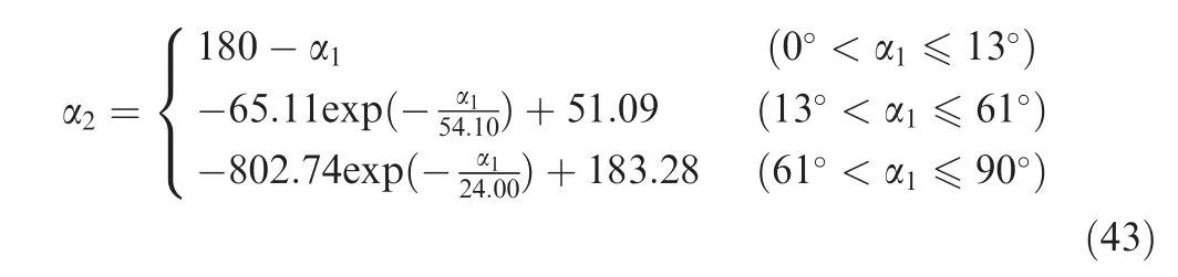
Based on Eq.(43),for an arbitrary α,the value of αcan be calculated, thus the layout of guide rolls beneficial to stability can be determined.
To further analyze the effect of αand αon plastic instability of ring,the fitting curve of αwith respect to αis plotted in Fig.9(a)and added into Fig.7(b),as shown in Fig.9(b).From Fig. 9(b), when 0° < α≤13°, |Q|increases with the increase of αand the decrease of α, the risk of plastic instability becomes bigger. When 13° < α≤61°, |Q|decreases with the increase of αand α, the risk of plastic instability becomes lower. However, when 61° < α≤ 90°, |Q|increases with the increase of αand α,the risk of plastic instability becomes bigger again.
4.2.3. Optimal layout of guide rolls
From Eq.(41),σis the minimum when|Q|has the minimum value, thus plastic instability is not easy to occur. The corresponding αand αat this time are considered to be the optimal layout of guide rolls.
From Fig. 9(b), [|Q|]occurs at α= 0° and α= 180°, which doesn’t accord with the actual assembly situations. Except this, another [|Q|]occurs as αincreases to about 61°. Then αof about 119° can be calculated by Eq.(43). Therefore, α= 61° and α= 119° may be the optimal layout of guide rolls. The corresponding value of φ also can be calculated, about φ = 119°. It means the dangerous ring section under this layout of guide rolls is section D, which is contacted with guide roll 2, as shown in Fig. 5.
The obtained layout of guide rolls (about α= 61° and α= 119°) above is just based on k= 1, but k≠1 is not considered.From Eq. (41),kmainly influences the maximum absolute value of the section bending moment factor |Q|.To determine the optimal layout of guide rolls when k≠1,the changing rule of the minimum value of |Q|([|Q|]-) under different kis investigated. Here assuming that k-∈(0,1)∪(1,10), [|Q|]is calculated for α∈[30°,90°] and α∈(90°,150°].
The changing curve of[|Q|]with respect to kis plotted in Fig. 10. When 0 < k< 1, [|Q|]decreases with the increase of k. When 1 < k< 10, [|Q|]increases with the increase of k.Therefore,the minimum value of[|Q|-]appears when kapproaches to 1.
From Fig.10,the minimum value of|Q|when k≠1 is always larger than that when k= 1. This means the optimal layout of guide rolls appears only when k=1.Therefore,the obtained layout of guide rolls(about α=61°and α=119°)in Fig.9(b)is the optimal one that is beneficial to ring stability.
4.2.4. Mathematical model of critical guide force
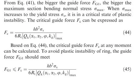
Eq. (45) gives a condition the guide force needs to satisfy for avoiding plastic instability of ring, which could provide a reference for determining the guide force during RARR process with four guide rolls.
5. Verification of plastic instability criterion
5.1. FE model of semicircular beam
To verify the plastic instability criterion, a FE model of semicircular beam with rectangular section is established,as shown in Fig.11.As instability easily occurs at the end of rolling process,the model is established based on the rolled ring size.The guide force F= F. αand αare within (0, 90°] and (90,180°], respectively.

Fig. 9 Effect of layout of guide rolls beneficial to stability on plastic instability of ring.

Fig. 10 Changing curve of [|Qk|max]min with respect to kg when kg∈(0,1)∪(1,10).
The degrees of freedom at A and B are all fixed. Fand Fare loaded at sections C and D and point to the semicircle center.The used material is 2219 aluminum alloy, whose yield strength,Young’s modulus and Poisson’s ratio are 72.03 MPa,75.2 GPa and 0.33, respectively. The semicircular beam is meshed by linear beam element B31.The simulation parameters are shown in Table 1.
5.2. Critical guide force
The critical guide force under the optimal layout of guide rolls is used to verify the plastic instability criterion. So α= 61°and α= 119° are used. F= F= 4.0 × 10N is applied on the beam. The simulative result is shown in Fig. 12. A-D correspond to the ring sections in Fig. 5. It is found that the beam produces plastic bending deformation. The maximum equivalent stress and equivalent strain both occur at section D and it is the first position to produce plastic deformation.
Fig. 13 shows the changing curves of Mises stress and equivalent plastic strain(PEEQ)with the guide force at section D. The red dashed line stands for the guide force when the material yields. The Mises stress rapidly increases with the guide force. When the guide force increases to about 3.35×10N,the Mises stress reaches the yield stress of material. Then the material produces plastic bending deformation and PEEQ begins to increase rapidly. From Eq. (44), the calculated critical guide force is about 3.21 × 10N, very close to 3.35×10N.Therefore,the critical guide force can be accurately predicted based on the developed plastic instability criterion.
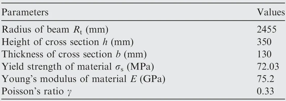
Table 1 FE simulation parameters of semicircular beam.
5.3. Section bending moment and normal stress
Based on the analysis above,the semicircular beam is in a critical state of plastic instability when F= 3.21 × 10N. The simulative results of section bending moment and normal stress at this time are showed in Fig. 14(a) and (b).
The theoretical section bending moment and normal stress can be calculated by Eqs.(37),(39)and(40).A comparison of the simulative and theoretical results of section bending moment and normal stress is made in Fig. 14(c) and (d). It can be seen the simulative results agree well with the theoretical ones. So, the section bending moment and normal stress can be accurately calculated by Eqs.(37),(39)and(40),which verifies the reliability of the developed plastic instability criterion.
5.4. Dangerous ring section position of plastic instability
The distribution of equivalent stress and strain under the optimal layout of guide rolls is shown in Fig. 15(a) and (b). It is found the Mises stress on sections A,B,C and D is bigger than that on other positions, thus the plastic instability may occur at these sections easily.The earliest position to produce plastic deformation is section D (φ = 119°), which agrees well with the result in Section 4.2.3.So the prediction for instability section position by the developed plastic instability criterion is reliable.
Based on Fig.8,the dangerous ring section position of plastic instability varies with the change of αand α. To verify this, four simulation cases are performed under different layouts of guide rolls. The simulative results are shown in Fig. 15(c)-(f). When (α, α) = {(30°, 160°), (60°, 100°), (50°,150°), (60°, 130°)}, the plastic instability occurs at sections A, B, C and D, respectively. From Fig. 8, |Q(α,α,φ)|may respectively occur at section A, section B, section C and section D when (α, α) = {(30°, 160°), (60°, 100°), (50°,150°),(60°,130°)}.Therefore,the dangerous ring section position can be accurately predicted by the developed plastic instability criterion.
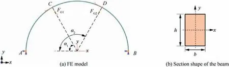
Fig. 11 FE model of semicircular beam with rectangular section.
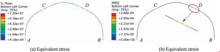
Fig. 12 Distribution of stress and strain on the beam when α1 = 61°, α2 = 119° and FG1 = FG2 = 4.0 × 10⁵ N.
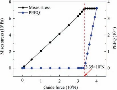
Fig. 13 Changing curves of Mises stress and equivalent plastic strain under different guide forces when α1 = 61° and α2 = 119°.
5.5. Comparison with ring stiffness model of two guide rolls in literature

where|M|is the maximum absolute value of section bending moment M(φ); Wis section modulus in bending; |Q(α,φ)|is the maximum absolute value of Q(α,φ); B and H are the axial height and radial thickness of ring, respectively; [σ]is the allowable bending stress,which is equal to yield stress σ.

Fig. 14 Simulative and theoretical results of section bending moment and normal stress when α1 = 61°, α2 = 119° and FG1 = FG2 = 3.21 × 10⁵ N.
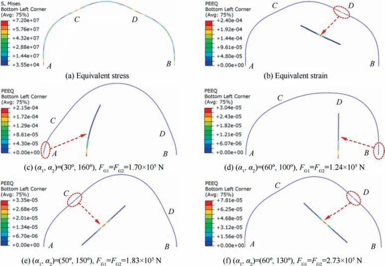
Fig. 15 Distribution of stress and strain on the beam when α1 = 61°, α2 = 119°, FG1 = FG2 = 3.21 × 10⁵ N and dangerous section positions producing plastic instability under different layouts of guide rolls.
By comparison, it is found Eqs. (46) and (47) are the same as each other. So, the plastic instability criterion of RARR with two guide rolls can be directly deduced from Eq. (41).This also proves the validity of the plastic instability criterion in this work.
6. Application of plastic instability criterion
6.1.Intelligent FE model of RARR process with four guide rolls
Based on the intelligent simulation idea of RARR with two guide rolls,this work develops an intelligent 3D coupled thermo-mechanical FE model for RARR with four guide rolls of ultra-large aluminum alloy ring under ABAQUS/Explicit environment, as shown in Fig. 16.

Fig. 16 Intelligent 3D FE model for RARR process with four guide rolls.
In the model, the guide rolls are assembled according to α= 61° and α= 119°. The material of ring is 2219 aluminum alloy. The temperature-dependent physical properties,including Yong’s modulus, specific heat, thermal conductivity and linear expansion coefficient, are derived from the reference.The constitutive relationship reported by Yangis employed to describe the plastic deformation behavior of aluminum alloy. The key technologies for FE modelling of RARR process are referenced to Guo.Other simulation parameters are listed in Table 2.
Referring to,the motions of mandrel and upper axial roll can be driven by the ring growth velocity in FE intelligent simulation. To realize the coordinated motions control of the rolls,the designed ring growth velocity curve and rolling curve in Fig. 17 are employed in this work.
In actual production, the guide roll is controlled by the hydraulic cylinder.In FE model,a stiffness-flexibility couplingmethod is used to control guide rolls.Fig.18 shows a diagram of motion control of four guide rolls corresponding to Fig.16.

Table 2 FE simulation parameters of RARR process with four guide rolls.

Fig. 17 Designed ring growth velocity curve and rolling curve in this work.
For the two guide rolls near main roll, they can swing around the hinges with the ring growth. Based on the method proposed by Zhu,the instantaneous position of the center of guide roll 1 can be determined by
where(x,z),(x,z)and(x,0)are the instantaneous coordinates of the center of guide roll 1,the fixed hinge point Pand the ring center in x direction, respectively; L is the distance between the guide roll center Gand fixed hinge point P; Rand Rare the radii of the main roll and guide roll,respectively.
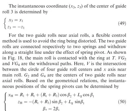
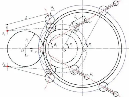
Fig. 18 Simplified diagram of motion control of guide rolls during RARR process with four guide rolls.

Table 3 Spring stiffness coefficients corresponding to different adjustment coefficients ka.

where (x, z) and (x, z) are the instantaneous coordinates of the two spring pivots,respectively;Lis the free length of spring;βis the angle between the withdrawal path VGand the x direction; βis the angle between OGand the x direction.
For the two guide rolls near axial rolls, the guide force depends on the spring stiffness and compression length of spring. When the maximum compression length Δx is given,the spring stiffness coefficient kcan be calculated by the Hooke’s law
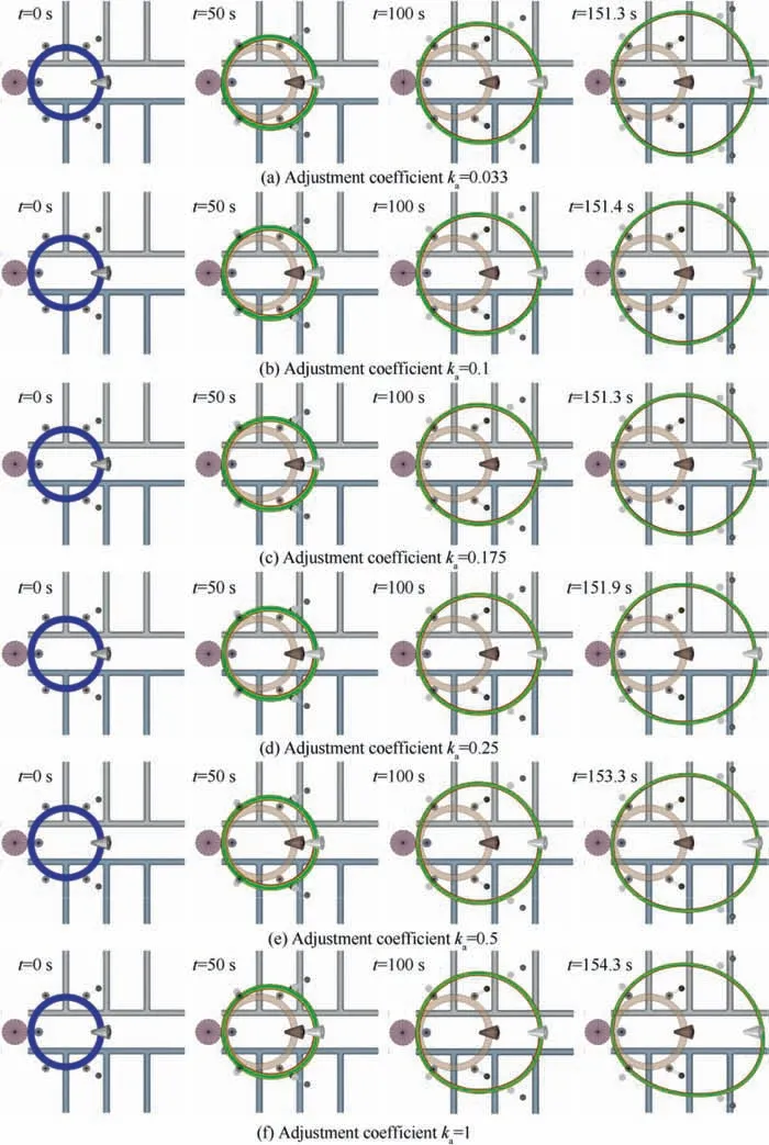
Fig. 19 Deformed contours of ring during the whole rolling process under different adjustment coefficients ka.
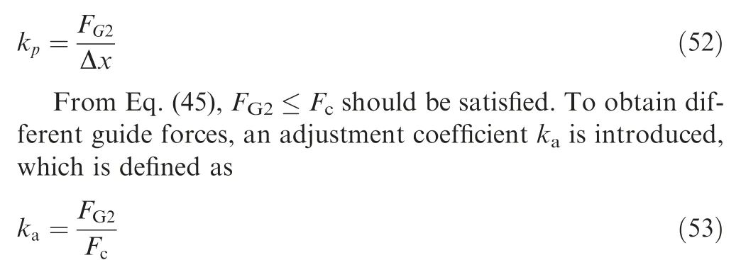
From Eqs. (45) and (53), the adjustment coefficient kranges from 0 to 1.When k=1,the guide force is the biggest and equal to the critical guide force.By adjusting k,different guide forces can be obtained. Then different kcan be calculated by Eq.(52).It means the value of kcan influence process stability and quality of ring greatly. This will be further discussed below.
6.2. Regulation of guide force in the RARR process with four guide rolls
During ring rolling process,the dimension of ring cross section decreases while the dimension of ring radius increases. Based on Eq.(44),the critical guide force Fdecreases gradually with the increase of ring radius R.To guarantee the stability of the whole rolling process,Fat the end of rolling process should be selected for regulating the guide force.From Section 4.2.3,the critical guide force Fat the end of rolling process is about 3.21 × 10N.
Assuming that the maximum compression length Δx of spring is 0.5 percent of ring’s diameter, so Δx = 5040 × 0.5% = 25.2 mm. Based on different k, the calculated spring stiffness coefficients are shown in Table 3. To determine the suitable guide force, FE simulations under different kare performed.
Fig. 19 shows the deformed contours of ring during the whole rolling process under different adjustment coefficients k. It can be seen that all the rings under different adjustment coefficients can maintain a good roundness at the early stage of rolling process.This is because the ring thickness is big and the stiffness is strong enough to maintain the geometry of ring at this stage. However, the ring thickness gradually reduces as the rolling process continues, leading to the weakness of stiffness.Especially at the end of rolling process,the ring thickness is the thinnest and the stiffness is the weakest,thus the instability of ring is most likely to occur.
From Fig.19,when k=1,the applied guide force is equal to the critical guide force, under which the ring is distorted at the end of the process. This is because the applied guide force is too large,the ring produces plastic bending instability at the end of the process.This also reflects the accuracy of the developed plastic instability criterion in a certain extent. When k= 0.5 and 0.25, small plastic bending deformation still occurs at the end of the process. When k= 0.175, 0.1 and 0.033, the applied guide force decreases greatly, thus won’t cause the plastic bending instability of ring.
Fig. 20 shows the ring center displacement in z direction(Fig. 20(a)) and the roundness error of ring during the whole rolling process (Fig. 20(b)). The black horizontal dashed line in Fig. 20(a) stands for x-axis. From Fig. 20(a), it can be seen when k=0.033 and 0.1,the oscillation amplitude of ring center is very big. This is because the applied guide force is too small and difficult to stabilize the rolling process,the ring waggles drastically. With increasing k, the applied guide force gradually increases and is enough to support the ring, making the oscillation amplitude of ring center gradually decrease,thus the forming stability gradually gets better. But when kequals to 0.25,0.5 and 1,the oscillation amplitudes of ring center increase at the end of the process because the big guide forces lead to plastic bending instability of the ring.The deformation processes for different kcan be seen in the attached GIF animations.
From Fig.20(b)it can be seen when kequals to 0.033 and 0.1, the rolled ring has good roundness, although the oscillation amplitude of ring center is very big during the process.When kequals to 0.175, the rolled ring has good roundness and the oscillation amplitude of ring center is also small thus having good stability. And when kequals to 0.25, 0.5 and 1, the roundness of the rolled ring is worse because at the end of the process the ring is distorted for big guide force.
7. Conclusions
A plastic instability criterion for the ultra-large RARR process with four guide rolls is developed in this work. Based on the criterion, the appropriate guide force and optimum layout of the guide rolls can be determined. The main conclusions are summarized as follows:

Fig. 20 Process stability and ring roundness under different adjustment coefficients ka.
(1) The radial and axial deformation regions of ring are regarded as two fixed ends at an instantaneous moment of rolling process,based on which a dynamic mechanical model for the ultra-large RARR process with four guide rolls is built.Based on the model,the calculation models of section bending moment and normal stress of ring are deduced by the force method.
(2) Considering that the section normal stress should be less than the yield stress of ring materials to ensure the steady forming of the RARR process, a plastic instability criterion for the ultra-large RARR process with four guide rolls is developed,based on which a mathematical model to calculate the critical guide force for avoiding plastic instability of ring is deduced.
(3) The influence rule of the position of the guide rolls on the dangerous ring section of plastic instability is revealed. The result shows that the dangerous ring sections are mainly located at the radial and axial deformation regions and the contact positions of guide rolls and ring. The optimal positions of the guide rolls are determined, which are about α= 61° and α= 119°.
(4) The verification of the plastic instability criterion indicate that it can be used to accurately predict the critical guide force, the section bending moment and normal stress of ring and the positions of the dangerous ring sections. Moreover, it could degrade into the case of two guide rolls validated by experiment in literature, which further confirms the validity of the developed plastic instability criterion.
(5) Intelligent simulation case studies for the RARR process with four guide rolls of ultra-large aluminum alloy ring are performed. The simulative results demonstrate that the stable forming of the RARR of ultra-large aluminum alloy ring can be effectively realized by regulating the guide force based on the developed plastic instability criterion.
The authors declare that they have no known competing financial interests or personal relationships that could have appeared to influence the work reported in this paper.
This work was supported by the National Natural Science Foundation of China (No. 51875468, 51575448) and the Research & Development Institute of Northwestern Polytechnical University in Shenzhen (JCYJ20170815162709770).