Error modeling and compensating of a novel 6-DOF aeroengine rotor docking equipment
Tinyi ZHOU, Hng GAO,*, Xunping WANG, Lun LI, Qing LIU
a Key Laboratory for Precision and Non-traditional Machining Technology of Ministry of Education, Dalian University of Technology, Dalian 116024, China
b AECC Shenyang Liming Aero-engine Co., Ltd, China
KEYWORDS Accuracy analysis;Aeroengine rotor;Docking;Error compensation;Error models;Multi-degree-of-freedom structures
Abstract In the docking process of aeroengine rotor parts, docking accuracy that indicates the gaps between the end faces is strictly required. A key issue is improving docking accuracy using automated docking equipment. In this paper, a systematic study is carried out on the error modeling and compensation of a novel six-degrees-of-freedom (6-DOF) docking equipment for aeroengine rotors. First, a new model for indicating the main indexes of docking accuracy is proposed. Then, the error model of a specially designed 6-DOF docking equipment is established based on a modified Denavit Hartenberg method with five parameters. Subsequently, two error compensation methods are proposed. Based on the above models, a docking accuracy simulation algorithm is proposed using the Monte Carlo method. Finally, verification experiments are conducted.The results show that,for the maximum values and standard deviations of the gaps between the rotor end-faces in the actual and target positions and attitudes,i.e.,main indexes that represent docking accuracy,the deviation rates between the simulation and experimental results are less than 20%.The modeling methods have referential significance.The decline rates of these values are 50-65%when using the two proposed compensation methods.The compensation methods significantly improve the docking accuracy.
1. Introduction
In the docking process of aeroengine rotor parts,gaps between the end faces, which representing the docking accuracy, are strictly requiredand have a significant influence on the coaxiality, vibration and wear performance of the aeroengine rotors. In the docking process, one part makes a multidegrees-of-freedom (DOF) docking motion while the other part remains fixed for docking stability. Traditional hoisting and vertical docking processed, which rely on manual experience, have disadvantages such as low accuracy and efficiency. Multi-DOF numerical control (NC) equipment could potentially solve these problems, and are suitable for modern horizontal assembly lines because these enable horizontal and automatic docking.
A key issue is to obtain the main indexes of the docking accuracy of rotor parts using new equipment, and ensuring that these indexes are qualified.Error modeling of new equipment has been used to evaluate the docking accuracy of rotor parts because the positioning accuracy of the mounted workpiece is determined by all the errors in the equipment. Error modeling is a time-saving method compared with repetitive docking experiments. However, for the specific case of docking aeroengine rotor parts, the works of error modeling have several challenges: First, a general model that indicates the docking error of the typical rotor parts of an aeroengine is required, and is associated with equipment errors. Second,the characterization and propagation of multiple motion errors and static errors of the relative position and attitude of different mechanisms in multi-DOF docking equipment should be clarified.Third,numerical simulation should be carried out on the basis of the error model to obtain the statistical results of quantities of docking processes, and the qualified docking rates.When the error model of a mechanism is established,precompensation of the various errors in the model can effectively improve the position and attitude accuracy of the mounted workpiece.Applying a compensation method costs less than other methods for improving accuracy, e.g., using motion parts with higher precision.In general,error modeling and compensation of docking equipment is a practical and systematic method for evaluating and improving the docking accuracy of rotor parts.
In view of the above issues, studies have been devoted to establishing models that indicate assembly accuracy when using a multi-DOF mechanism. Homogeneous matrices are widely used to indicate the transformation of the relative position and attitude errors of different parts. A homogeneous 4 × 4 matrix contains the values of 6-DOF in space, which can be used to represent the variation propagation.Geometric errors,measurement errors,etc., in the assembly can be incorporated through a homogeneous transformation model to derive the final assembly accuracy. However, there is still a lack of general geometric models to indicate the corresponding gaps that represent the docking accuracy between the end faces of typical aeroengine parts in the docking process. To establish a model indicating the errors in multi-DOF mechanisms, Denavit Hartenberg (D-H) coordinate systems and their transformation matrices are commonly used to analyze the kinematics of all motion components in a multi-DOF mechanism, this contributes toward clarifying the relationship between motion components. However, in manufacturing practice, it is difficult to make the motion axes of two adjacent motion mechanisms strictly parallel when their D-H coordinate axes are supposed to be parallel. The traditional D-H method cannot directly indicate the error. Additional D-H parameters could be helpful in improving the accuracy of the model. When the relationship between motion components is established, differential transformation matrices can be used for error analysis.Generally,differential matrices based on D-H transformation is an applicable error modeling method for multi-DOF mechanisms, while differential matrices are convenient for calculation by the algorithm. For the special multi-DOF mechanism used in the docking process,the error modeling method should be able to predict the motion error of the mechanism when the target position and attitude of the mounted workpiece are given.
On the basis of the error models,a simulation algorithm of the indexes representing the docking accuracy of seriesconnected parts is constructed.The concentricity of the revolving components in aeroengines can also be predicted using algorithms. In particular, the Monte Carlo method has achieved good result in the numerical simulation of docking accuracy by simulating a large number of random assembly processes.These efforts have contributed to the modeling and simulation of the assembly accuracy of specific types of parts. Furthermore, it is better for the simulation algorithm of docking accuracy to simulate the actual docking process in which the docking motion of the workpiece is performed with the measured fixed part as the target.
With regard to error compensation,the docking equipment designed in this study has six different DOF with high spatial accessibility. In theory, the errors of any position and attitude in the workspace can be compensated by the six motion mechanisms. The identification of error categories from the error model is the basis of compensation. Systematic errors in a mechanism are considered repeatable errors that have compensation significance. The compensation of systematic errors can be carried out by correcting NC instructions before executing the motions.Designing the compensation NC algorithm is a comprehensive work which involves the determination of errors,its association between the multi-DOF motion actuators,and the consideration of timeliness of code generation.Some studies have proposed direct compensation methods for systematic errors in multi-DOF mechanisms, which are mainly based on the error model of homogenous transformation and differential matrix derivations. However, there are numerous linear and angle errors in the multi-DOF equipment,it is difficult to identify the main errors with high sensitivity. Therefore compensation can be performed with the aim of predicting the position and attitude error of the workpiece. Comprehensive compensation of the predicted error is another effective compensation method. The compensation of NC instruction provides a new position and attitude for the workpiece,but the input of new positions and attitudes will introduce new errors. There is always a deviation between the target and actual position and attitude after executing the NC instructions. Iterative applications of specific compensation methods can further reduce deviations. However, compensation generally involves time-consuming calculations,e.g.,matrix differentiation and inversion.Reasonable compensation methods for docking equipment must provide accuracy improvement and calculation convenience.Thus,comparisons of the effects of different compensation methods are necessary.
In this paper, a systematic study on error modeling and compensation of specially designed 6-DOF docking equipment for aeroengine rotors is carried out. First, a new model for indicating the main indexes of the docking accuracy of aeroengine rotor end-faces is proposed using homogeneous transformations. Second, a novel structure of 6-DOF docking equipment is designed, and its error model is established by differential transformations based on a modified D-H method with five parameters. Then, two error compensation methods for docking equipment are proposed. Third, based on the above models, a simulation algorithm is proposed using the Monte Carlo method to simulate large quantities of docking rotors. The algorithm is consistent with the actual docking process which considers the influence of the target position and attitude determined by the fixed part. The simulation results are analyzed to compare the improvement in the main indexes of docking accuracy using different compensation methods. Finally, docking experiments are performed to validate the simulation results.
This paper is organized as follows. In Section 2, the model that indicates the docking accuracy of aeroengine rotors is proposed. In Section 3, the error modeling and compensation methods of a novel 6-DOF docking equipment are proposed.In Section 4, a simulation algorithm based on the proposed error models is constructed, and the results are analyzed. Section 5 presents a docking experiment and conclusions are drawn in Section 6.
The innovations and contributions of this paper are as follows:
(1) A new general model for indicating the docking accuracy of aeroengine rotors is proposed.
(2) A novel structure of 6-DOF docking equipment is designed, and its error model is proposed using a modified D-H method that can clarify the error propagation of the six motion mechanism in the docking equipment.
(3) Two compensation methods based on different rationales are proposed.
(4) A numerical simulation algorithm is proposed, which is consistent with actual docking processes.
(5) The simulation and experimental results show that the proposed error modeling methods are highly accurate.The proposed compensation methods significantly improve the docking accuracy. The error modeling and compensating study has referential significance for both theory and practice.
2. Modeling of the docking accuracy of aeroengine rotor parts

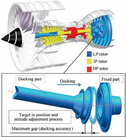
Fig. 1 Schematic of docking accuracy of typical aeroengine rotors.
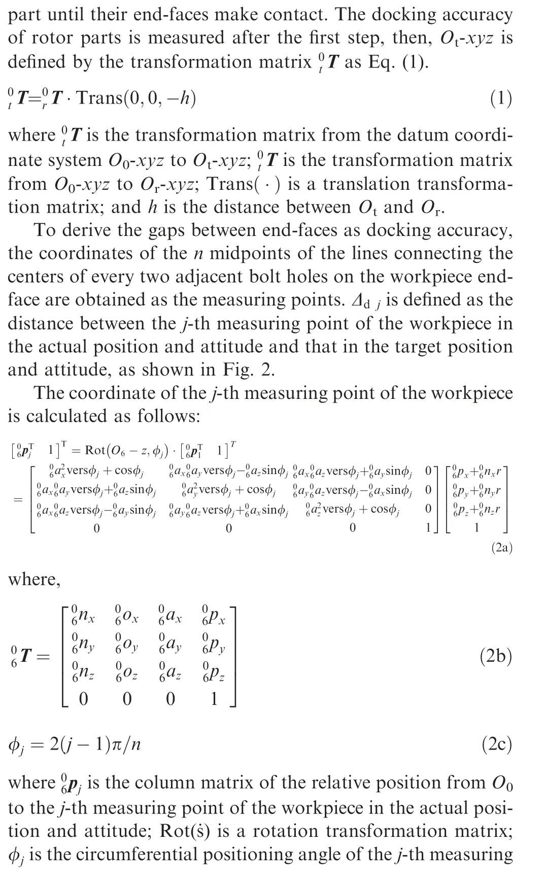
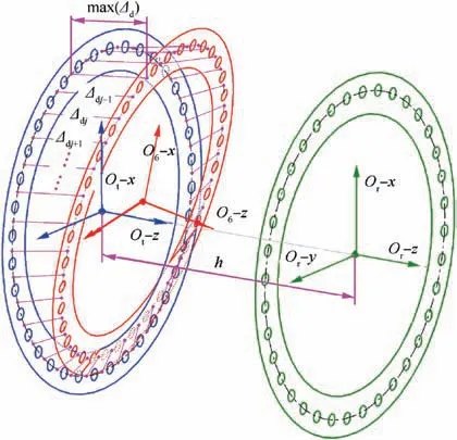
Fig. 2 Schematic of different position and attitude of rotor parts’ end-faces and corresponding gaps.

The maximum value max(Δ)and standard deviation σ(Δ)of Δare the main indexes that represent the docking accuracy.max(Δ)is the maximum gap of the corresponding measuring point pairs, the aeroengine industry has set a strict qualified value for it. σ(Δ) is the average degree of deviation of all the measured points relative to their target positions. A lower max(Δ) or σ(Δ) means that the docking accuracy improved.
3. Modeling and compensation of the errors of a novel structure of docking equipment
3.1. Structural design of the docking equipment for aeroengine rotors
Traditional simple hoisting and vertical docking equipment are widely used for docking aeroengine rotor parts in the industry.Their disadvantages include low efficiency, low accuracy due to complex manual operations,and lack of DOF.In addition,docking in the vertical direction is difficult for workers to perform,and is no longer suitable for modern horizontal assembly lines. To solve these problems, a novel structure of 6-DOF docking equipment is designed, as shown in Fig. 3. The 6-DOF motions of the designed equipment include vertical motion(X-axis),horizontal lateral motion(Y-axis),horizontal longitudinal motion(Z-axis),yawing motion(α-axis),pitching motion (β-axis), and rolling motion (γ-axis). The equipment consists of parallel and series mechanisms to achieve all the motions with high stiffness to realize the horizontal docking of aeroengine rotor parts. By changing the upper fixtures,the equipment has broad applicability in docking shafts,disks,subassemblies, etc.
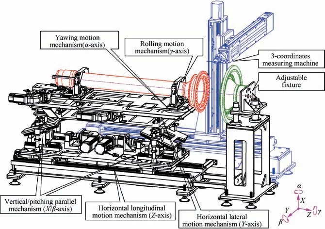
Fig. 3 Schematic of structure of the docking equipment for aeroengine rotor parts.
The Z-axis mechanism is located at the bottom base. The X/β-axis parallel mechanism is mounted on the Z-axis sliding table, and consists of two X-direction elevating mechanisms along the Z-direction. Synchronous or asynchronous driving of the two elevating mechanisms causes the upper platform to move along the X-axis or pitching around the β-axis,respectively. The Y-axis mechanism is located above the X/β-axis parallel mechanism. The α-axis mechanism is located above the Y-axis mechanism,and causes the upper platform to rotate with the α-axis bearing as the center.The rolling motion fixture is mounted above the platform,its clamping structure consists of several groups of servo rollers to rotate the workpiece around the γ-axis. An adjustable fixture is fixed next to the docking equipment,which is used to change the initial position and attitude of the fixed part.A three-axes coordinate measuring machine (CMM) is connected to the bottom base of the docking equipment. The three axes are adjusted parallel to X/Y/Z.
3.2.Error modeling of the docking equipment based on modified D-H method with five parameters
The coordinate system is set in each motion mechanism of the docking equipment using the D-H method,as shown in Fig.4.The coordinate system O-xyz is set on the bottom base of the CMM as the datum reference coordinate system. The coordinate system O-xyz is set on the guide pole of the linear bearing in the rear X-direction elevating mechanism. The coordinate system O-xyz is set on the stationary ring of the bearing,which connects the rear X-direction elevating mechanism to the upper platform. The coordinate system O-xyz is set on the Y-axis linear guide. The coordinate system O-xyz is set on the stationary ring of the α-axis yawing motion bearing.The coordinate system O-xyz is set on the clamping center of the γ-axis fixture. The coordinate system O-xyz is set on the rear end-face of the workpiece.The direction of coordinate axis O-z is defined as the motion direction of coordinate system O-xyz relative to coordinate system O-xyz. The direction of coordinate axis O-x is defined as the direction of the common normal line from coordinate axis O-z to coordinate axis O-z.If O-z intersects O-z,then the direction of O-x is defined as the direction of Oz ×Oz.
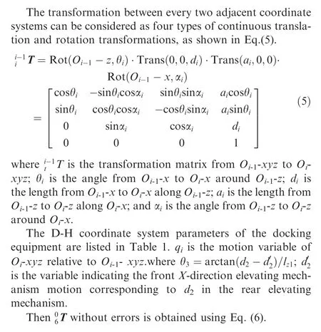

Table 1 D-H coordinate system parameters of docking equipment.
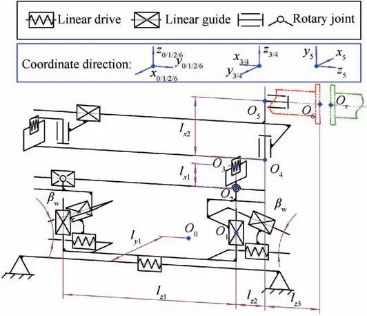
Fig. 4 Schematic of mechanism and D-H coordinate system setting of docking equipment.

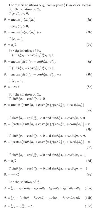
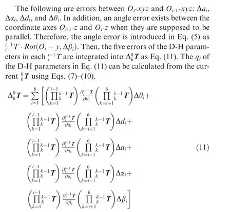

3.3. Error compensation methods of the docking equipment
3.3.1. Compensation method I: direct compensation of the systematical errors
Docking equipment errors include motion and static errors.Motion error refers to the linear displacement error or angular error in the DOF of motion of each motion mechanism.Motion errors include systematic and random errors. The motion systematic error can be obtained on the basis of multiple motion tests of one axis, then, it can be compensated directly by the corresponding servo drive system. Random motion errors generally follow the normal distribution in statistics. On the other hand,static error refers to the position and attitude error of the other five DOF of each motion mechanism relative to the adjacent mechanism. Static errors are mainly systematic errors.All systematic errors have compensation significance and their compensations are carried out by correcting the NC instructions before executing motions.
With regard to the D-H parameter errors in the docking equipment, all motion systematic errors are precompensated directly by servo drive systems. Therefore, Δqare assumed to be just random errors with normal distributions, and are mutually independent. The other D-H parameters errors are static errors,i.e.,they are systematic errors to be compensated,as shown in Table 2.
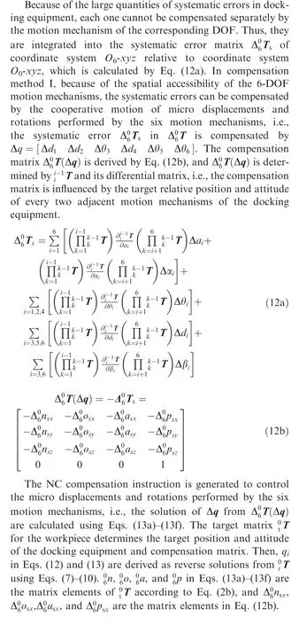

Table 2 Category setting of errors of D-H parameters.
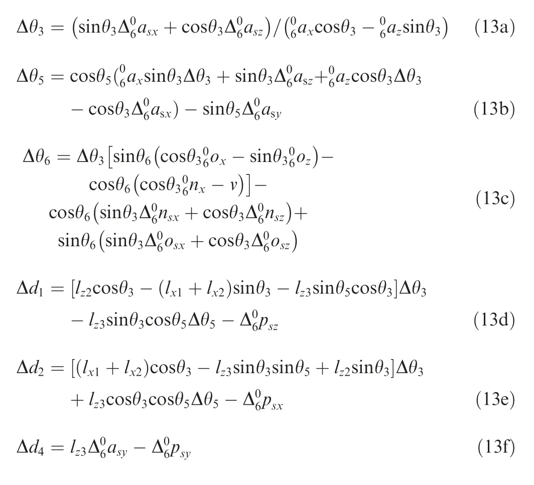
3.3.2. Compensation method II: iterative compensations based on differential transformation matrix
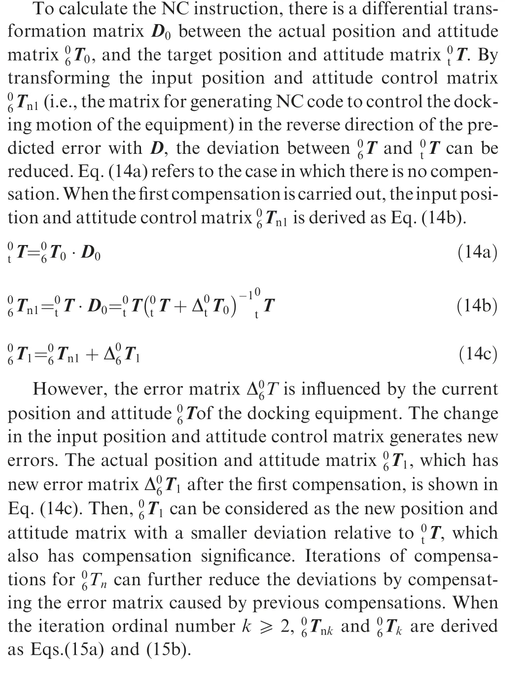
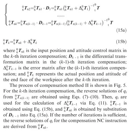
After executing the docking NC instruction,there are displacement and angular error from the target to the actual position and attitude of the workpiece. If the NC instruction on the input position and attitude of the workpiece makes the displacement and rotation relative to the target position and attitude, and the displacement and rotation have the same values but in the opposite direction of the predicted error, then the workpiece will be adjusted toward the target position and attitude.
4. Simulation of the docking accuracy based on Monte Carlo method
4.1. Construction of the simulation algorithm
The Monte Carlo method is used to simulate large quantities of docking rotors to obtain their main indexes that represent docking accuracy under different compensation methods.The flow diagram of the simulation algorithm is shown in Fig. 6.
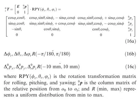
In the simulation algorithm,the simulation times M defines the total number of docking rotors,which is set to 100,000.To simulate the random condition which is consistent with the actual docking process, the initial position and attitude of the fixed part are set randomly by Eqs. (16a)-(16c).
The simulation inputs of Δq,which are transformed by linear operations based on the positioning precision of the motion drive systems in the docking equipment, are shown in Eqs. (17a)-(17e). The systematic errors of the other D-H parameters are set according to the data transformed from the accuracy measurement results of the docking equipment.
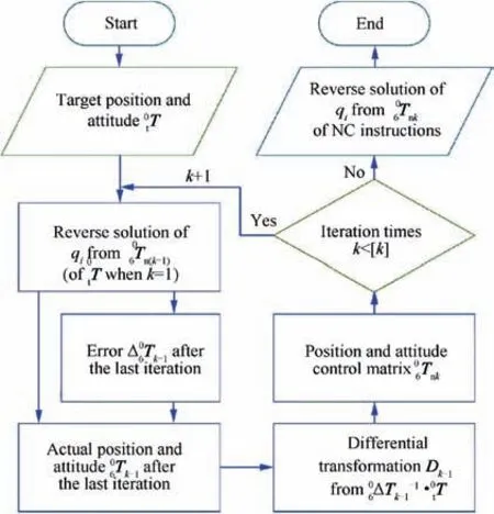
Fig. 5 Flow diagram of iterative compensation method II.
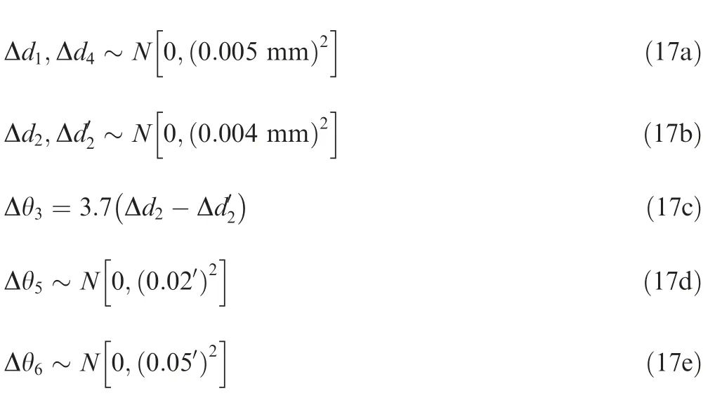
where, N (μ,σ) represents the normal distribution with μ as the mathematical expectation,and σ is the standard deviation.
The simulation has five compensation modes. No compensation is set as the reference, and ΔT is calculated using Eq.(11). When compensation method I is applied, ΔT is calculated using Eqs. (12) and (13). When compensation method II with one, two, and three iterations is applied, ΔT is calculated using Eqs. (14) and (15). The simulation results Δdof each rotor are obtained by comparingT+ΔT andt T using Eqs. (2)-(4).
4.2. Analysis of the simulation results
The outputs of the simulation algorithm, i.e., the maximum value max(Δ) and standard deviation σ(Δ) of Δ, are used to evaluate the docking accuracy.The distributions of the simulation results obtained using different compensation methods are shown in Fig. 7. All the distributions are right-skewed, as all skewness>0.The distributions are steeper than the corresponding standard normal distributions, as all kurtosis > 0.The distributions are steeper when the compensation methods are adopted.
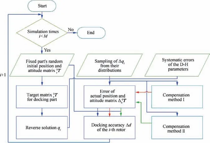
Fig. 6 Flow diagram of Monte Carlo simulation algorithm.
For compensation method I, compared with the case without compensation,the mean value and upper limit of the 95%confidence interval of max(Δ)decrease by 60.3%and 38.1%,while the mean value and the upper limit of the 95% confidence interval of σ(Δ)decrease by 60.0% and 37.9%, respectively. The industry has proposed max (Δ)≤0.08 mm as the qualified index. The qualified rates of max (Δ) are 98.7%and 54.6% with and without compensation method I,respectively.
For compensation method II with different numbers of iterations, the comparisons of the results of one, two, and three iterations with those in the case without compensation show that, the mean values of max(Δ) decrease by 51.3%, 65.4%,and 67.9%,and the upper limit of the 95%confidence interval of max(Δ) decrease by 33.9%, 44.1%, and 46.6%, respectively. The mean value of σ(Δ) decrease by 52.0%, 64.0%,and 68.0%,and the upper limit of the 95%confidence interval of σ(Δ) decrease by 34.2%, 42.1%, and 44.7%, respectively.The qualified rates of max(Δ) are 97.9%, 99.3%, and 99.5%when compensation method II with one,two,and three iterations are used, respectively.
In general,the applications of compensation methods I and II have positive effects on the key distribution statistics of max(Δ) and σ( Δ). All of the compensation methods can achieve qualified rates of max(Δ) exceeding 97%. The improvement in docking accuracy ranked from the lowest to highest is as follows: compensation method II with one iteration, compensation method I and compensation method II with two iterations.Compensation method II with three iterations shows little improvement in the docking accuracy compared with the case with two iterations.
The NC compensation instructions include time-consuming computations, e.g., matrix inversion and matrix differentiation. Additional iterations mean more computations, which affect the movement efficiency of the docking equipment.The amount of time-consuming computations and the running time of the NC instructions for different compensation methods are listed in Table 3. The average running time is tested on the following NC hardware system in docking equipment:DCCE industrial control computer iTD1015 (equipped with CPU Intel Atom CPU D525 1.8 GHz, RAM 2 GB).
The degree of improvement and the amount of computations are comprehensively considered. Compensation method II with two iterations requires 35.5% less running time than that with three iterations, and the improvement in docking accuracy is close to that with three iterations.Thus,compensation method II with two iterations is a reasonable choice.
5. Experiments
Experiments are performed to verify the simulation results.The experimental setup is illustrated in Fig. 8.
A contact probe (RENISHAW OMP 40-2) is installed in the CMM. The measurement accuracy of the CMM is 2 μm.The CMM is used to:(1) measure the initial position and attitude (i.e.,T) of the fixed part for the target matrixt T calculation. (2) Measure the initial position and attitude of the workpiece. (3) Measure the coordinates of the centers of the bolt holes of the two parts after the first step of docking motion,to obtain the two-dimensional coordinates of the measuring points on the end faces to guide the measurement path of the contact probe. (4) Measuring the coordinates of n measuring points of the fixed part and workpiece respectively.Then, Δin the experiment is derived by Eq. (18). There are four groups of docking experiments: no compensation,compensation method I, and compensation method II with 1 and 2 iterations. The number of experiments of each group is 50.The initial position and attitude(i.e.,T)of the fixed part are changed randomly by the adjustable fixture before each experiment.

Fig.9 shows the comparison of the experimental and simulation results. Limited by the number of experiment, only the mean values of max(Δ)and σ(Δ)of the experiment are considered in the comparison. The comparison shows that the deviation rates of the mean values of max(Δ)and σ (Δ)under different compensation cases are all less than 20%.The deviations of the decline rates of the mean values of max (Δ) and σ(Δ) using the same compensation method compared with the no compensation case are less than 5%. The qualified rate of max(Δ)is 98.0%when the compensation methods are used in the experiment.
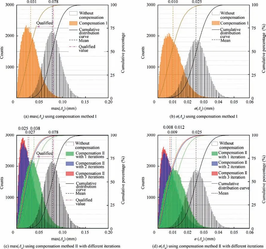
Fig. 7 Distributions of simulation outputs representing docking accuracy.

Table 3 Amount of time-consuming computations and running times of different NC compensation instructions.
The deviations are attributed to several factors that are not considered in this study: (1) The end face of the rotor part is assumed to be strictly flat in the model to indicate docking accuracy. However, flatness errors occur in the actual rotor parts. (2) The stiffness of the equipment is not considered.i.e.,the eccentric load of long workpieces in different positions and attitudes will cause different degrees of micro-deformation in the equipment. (3) In the measurement of the four types of measuring items using the CMM, there are positioning errors in the CMM and theoretical errors from the measurement methods. (4) There are errors in measuring and determining the input systematic errors of Δa,Δα,Δd,and Δθin the compensation methods. (5) In the docking experiments, the random errors Δqdo not strictly follow normal distributions and are mutually independent, as assumed in the simulation algorithm. In general, the deviations between the simulation and experimental results are acceptable.
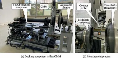
Fig. 8 Experimental setup.
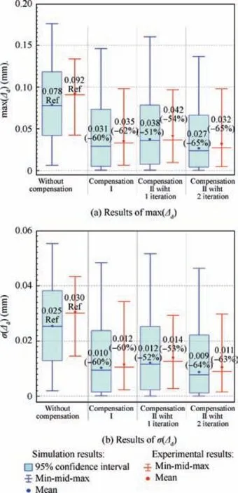
Fig. 9 Comparisons between simulation and experimental results using different compensation methods.
6. Conclusions
To improve docking accuracy using specially designed docking equipment,a systematic study on error modeling and compensation for the docking accuracy is carried out. A model indicating the main indexes of the docking accuracy of aeroengine rotor end-faces is proposed using homogeneous transformations.A new docking equipment structure for aeroengine rotors is designed, and its error model is established based on a modified D-H method and derivation of differential matrices,afterward,two error compensation methods are proposed.A Monte Carlo algorithm for simulating docking accuracy is constructed based on the proposed models.Verification experiments are then performed.The following conclusions are drawn:
(1) The mean values of the end-face maximum gap max(Δ)are 0.078, 0.031, 0.038, 0.027, and 0.025 mm, and the mean values of the standard deviation σ(Δ) are 0.025,0.010, 0.012, 0.009, and 0.008 mm for the simulation cases without compensation,with compensation method I, and with compensation method II with one, two, and three iterations, respectively.
(2) A comparison of the simulation and experimental results showed that the deviation rates of the mean values of max(Δ) and σ(Δ) under different compensation cases are all less than 20%.Thus,the modeling and simulation work is validated.
(3) The decline rates of the mean values of max(Δ) and σ(Δ) using the two proposed compensation methods are 50%-65% compared with the cases without compensation, respectively, for both the simulation and experimental results. The two proposed compensation methods significantly improve the docking accuracy and increase the qualified rates of max(Δ)to over 97%.
(4) The average running time of the NC instruction of compensation method II is 769 ms using the NC hardware system of the docking equipment,this is 35.5%less than that with three iterations. The decline rates of the mean values of max (Δ) and σ (Δ) are 60%-65%, which are close to that with three iterations. Thus, compensation method II is a reasonable choice considering its effect and amount of computation.
This research has broad prospects for realizing the precision docking of various aeroengine parts. Future work related to this study can be carried out to further improve the accuracy of models and the compensation effects. First, the geometric errors of aeroengine rotors may be integrated into the error model to indicate docking accuracy. Second, a stiffness model of the equipment may be established to predict the displacement error of the equipment under load. Third, more precise measurement methods can be proposed to obtain accurate geometric information on the docking process. Finally, hardware compensation can be integrated into the equipment to improve compensation effects.
The authors declare that they have no known competing financial interests or personal relationships that could have appeared to influence the work reported in this paper.
Acknowledgment
This research is supported by Innovative Research Group Project of the National Natural Science Foundation of China(No.51621064).
