Dynamic thermal coupling modeling and analysis of wet electro-hydrostatic actuator
Zongxia JIAO, Yanpeng LI, Tian YU, Chaofan JIANG,Ligang HUANG, Yaoxing SHANG,*
a School of Automation Science and Electrical Engineering, Beihang University, Beijing 100083, China
b Science and Technology on Aircraft Control Laboratory, Beihang University, Beijing 100083, China
c Research Institute for Frontier Science, Beihang University, 100083 Beijing, China
d Ningbo Institute of Technology, Beihang University, Ningbo 315800, China
KEYWORDS Electro-hydrostatic actuator;Hydraulic;More electric aircraft;Thermal mode;Wet motor
Abstract The electro-hydrostatic actuator (EHA) used in more electric aircraft (MEA) has been extensively studied due to its advantages of high reliability and high integration.However,this high integration results in a small heat dissipation area,leading to high-temperature problems.Generally,to reduce the temperature,a wet cooling method of using the pump leakage oil to cool the motor is adopted, which can also increase the difficulty of accurately predicting the system temperature in the early design stage.To solve this problem,a dynamic coupling thermal model of a wet EHA is proposed in this paper.In particular,the leakage oil of the pump is used as a coupling item between the electrical system and the hydraulic system.Then,an improved T-equivalent block model is proposed to address the uneven distribution of axial oil temperature inside the motor, and the control node method is applied to hydraulic system thermal modeling. Meanwhile, a dynamic coupling thermal model is developed that enables a dynamic evaluation of the wet EHA temperature.Then,experimental prototypes of wet motor and wet EHA are developed,while the temperature response of the wet motor at different rotation speeds and different loads and the temperature response of the wet EHA at no-load condition were verified experimentally at room temperature,respectively.The maximum temperature difference between the experimental and theoretical results of the wet motor as well as the experimental and theoretical results of the wet EHA is less than 8°C.These test results indicate that the dynamic coupling thermal model is valid and demonstrate that the thermal coupling modeling method proposed in this paper can provide a basis for the detailed thermal design of EHA.
1. Introduction
An electro-hydrostatic actuator (EHA) is a typical power-bywire (PBW) aircraft actuation with high integration and efficiency.It is usually composed of a direct current (DC)motor,a bidirectional pump,an actuator and an accumulator.For aircraft actuation system, EHA is widely regarded as excellent alternative to traditional hydraulic actuator because they eliminate the need for a centralized oil source, which would increase the maximum take-off weight and the survivability of the aircraft.Accordingly, it has been successfully used on the hydraulic power network of F35 military aircraft and Airbus A380 civil aircraft.
However, EHA systems face problems with concentrated‘‘hot spots” due to the lack of sufficient heat sink to absorb the heat generated by the system.Excessive temperatures can cause serious problems such as motor demagnetization,short circuits, increased system leakage and reduced reliability.Therefore, thermal design is an essential aspect in the EHA design process.
Increasing the system size of the EHA and the active loadsensitive configuration are effective measures to reduce the temperature rise in an EHA system.However, these two solutions result in an increased system mass and reduced reliability.In addition,a wet EHA is considered to be an effective configuration for reducing the system temperature. This is achieved by eliminating the shaft seal on the hydraulic pump,which allows the leakage oil to enter the motor and absorb the heat generated by the stator and rotor.This not only simplifies the configuration but also improves the reliability of the EHA.The schematic diagram of the wet EHA is shown in Fig. 1. It should be noted that because of the wet cooling method, the motor will inevitably cause additional churning power loss, which will affect the thermal response of the motor.Thus, an accurate thermal prediction of the entire oil cooling system is essential at an early stage of the design process.
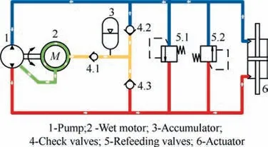
Fig. 1 Schematic diagram of wet EHA.
The generation and dissipation of heat in an EHA can be estimated by building a temperature field model of the EHA system. Numerical simulation methods used by different thermal analysis software, such as the finite element method(FEM), finite volume method (FVM) and finite difference method (FDM), are widely used in creating temperature field models. The main advantage of the FEM, FVM or FDM for solving the temperature distribution problem is that they establish the heat conduction, heat convection and heat radiation relationships among complex structures in the system,with better model accuracy. However, it has the disadvantage of excessive computational effort, and the model cannot account for the cooling effect of the oil, especially in the thermal coupling of the electrical and hydraulic systems.In addition,for thermal modeling of hydraulic systems,the nodal method is another common modeling approach. This method has high modeling accuracy and can obtain the temperature distribution of fluid and case, but the parameters used in this modeling process are not easy to obtain and there are some difficulties in the application, which need the support of experimental data.Furthermore, the lumped-parameter approach is the most common method for building temperature field models across energy domains and scales. A spatial thermal coupling model of an EHA was developed to assist in the simulation and analysis of a preliminary system.In this model,the aircraft elevator actuator and its capacitor cavity were used to explore the thermal response of the cavity under different flight conditions.The EHA was considered a stand-alone heat source in the article, and the design guidelines were given for the entire EHA and the cavity.However, there was no further study on the design of the EHA itself. To analyze the oil temperature variation behavior of an EHA system with operating conditions, a lumped parameter thermal model of an EHA hydraulic system based on the control node method was developed.This article presented a detailed thermal modeling process for key components of a hydraulic system and analyzed the thermal response of each component under different operating conditions. The results indicated that the fluid temperature varied drastically under different operating conditions.However, the effects of the motor on the EHA thermal response were not considered in the above analysis, and the effect of the oil leakage from the pump on the motor temperature was ignored.
Therefore,a dynamic thermal coupling model for wet EHA is proposed in this paper in which the temperatures of the oil inlet and outlet of the motor are used as the coupling items between the motor and the hydraulic system. The dynamic thermal coupling model can accurately predict the temperature of the wet EHA at the early stage of design, thus guiding the structural design of the EHA.
2. Thermal modeling of wet EHA
To accurately predict the temperature of each EHA component and fluid under different operating conditions,a dynamic thermal coupling model needs to be built. As shown in Fig. 2,the dynamic thermal coupling model is composed of a kinetic model and a thermodynamic model.Parameters obtained from the kinetic model, such as current, rotational speed and pressure, are transferred to the thermodynamic model. In turn,parameters obtained from the thermodynamic model, such as density and elasticity, are transferred to the kinetic model.In addition, the kinetic model of the EHA can be established by referring to Literatureand will not be introduced in this section. The difference with the method of using power bonding graph combined with FEM to analyze the thermal response of EHA introduced in Literatureis that the wet EHA thermal modeling method proposed in this paper fully considers the influence caused by leakage oil on the temperature distribution of motor and hydraulic system, and can further shorten the simulation time. The thermodynamic modeling method of a wet motor and a hydraulic system will be described in detail in the following sections.
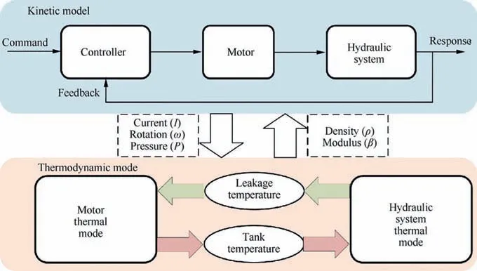
Fig. 2 Schematic of dynamic thermal model.
2.1. Thermal modeling of wet motor
To obtain the thermal dynamic response of the motor accurately, the lumped parameter model is applied. The lumped parameter model is obtained based on electromagnetic and dynamic knowledge.In addition,the T-equivalent block model proposed by Mellor is adopted since most structural components can be equivalent to a cylinder structure.In the following sections, the establishment process of the thermal motor model will be discussed in detail.
2.1.1. Derivation of motor power losses
Accurate motor loss evaluation is an essential basis for calculating a thermal motor response. The power loss of the wet motor can be divided into electrical losses and mechanical losses. Copper loss caused by the current passing through the copper conductor is an important factor affecting the temperature rise of the motor.The equation of the copper loss can be expressed as

where Pis the copper loss of the motor;nis the number of phases of the motor winding; I is the RMS value of the winding phase current; Ris the phase resistance.
The stator core loss is another important part of the electrical loss.According to the core loss mechanism,the core loss of the permanent magnet synchronous motor can be divided into hysteresis loss and eddy current loss. The expressions can be represented as

where Pis the stator core loss; kis the hysteresis loss coefficient; f is the changing frequency of the alternating magnetic field;B is the magnitude of the magnetic flux density;α is the Steinmetz coefficient and kis the eddy current loss coefficient. The rotor eddy current loss caused by the eddy current induced by the harmonic magnetic field in the rotor core and permanent magnets is always ignored.The viscous friction loss caused by the liquid viscosity occupies a large proportion of the mechanical loss,especially in the high-speed stage. For the wet motor studied in this article, we have obtained a lumped parameter model of viscous friction loss and the related results have been published in Literature.Firstly,the relationship between the oil flow state in the airgap and the rotation speed was analyzed using energy gradient theory. Then, a lumped parameter model of viscous friction loss was established using the law of conservation of momentum.Finally, the correctness of the developed lumped parameter model was verified by experimental results. The lumped parameter model can be expressed as follows.

where Pis the viscous friction loss;μ is the dynamic viscosity of the oil; ω is the rotation speed of the motor, ris the outer radius of the rotor; ris the inner radius of the stator;ρis the density of the oil at 20 °C and the pressure effect is not considered; Lis the length of the stator.
2.1.2. Description of motor thermal model
Thermal conduction and convection are the main methods of heat transfer in wet motor. The thermal resistance describing the conduction in one dimension is given as follows.

where Ris the conduction thermal resistance, Lis the length between two temperature nodes, λ is the thermal conductivity of the material, Ais the area of thermal conductivity. Due to the presence of axial coolant, the heat transfer of the wet motor requires both radial and axial heat conduction,then a two-dimensional thermal model is needed.
The T-equivalent block model, which considers the axial and radial heat transfer of the cylinder, has been widely used to construct the equivalent thermal network model of each component through the rotating electrical machine. The motor’s main solid structural components, such as the housing, stator yoke, stator teeth and windings, can be approximated as the concentric cylinder structure shown in Fig. 3.T(0)and T(L)are the nodal temperature of the two end faces in the axial direction of the concentric cylinder, T(r) and T(r)are the nodal temperature of the outer and inner surface of the concentric cylinder, Lis the length of the concentric cylinder, rand rare the outer radius and inner radius of the concentric cylinder, respectively.
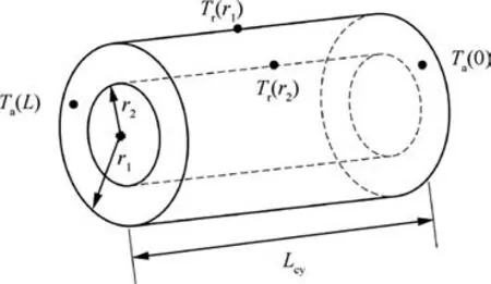
Fig. 3 General cylinder component.
According to the general cylindrical component, the thermal network,including independent radial and axial heat conduction, can be obtained as shown in Fig. 4. Tis the average temperature of the entire concentric cylinder, G is the power loss generated in the cylinder,R,R,and Rrepresent the thermal resistances of axial heat conduction, R,R, and Rare the thermal resistances of radial heat conduction. The thermal resistances can be defined as Eqs. (5)-(10),and the heat capacity of the cylinder can be expressed as Eq.(11).
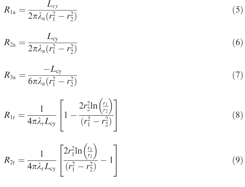
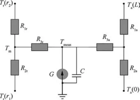
Fig. 4 Independent radial and axial thermal network.

where ρand care the density and specific heat capacity of the cylinder,respectively;λand λare the thermal conductivities in the axial and radial directions, respectively.
Therefore,the heat conduction model of each solid component can be established based on the T-equivalent block model.It should be noted that the axial flow of oil inside the air gap results in an uneven temperature distribution in the axial direction of the motor.Hence,an improved T-block thermal model is proposed to reflect the effect of oil axial flow on the thermal model. The oil in the airgap can be divided into nequal sections in the axial direction, the axial length of each section is l, and the axial velocity is v. Take three adjacent sections as the object at moment t, as shown in Fig. 5, where the temperature of each section is T,Tand T.The heat contained in section i can be given as Eq. (12).
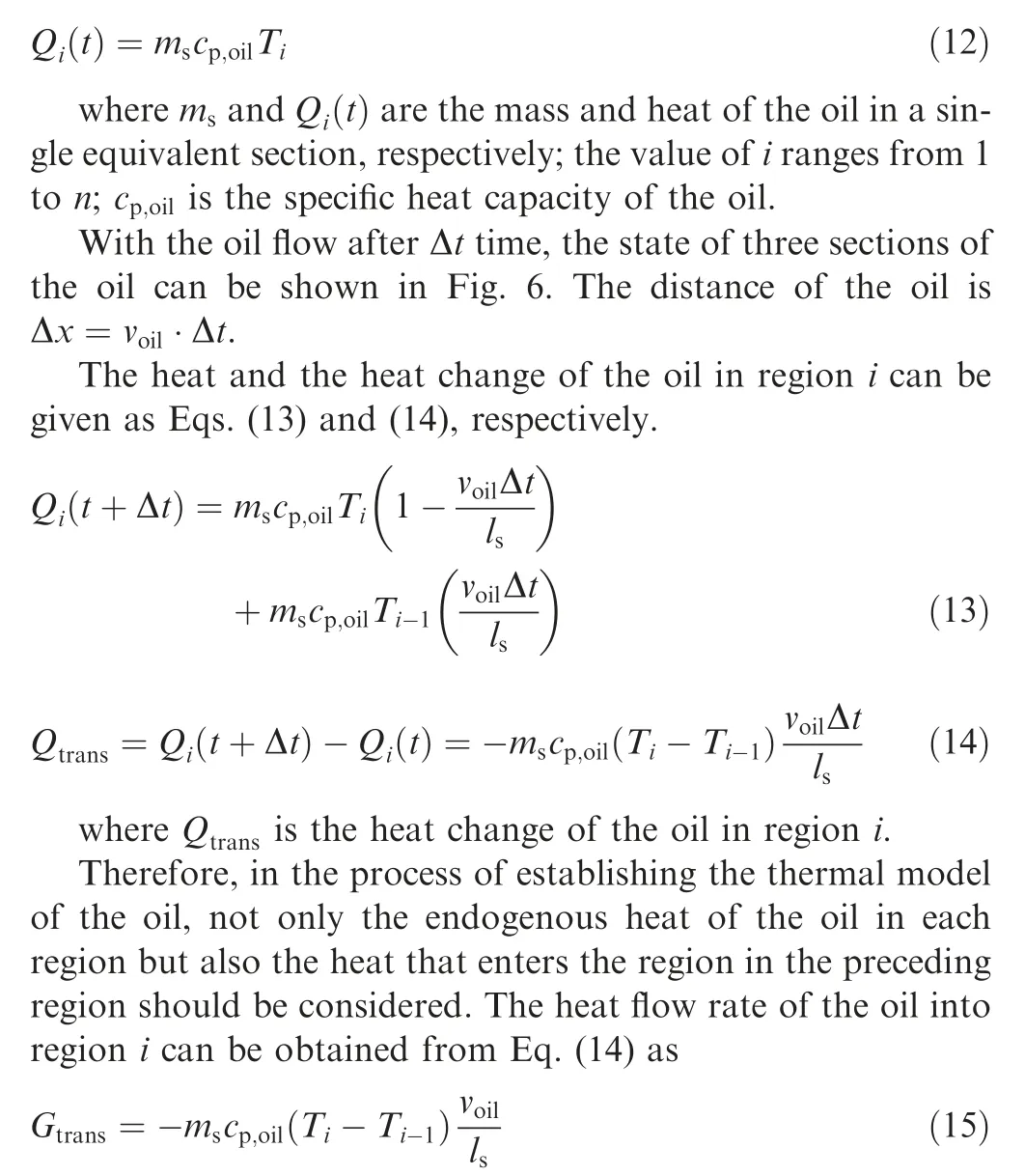
where Gis the heat flow rate of the oil into region i.
Eventually, the improved T-equivalent block model for oil in the airgap is shown in Fig. 7.
Convection heat transfer is another essential heat dissipation method for electrical motor, especially for the wet motor.The convection thermal resistance can be expressed as follows:

Fig. 5 Diagram of oil in airgap at moment t.

Fig. 6 Diagram of oil in airgap at moment (t+Δt).
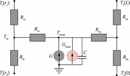
Fig. 7 Improved T-equivalent block model.

where Ris the convection thermal resistance; his the convection coefficient; Ais the contact area of the solid with the fluid. In the case of a wet motor for EHA, however, the heat generated by the motor stator and rotor is carried into the hydraulic system by the oil in the airgap. Therefore, to obtain an efficient thermal model,the convection heat transfer inside the airgap needs to be considered.
An accurate estimate of the convection coefficient between the oil in the air gap and the motor stator/rotor is necessary for a wet motor, as this is directly related to the cooling effect of the motor. In addition, the required cooling flow under extreme conditions can also be calculated, which determines the EHA pump volumetric efficiency setting. Convection heat transfer inside the airgap of the motor can be considered the sum of two parts of heat transfer: one part is the heat transfer formed by turbulent vortices, and the other part is the heat transfer caused by the turbulent axial flow.For turbulent vortices, the convection coefficient can be calculated as
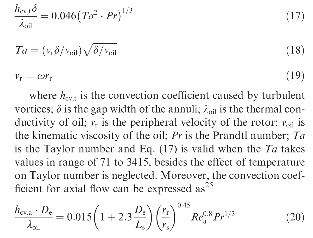

where his the convection coefficient caused by turbulent axial flow, Dis the equivalent diameter, Reis the axial Reynolds number and Eq. (20) is valid when the Retakes values in range of 380-4220, and the effect of temperature on axial Reynolds number is neglected.
Dividing the motor into five equal sections in the axial direction, the thermal network model of the wet motor can be established as shown in Fig. A1, which contains 173 nodes in total in Appendix A. For easy identification, each thermal resistance is distinguished by the same color as the motor component. In addition, the list of parameters in the wet motor simulation model is created in Appendix A.The main features of the thermal model for a wet motor can be summarized as follows.
• Radial and axial thermal resistance networks are modeled for each component of the motor.
• The effect of the inlet oil temperature on the thermal network model is considered, making it possible to establish a coupling thermal model between the wet motor and a hydraulic system.
• The influence of the axial temperature distribution of the oil inside the airgap on the thermal model is considered.
• The effect of oil axial velocity and rotation speed on the convective heat transfer coefficient is established.
2.2. Thermal modeling of hydraulic system
2.2.1. Basic modeling method
The control node method based on the first law of thermodynamics can be effectively applied to the thermal modeling of the hydraulic system.Fig. 8 shows a schematic diagram of a thermodynamic system that can be universally applied to the thermal characterization of various hydraulic components.The differential equation for the conservation of oil energy in the control node can be expressed as

where ˙E is the rate of energy in the control node, ˙mis the rate of the oil mass that enters the control node, ˙mis the rate of the oil mass that leaves the control node,hand hare the specific enthalpies that enter the control node and leave the control node, respectively. ˙Q is the rate of heat transfer and ˙W is the rate of work done by the control node.
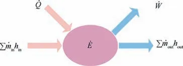
Fig. 8 Schematic diagram of control node method.
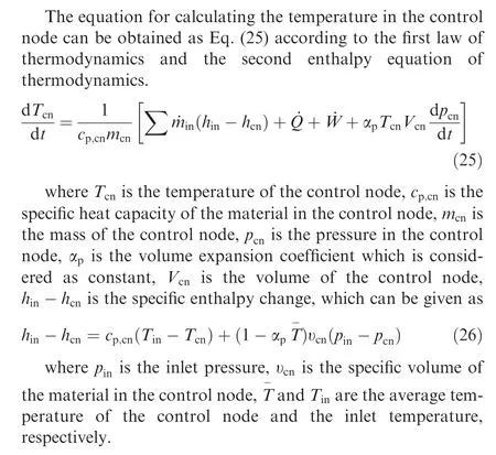
2.2.2. Thermal modeling of the pump
According to the operating principle of the hydraulic pump,as shown in Fig.9,the thermodynamic model of the pump can be divided into three fluid control nodes and a mass control node.These control nodes can be abstracted and simplified, as shown in Fig. 10.
The lower corners t, p, l, and w are used to distinguish between the pump inlet, outlet, leakage and shell control nodes. In addition, the solid arrows in the Fig. 10 represent the transfer of oil, the dashed arrows represent the transfer of heat. Therefore, the temperature changes for each control node of the pump can be obtained from Eqs.(27)-(30) as follows.
Thermal model of the pump inlet control node
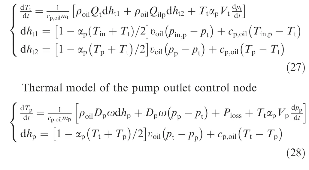

Fig. 9 Schematic diagram of hydraulic pump.
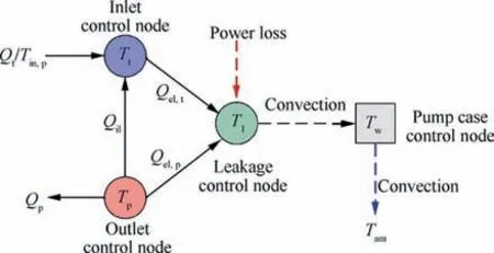
Fig. 10 Control nodes of pump.
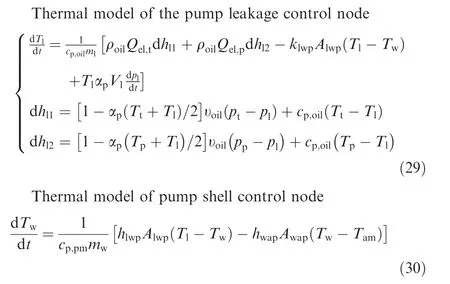
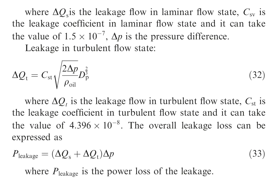
where T,T,T,and Trepresent the temperatures of each control node; Tis the oil temperature into the inlet control node, Tis the temperature of the atmosphere; m, m, m,and mare the masses of the control nodes; V, V, Vare the volumes of the control nodes; p, p, pare the pressures of the control nodes, pis the pressure into the inlet control node; Qis the inlet flow rate, Qis the internal leakage flow rate, Qand Qare the external leakage of the pump;dh,dh,dh,dhand dhare the specific enthalpy change of each control node; Dis the displacement of the pump; his the convective heat transfer coefficient of the contact surface between the shell and the oil;his the convective heat transfer coefficients of the contact surface between the shell and the air, hand hare assumed to be constants in the calculation; Ais the contact area between the shell and the oil,Ais the contact area between the shell and the air; υis the specific volume of the oil; cis the specific heat capacity of the pump; Pis the pump power loss, which includes the friction loss of the piston/slipper pair, the friction loss of the piston/cylinder pair, the friction loss of the cylinder block/-valve plate pair and the viscous friction loss in the casing filled with oil, and the calculation method of these losses can be obtained from Literature.Bearing friction loss is another form of mechanical loss,however,it is neglected due to a small proportional in this section. In addition, the oil leakage from the sealing surface of the pump can cause more serious volume loss.The volume loss can be divided into laminar flow leakage loss and turbulent flow leakage loss,and its calculation expression can be written as Eqs. (31)-(33).
Leakage in laminar flow state:

2.2.3. Thermal modeling of the actuator
The schematic diagram and thermal diagram of the actuator are shown in Figs.11 and 12,respectively.The damping effect of the inlet and outlet of the actuator cylinder is not considered in the thermal modeling of the actuator,and the friction on the inner surface of the cylinder and external leakage is ignored.
Then, the temperature equations for the oil control nodes and the shell control node are shown in Eqs. (34)-(36),respectively.
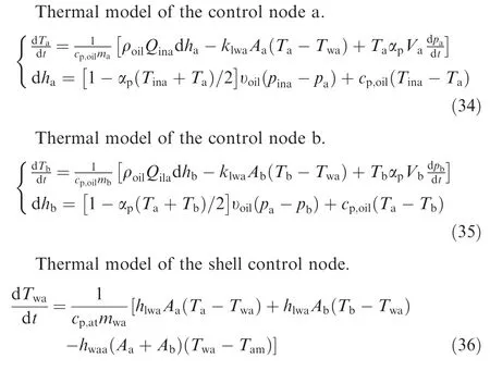
where T, T, and Trepresent the temperatures of each control volume; Tand Qare the oil temperature and flow rate into the control node a;m,m,and mare the masses of the control volumes; V, Vare the volumes of control nodes;dhand dhare the specific enthalpy change of each control node;his the convective heat transfer coefficient of the contact surface between the shell and the oil,his the convective heat transfer coefficients of the contact surface between the shell and the air, hand hare assumed to be constants in the calculation; Aand Aare the contact area between the shell and the oil; cis the specific heat capacity of the actuator material.
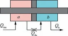
Fig. 11 Schematic diagram of actuator.
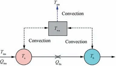
Fig. 12 Control nodes of actuator.
2.2.4. Thermal modeling of the accumulator and pipe
The thermal model of the accumulator and the pipe can be reduced to a fluid control node and a shell control node depending on their structural characteristics.Thus,the temperature variation equation can be expressed as follows.
Thermal model of the accumulator.
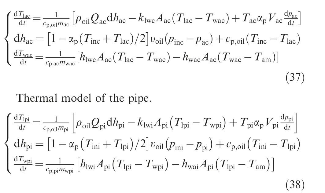
where Tand Tare the control node temperatures of the accumulator, Tand Tare the control node temperatures of the pipe, Tand Tare the oil temperatures into the accumulator and pipe; dhand dhare the specific enthalpy change of each control node;hand hare the convective heat transfer coefficients of the contact surface between the shell and the oil,hand hare the convective heat transfer coefficients of the contact surface between the shell and the air, the convective heat transfer coefficients are assumed to be constants in the calculation; Aand Aare the contact area between the shell and the oil/air;cis the specific heat capacity of accumulator;cis the specific heat capacity of the pipe.
In addition, the thermal model simulation parameters for hydraulic components are presented in Appendix B.
3. Simulation analysis
3.1. Thermal analysis of wet motor
A dynamic thermal coupling model of a wet motor is developed to analyze the thermal response of the motor under different operating conditions. Meanwhile, to verify the validity of the dynamic thermal coupling model, a corresponding MotorCAD model is built, as shown in Fig. 13, and the temperature simulation results are compared and analyzed.
Fig. 14 shows the relationship between the temperature of the winding/frame and rotation speed for a given current. It can be seen in the figure that the average winding temperature and average frame temperature increase slowly with increasing rotation speed.Meanwhile,the temperature obtained by using the lumped paragraph model(LPM)has the same trend as the data obtained from the MotorCAD simulation software,while the error is less than 3 °C.
In addition,the relationship between the temperature of the motor winding/frame and current at a constant rotation speed of 10000 r/min is shown in Fig. 15. The motor winding and case temperature increase significantly with increasing current,which means that motor winding losses are the main power loss of the motor. In addition, as seen from the comparison in the figure, the LPM-based results show good agreement with the MotorCAD simulation results. The error of the final result is less than 5 °C.
From the above simulation results,it can be concluded that the thermal model of the wet motor based on the improved Tequivalent block model is valid and can be the basis for the study of the thermal model of a wet EHA.
3.2. Thermal simulation analysis of wet EHA
According to the dynamic thermal coupling modeling principle shown in Fig. 2, the dynamic simulation model of a wet EHA can be obtained.The thermal response of a wet EHA is investigated by using the operating parameters shown in Table 1.These parameters are based on the flight rudder load requirements for a particular type of aircraft and are given in the form of a sinusoidal signal. This list of parameters does not specify the permanent load of the actuator, on the contrary, the output force capability of the actuator is verified by applying a low frequency sinusoidal load for a long time. Meanwhile,the time step is set to 0.5 ms during the simulation.
The dynamic temperature rises of the EHA motor winding and the hydraulic oil for six different operating conditions are shown in Fig.16.It can be seen in the figures that the temperature of the motor winding and the system oil temperature will gradually increase under different operating conditions.Meanwhile,it can be concluded that the system load demand,as well as the frequency, are the main factors influencing the temperature rise.
4. Experimental validation
4.1. Thermal model validation of wet motor
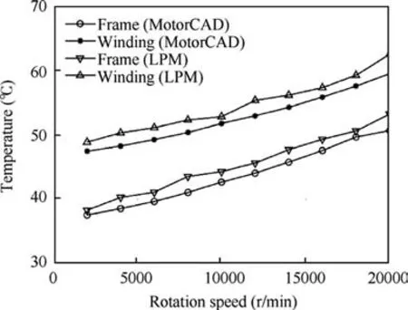
Fig. 14 Evolution of temperature with rotation speed for a current of 15 A.
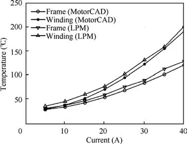
Fig. 15 Evolution of temperature with current for a rotation speed of 10,000 r/min.
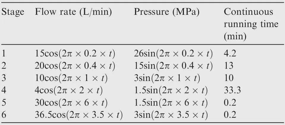
Table 1 Pressure and flow requirements for EHA system.
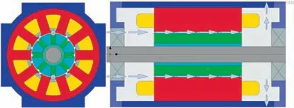
Fig. 13 MotorCAD simulation model.
To verify the validation of the proposed dynamic thermal coupling model, a test rig was designed and tested, as shown inFig.17.The test rig was composed of a wet motor,a controller with a cooling system, a dynamometer to apply an external load to the motor, and a hydraulic oil source that was used as a cooling source. Hence, the temperature response of the motor at different rotation speeds and currents could be obtained by using this test rig.
First, the relationship between the temperature and rotation speeds at a constant current was tested.Fig.18 shows the comparison curves between the theoretical results and the experimental results for the winding/frame temperature from 2000 r/min to 20000 r/min at a constant current of 15 A. It can be seen in the figure that the theoretical calculations have the same trend as the experimental results.Simultaneously,the experimental results are approximately 5 ℃higher than the theoretical results because the motor is equipped with a dynamic sealing assembly to prevent cooling oil leakage during the test, which increases the frictional losses of the motor.
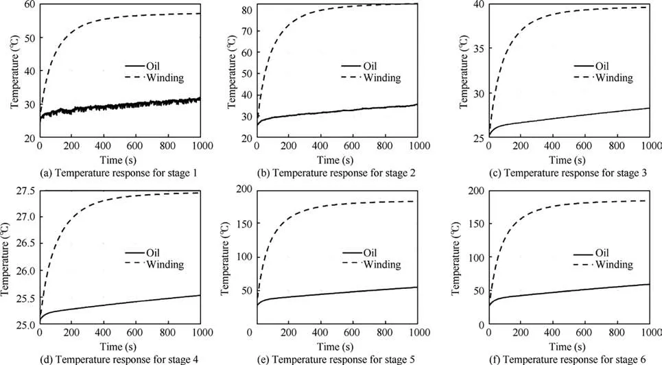
Fig. 16 Temperature response of motor windings and hydraulic oil at different stages.
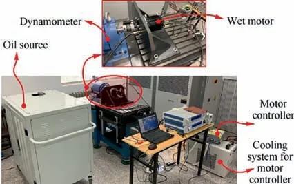
Fig. 17 Test rig for wet motor.
Furthermore,the temperature variation of the motor windings at a constant speed and different currents was tested for a wet motor. The temperature tests were carried out with variable current from 5 A to 30 A at a constant rotation speed of 10,000 r/min, as shown in Fig. 19. As shown in the figure,the test results are in good agreement with the theoretical calculations,and for the same reason,the test results are approximately 8 ℃larger than the theoretical results.
4.2. Thermal model validation of wet EHA
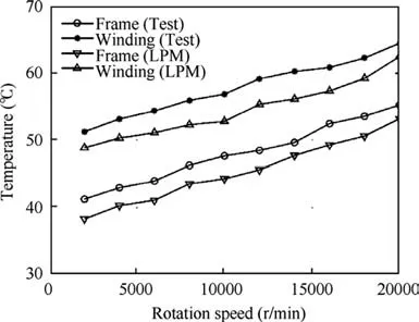
Fig. 18 Comparison curves between theoretical results and experimental results for winding and frame temperature from 2000 to 20,000 r/min at 15 A.
To verify the accuracy of the wet EHA thermal coupling model proposed in this paper, a prototype and a test rig were designed,as shown in Fig.20.The wet EHA prototype is characterized by high integration and high-power density,reaching a high-power density of 0.6 kW/kg without considering the power supplier, and the performance parameters are shown in Table 2. It integrated all the essential sensors, including the sensors to measure the temperature of the oil in the pump inlet, outlet, and leakage, the temperature of the oil in both chambers of the actuator, the temperature of the oil inside the motor, and the temperature of the motor windings and frame. In addition, pressure sensors to detect the system pressure and a linear variable differential transformer (LVDT)were also integrated.
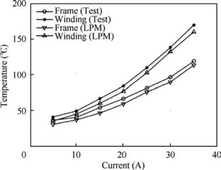
Fig. 19 Comparison curves between theoretical results and experimental results for winding and frame temperature from 5A to 35A at 10,000 r/min.
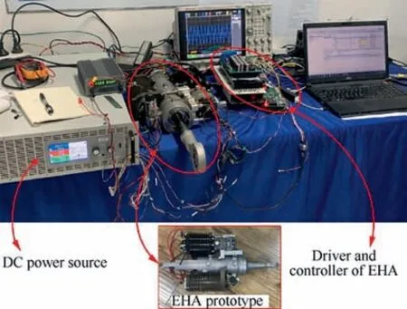
Fig. 20 Test rig for wet EHA.
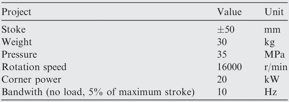
Table 2 EHA system parameters.
Due to the limitation of the experimental conditions, the temperature response of the EHA can only be experimentally verified for the no-load condition at room temperature. However, this experiment can also verify the correctness of the dynamic coupling thermal model to a certain extent. The flow requirements for stage 6 in Table 1 were used as an input to the test, and the pressure instruction was set to 0. In the experiment, a sine position response test was applied and the position command signal of the actuator can be derived from the system flow demand and combined with the parameters of the actuator cylinder. Fig. 21 shows the comparisons between the tested and theoretical results for the dynamic temperature of the motor winding.As seen in the figure,the motor winding temperature gradually increases. More importantly, the theoretical results and the experimental results are in good agreement, and the maximum error is less than 8 ℃. The results are a good demonstration of the validity of the thermal model developed Tables A1 and A2.
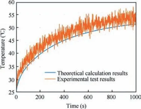
Fig. 21 Experimental and theoretical comparison graph of motor winding temperature.
5. Conclusions
A novel dynamic coupling thermal model of a wet EHA model based on the temperature coupling of pump leakage oil is proposed in this paper. The T-equivalent block model is used to construct a lumped parameter for each component of the wet motor, and an improved T-equivalent block model is developed to account for the effect of uneven axial temperature distribution of the cooling oil on the thermal response of the motor. Furthermore, a motor CAD simulation model and a wet motor temperature test bench is designed, and the temperature errors based on different rotation speeds and load are less than 8 °C, which indicates the correctness of the lumped parameter model of the wet motor. In addition, the lumped parameter model of each hydraulic component in the wet EHA is established by using the control node method.Finally, a dynamic coupled thermal model of the wet EHA model and a wet EHA prototype is designed. The maximum error between the theoretical analysis results and experimental results of wet motor winding temperature under no-load conditions and room temperature conditions is less than 8 °C,which can verify the correctness of the thermal model. Using the model,the dynamic temperature variation of EHA components under different operating conditions can be quickly and effectively predicted. The model can provide practical support for thermal design in the early design stages of wet EHA.
The authors declare that they have no known competing financial interests or personal relationships that could have appeared to influence the work reported in this paper.
This study was co-supported by the National Natural Science Foundation of China (No. 51890882) and National Key Research and Development Program of China (No.2018YFB2000702).
Appendix A. The cylindrical natural convection experimental correlations can be written as follow.
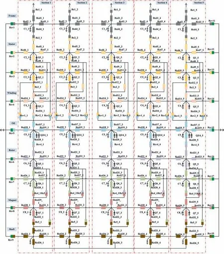
Fig. A1 Thermal network model of wet motor.

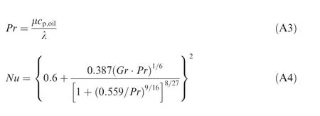
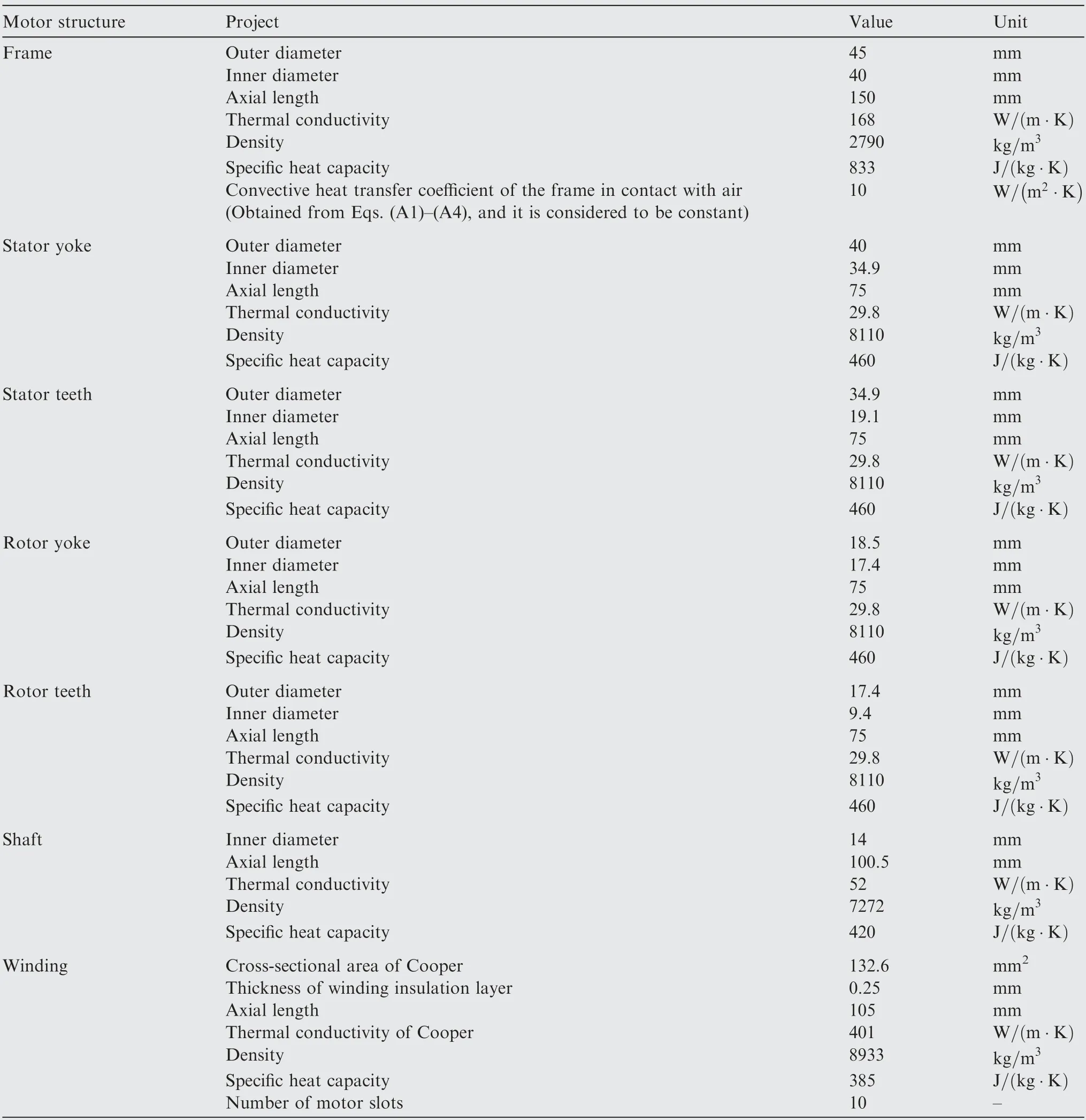
Table A1 Parameters of wet motor.
where Nu is the Nusselt Number, Gr is the Grashof number, h is the convective heat transfer coefficient, D is the characteristic length, here is the diameter of the motor frame, g is the acceleration of gravity, ΔT is the difference between the surface temperature of the solid and the temperature of the fluid. In addition, it is found that the temperature rise change has a small effect on the convection coefficient. Therefore, the convection coefficient is considered to be constant in the natural convection case.
Appendix B. The experimental correlation equation for forced convective heat transfer in a cylinder can be expressed as follows.

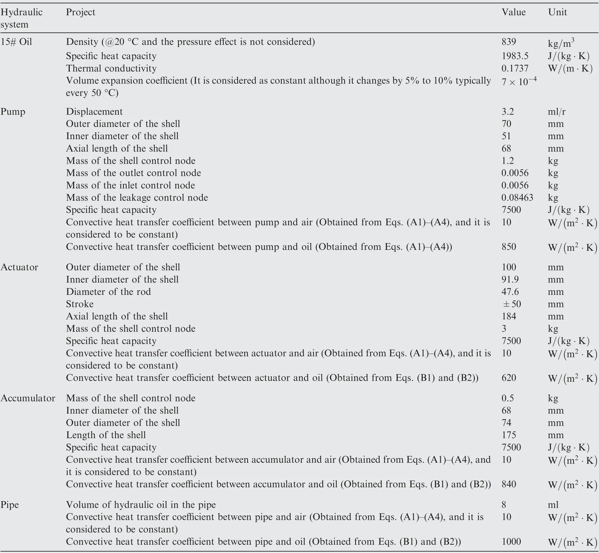
Table B1 Parameters of hydraulic system.
where cis the coefficient of fluid friction inside the hollow cylinder, Re is the Reynolds number.
