Autonomous mission reconstruction during the ascending flight of launch vehicles under typical propulsion system failures
Zhengyu SONG, Yin LIU, Yong HE, Cong WANG
a China Academy of Launch Vehicle Technology, Beijing 100076, China
b Beijing Institute of Astronautical Systems Engineering, Beijing 100076, China
c Beijing Aerospace Automatic Control Institute, Beijing 100854, China
KEYWORDS Autonomous mission reconstruction;Closed-loop guidance;State triggered indices;Rescue orbits;Launch vehicles
Abstract In recent years, Chinese Long March (LM) launchers have experienced several launch failures, most of which occurred in their propulsion systems, and this paper studies Autonomous Mission Reconstruction (AMRC) technology to alleviate losses due to these failures. The status of the techniques related to AMRC, including trajectory and mission planning,guidance methods,and fault tolerant technologies, are reviewed, and their features are compared, which reflect the challenges faced by AMRC technology.After a brief introduction about the failure modes of engines that can occur during flight,and the fundamentals of trajectory planning and joint optimization of the target orbit and flight path,an AMRC algorithm is proposed for geostationary transfer orbit launch missions. The algorithm evaluates the residual performance onboard, and plans new objectives and corresponding flight path by iterative guidance mode or segmented state triggered optimization methods in real-time. Three failure scenarios that have occurred during previous LM missions are simulated to check the robustness of the algorithm: imminent explosion risk of the boosters’ engines, thrust drop during the first stage of flight, and being unable to start the engine during the second stage.The payloads would fall from space according to the current design under these conditions,but they were saved with the AMRC algorithm in the simulations,which allowed the rocket to get into the target orbit as intended or the payloads were deployed in other orbits without crashing.Although spaceflight can be very unforgiving,the AMRC algorithm has the potential to avoid the total loss of a launch mission when faced with these kinds of typical failures.
1. Introduction
As launch activities proliferate across the globe, they come with increased risks of launch failures, such as the launch of LM-5/Y2,LM-7A/Y1,and LM-3B/Y71in China. Most failures occur in propulsion systems (including pressurization,and propellant feed system failures), and whether these missions could have been saved by advanced guidance and control technologies has attracted research attention.
In the cases of propulsion system failures,if no explosion or catastrophic failure occurs, the final outcomes can be divided into the following four categories: the mission is still ensured,like the launch of the GPS 2F-3 satellite by the Delta 4 rocket in Oct. 4, 2012;the mission is partially affected, i.e., only the primary payload is deployed into orbit, but the rideshare payloads are lost;the mission is aborted,but the payload is recovered, which mainly occurred during the era of NASA’s space shuttle;and finally, total loss of the rocket and payload,which is the most disruptive consequence. Looking back at the three failures suffered by China’s rockets mentioned above,the payloads all plummeted back through the Earth’s atmosphere and crashed.These setbacks incentivized Chinese scholars to carry out research to improve the Long March (LM)launchers’ tolerance to failures.
The main contribution of this paper is that an innovative algorithm is proposed to handle propulsion system failures,so as to save missions or avoid the rockets falling back from space. The features of this algorithm include: (A) A decisionmaking is implemented based on a real-time evaluation of the residual performance, i.e., if the target orbit is reachable,the Iterative Guidance Mode (IGM) is called to only plan the flight path; otherwise, the target orbit is planned by the State Triggered Indices(STI)method,as well as the flight path to the orbit. (B) IGM-based forward iterative method is used to accurately estimate the time-to-go,so as to eliminate estimation errors due to the assumption of a constant gravitation field potential. (C) Segmented STI processing is adopted to boost the mission reconstruction for a flight covering a suborbit coasting phase. (D) Innovative strategy matching with the algorithm is proposed, including: shut down an engine which is going to explode in time according to the sensed data,and compensate the thrust loss by later stages; re-start the engine that is unable to ignite if it could perform multi burns,which is equivalent to postponing the failure time and decreasing the impact of the failures; and switch from Perturbation Guidance Method (PGM) to IGM as soon as possible during nominal flight, but when the thrust drops and the target orbit is unreachable, use the STI optimization method as it is more secure.
The remainder of this paper is arranged as follows. The second section reviews the current status and challenges highlighted in related studies. In the third section, fundamental guidance methods are introduced, and the Autonomous Mission Reconstruction (AMRC) algorithm is proposed, taking the launching of Geostationary Transfer Orbit (GTO) satellites as background. In the fourth section, three typical failures are simulated to test the AMRC algorithm. The last section summarizes the results. A benchmark model of the second stage used in the paper is also provided in the Appendix A.
2. Reviews and challenges of ascent guidance control
Three types of techniques related to ascent guidance control are discussed here,including trajectory optimization,guidance methods, and fault tolerant technologies.
2.1. Trajectory optimization and mission reconstruction
Several interrelated but slightly different concepts are discussed first.
Trajectory planning: Planning the flight path to the target;for example, planning the flight path to a Low Earth Orbit(LEO), Sun Synchronous Orbit (SSO), or GTO. Interested readers are referred to the relevant literatures and the references therein, such as planning ascent path with the indirect heuristic method for a multistage launch vehicle;planning three-stage space launcher to SSO based on the Hamilton-Jacobi-Bellman (HJB) approach;and etc.
Mission planning:Planning all the mission profiles from the current state to the target destination, including partitioning the flight phases and burns, the switch conditions between phases and burns,stage separations and jettisons,and deorbiting, such as would be required for mission planning from Earth to Mars.
There is no strict boundary between trajectory planning and mission planning, and the analytical, numerical, and artificial-intelligent-based methods are widely used for trajectory or mission planning. In general, if the planning focuses only on specific flight phases, it is regarded as trajectory planning; for more complex tasks, it is more appropriate to consider it as mission planning. These strategies are usually implemented offline, especially for end-to-end planning;and the results of optimization, such as the flight path and staged terminal conditions, are used for guidance control inflight. Online trajectory planning is more adaptable to uncertainties,which has been proposed recently;but only nominal conditions were considered, and it is rarely applied in real flights due to its computational burdens on the embedded system or its violation of the convergence requirements for real flight.
Mission reconstruction (MRC): Revising the mission objectives,regulating the mission profiles and burns,and then planning accordingly.The major difference between MRC and the above two planning concepts is that the objective, or target obit for MRC needs to be optimized in real time, i.e., where and how to reach a new objective when faced with timevarying situations that differ from nominal conditions; while the target is clear and definite in trajectory or mission planning. So, new solutions should be found to deal with MRC problems.
If some alternatives are prepared in advance, they are considered a pre-set MRC; otherwise, they are considered as an AMRC. When considering the scenario where the objective has to be changed under a faulty situation and short mission interruptions are not allowed in-flight, an AMRC is urgently needed to save the mission, which lays even greater technical hurdles for online optimization. In some studies this is also called Fault Tolerance Guidance (FTG),although few studies and successful results have been published based on FTG.
2.2. Open-loop and closed-loop guidance methods
If online trajectory optimization is carried out iteratively in each control cycle, it is synonymous with guidance control.Guidance control determines how a rocket could reach the target orbit, which forms the basis of MRC. In the early days of aerospace industries, launch vehicles usually adopted Open Loop Guidance(OLG)to track the nominal trajectory,such as with PGM,which dominates flight guidance through the atmosphere, due to the constraints imposed by wind loads and the landing restrictions of any falling debris.However, it is theoretically difficult to meet multiple orbital elements simultaneously.
Use of Closed-Loop Guidance (CLG) methods is growing with the development of optimal control theory;such examples in the IGM developed for the Saturn V rocket, and PEG for the space shuttles.The performance of the IGM and PEG was analyzed and compared in Ref.15 and the higher-order terms ignored in IGM can be included by employing an iterative predictor-corrector method that can enhanced guidance performance of IGM.To run these methods on on-board computers, simplified dynamics models and constraints were adopted. The most important assumption is that the engine burns in a limited flight arc,generally no more than 15 degrees.Then,gravity is approximately constant both in amplitude and direction. An enhanced version of PEG is being developed by NASA for the SLS block IB rocket.The upgraded PEG could adapt an extended burn time for the exploration upper stage (from 10 to 17-20 minutes), and a consequently longer arc segment(from 15 to 35-50 degrees).Another optimal guidance method, OPGUID,has been reshelved as it requires additional development to achieve a flight-software-ready level.
It has been reported recently that the Russia launcher,Proton-M, realized so-called terminal guidance with a flexible control algorithm based on predictions of the terminal conditions and corrections made by the control program to eliminate divergences.In China, an iterative guidance algorithm was developed for the LM-2F launcher to meet the needs of rendezvous and docking of manned spaceflights.It was also revised for applications with more complicated and rigorous constraints,and was widely adopted from LEOs to SSOs and GTO launching missions.
However, all the existing OLG and CLG methods cannot effectively handle propulsion system failures, because a target orbit should be determined beforehand for these methods.
2.3. Challenges to handling abnormal engine operation
In this section, these challenges are reviewed from academic and industrial perspectives. Fault tolerant control (FTC) has been widely studied in academic works,where stability is maintained firstly which allows the mission to continue. The faulty situations lie in non-redundant and over-actuated systems,such as actuators, and control surfaces; and the recovery strategies are mostly related to control reallocation.However, under propulsion system failures, a stable flight by FTC cannot ensure the rocket entering into the prescribed target orbit, and it may be necessary to change the mission’s objectives and put the payload into a rescue orbit, otherwise it will fall out of space due to the velocity loss.
An STI-based method is proposed first to save an LEO mission,which could be considered as a FTG technology, but processing of the coasting phase is not involved.Russia experts pointed out that new-generation control algorithms should be advanced towards intellectualization to enable higher resistance to disturbances and failures, which may be realized by the real-time Adaptive Optimal Guidance Algorithm(AOGA).It has evolved from the ASTER software package developed at The Zhukovsky Central AeroHydrodynamic Institute,and adopts the modified Newton method and the principle of local extremal selection.It could have saved the failed launch of the Glonass-M satellites in December,2010had it been adopted at that time, but no online objective-change decision making was discussed in their simulations.
From the industrial viewpoint,an engine-out capability was once considered a key requirement for NASA’s launchers.Falcon 9 was also reported to have an engine-out ability.The decision to always put mission success before booster recovery in Falcon 9 mission would extend the booster’s burn time needed to achieve a landing to make up for any velocity losses caused by a failure.However, the engine-out (shut down) capability could only be considered when the rockets’performance margin is sufficient even if one engine fails.Indeed, CLG methods such as IGM could re-plan the trajectory under this condition; this can be seen from the rescued failures mentioned above in Section 1. Another example is the launch of the Egyptsat-A satellite in February, 2019.The Soyuz-2-1b/Fregat-M launch vehicle ended up on a trajectory with a perigee 57 kilometers lower than planned;however,the mission was saved also because the upper stage had sufficient performance.
To handle the failures where the performance is greatly affected, NASA’s SLS Block-1B launcher is required to select a new target or abort the mission by means whereby such a decision is made to rely on offline simulations.The response strategy, the time needed to switch to an alternative and/or any predetermined backup targets all need to be uploaded into the onboard computer in advance.This strategy is not applicable to unforeseen failure states, such as thrust drop, or thrust fluctuating violently which deviates from the prior planning.
To clarify, a brief summary of the above discussion is presented in Table 1.It can be seen that it is the first time that an AMRC has been proposed to actively address propulsion system failures during multiple flight phases.
3. Fundamentals and mission reconfiguration algorithms
A review of the failures of a liquid propellant engine suggested that the possible flaws/damages on rocket engine components come from the extreme physical conditions, mechanical and chemical complexity, manufacturing, assembly, or ground handling, and etc.,So, typical failure modes categorized by the effects of theses failed components on the flight include thrust drop, explosion,unable to startup,and accidental shutdown.Parameters to check could be found via many measures,such as the gas generator pressure and temperature, turbine inlet temperature and pressure, rotation rate of the turbine pump, pressure after pump, thrust chamber pressure, etc.Any thrust drop will become evident due to its effect on the acceleration of the vehicle.
The impact of the same failure mode on MRC will not always be the same. For example, if the thrust drops due to a blockage, it could be approximately regarded that all the remaining propellant can be used; however, if thrust drop is caused by a leakage, it is very difficult to estimate the amount of residual propellant. In the following discussion, it is assumed that no leakage has occurred.
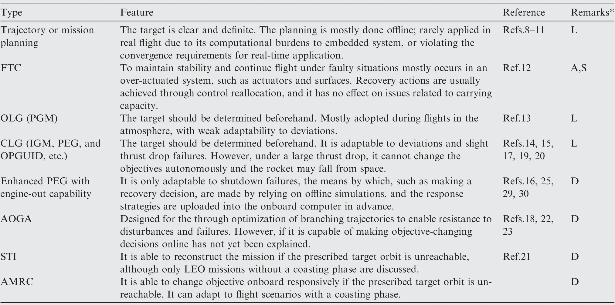
Table 1 Features of fault tolerant technologies for launchers.
3.1. Fundamentals of the guidance control method
The IGM developed for Chinese manned spaceflights, and the method of autonomous optimization of the rescue orbit under thrust dropping, are introduced, which form the basis of AMRC.
3.1.1. Iterative guidance mode
IGMs are able to plan a flight path to a determined target orbit in real time based on the maximum principle. For a detailed discussion of IGMs, the reader is referred to Ref.19; here the method is summarized as follows:
Method 1. Iterative guidance method with constant thrust,IGM.
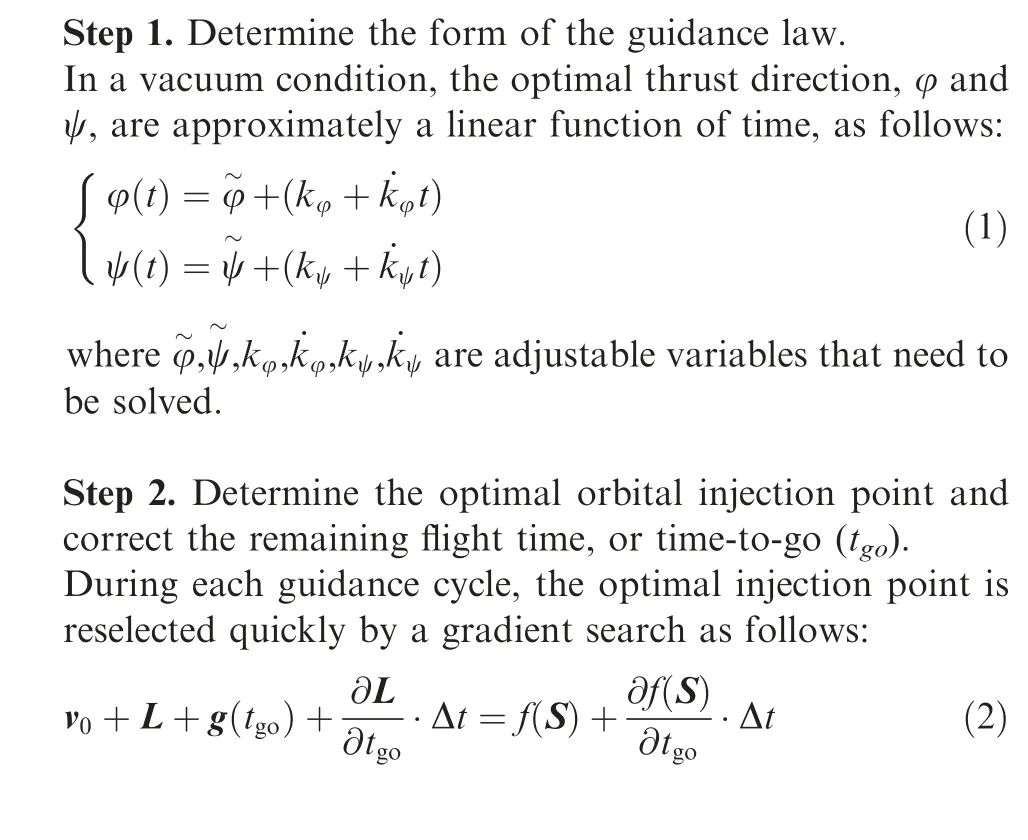
where vis the current velocity, L and S reflect the change of the velocity and position of the rocket in the remaining flight time, respectively, g(t) is the influence of gravity on the velocity during the time-to-go,Δt is the control period; and f(S) is the orbital velocity calculated by the target orbital elements,which is a function of the position,S.Eq.(2) also updates t.
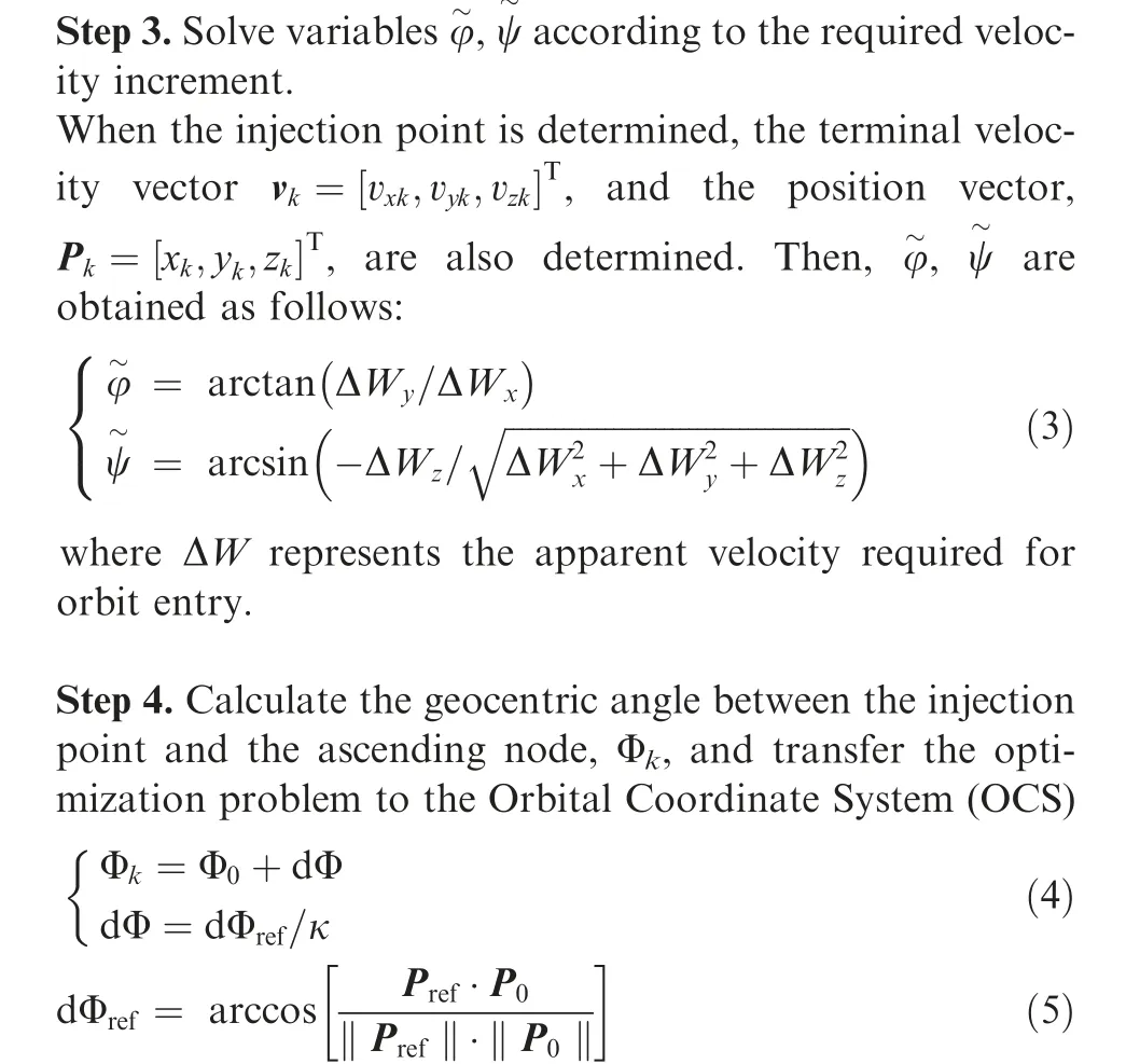
where κ refers to the percentage of thrust compared to the original thrust,and κ=1 if no failure occurs.Φis the geocentric angle between the current position and the ascending node, dΦis the angle between the injection point of the target orbit and the current position, that is, the angle between the position vector Pof the injection point and the current position vector P. The transformation matrix between the Geocentric Equatorial Coordinate System(GECS) and the OCS is shown in Eq. (6).
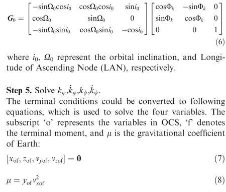
Step 6. Get the guidance command.
After solving for each variable in Eq. (1),take t=0 to get the guidance command of current cycle.
Step 7. Iterative computing
Repeat Step 2 to Step 6 in the next guidance cycle until the state variables meet the shutdown conditions.
If the thrust fluctuates, the IGM could update the equivalent specific impulse after sensing the acceleration changes, as well as simultaneously regulate the injection point and replan the trajectory. During each iteration, the initial value of t, t, should meet the following conditions:
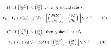
The subscript, i=x, y, z, denotes the component of the vectors. If these constraints do not hold, the scenario can be solved by Eq. (2) whereby Δt<-t, i.e., t=t+Δt<0,which will lead to divergence of the iterative calculation.
However,in the event of a large thrust drop and the target orbit becomes unreachable, it will be impossible to find any injection point in this target orbit, which violates the assumption of the IGM.This situation could be solved by the following method.
3.1.2. Optimizing the parking orbit
If the target orbit is beyond the scope of the remaining performance, the payload should be put into a parking or rescue orbit that is closest to the target orbit,called the optimal park-
ing or rescue orbit. Compared with the traditional trajectory optimization problem, the new target orbit and flight path should be jointly optimized. The approach degree of the two orbits can be quantified by the weighted sum of the square of the deviations of the five orbital elements, including the inclination i, LAN Ω, eccentricity e, semi-major axis a, and argument of perigee w, as shown in Eq. (11).
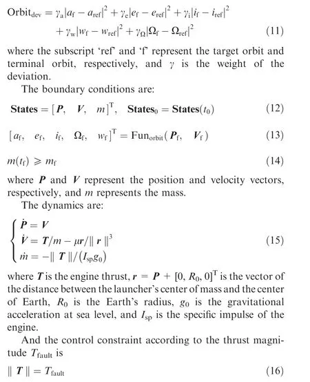
However, such weights are difficult to define. Thus, a method based on STIs was proposed to handle this problem.The starting point of using STIs is to first ensure that the rescue orbit is high enough so that the rocket does not fall back to Earth.The rescue orbit is found with the following index in the orbital plane formed at the moment of failure as
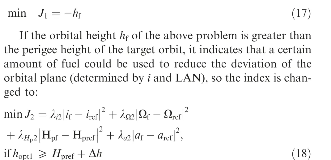
where Hrepresents the perigee height of an orbit, his the solution of Eq. (17), Δh is the tolerance height.
If the rescue orbit of the above problem is coplanar with the target orbit,the residual propellant could be used to adjust the orbital shape(determined by a,w,and e or the perigee height),so the next index is triggered as:
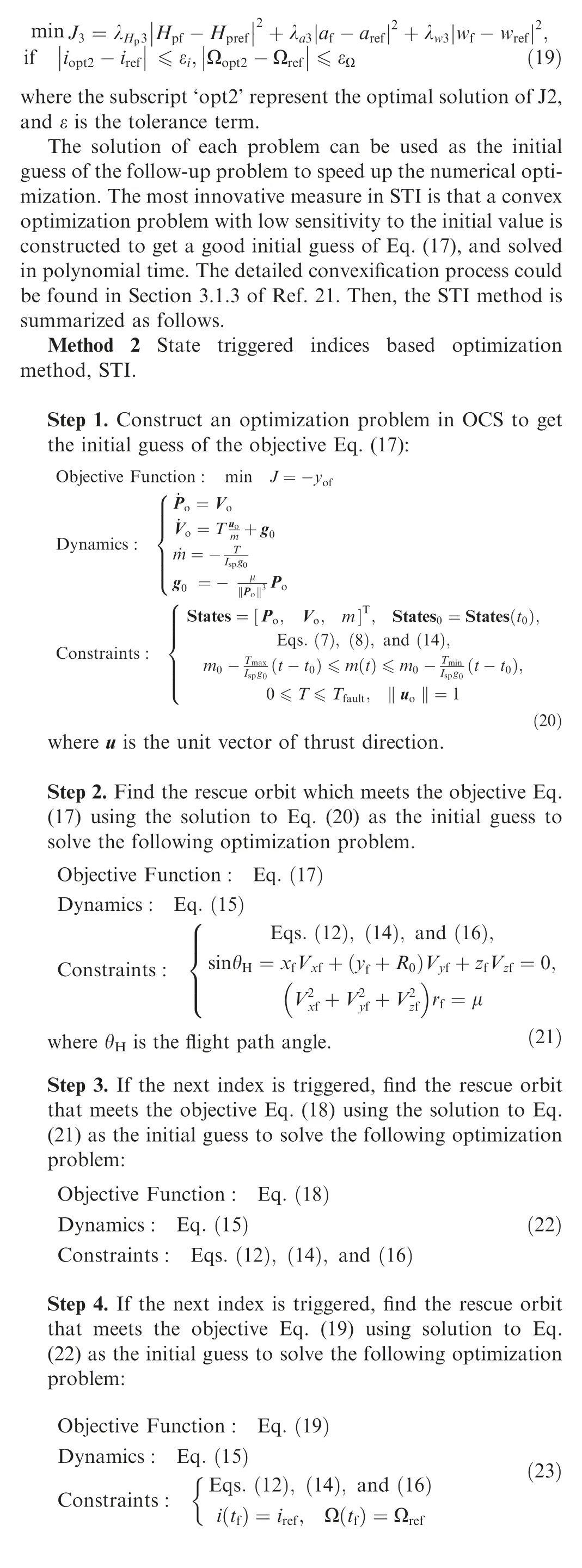
Eqs. (21)-(23) could be solved effectively by the adaptive collocation method if a reasonable initial guess is provided.So the convexification and the initial guess strategy mentioned above make the STI method suitable for real-time application. Both the new target orbit, flight path to the orbit, and time-to-go, are solved by STI. The interested reader is referred to our previous workfor solving process and simulated results.
3.2. AMRC algorithm
3.2.1. Residual performance evaluation and cutoff modes
A remaining carrying capacity evaluation is very important for AMRC.Theoretically,if the tcalculated during each control cycle is greater than the propellant exhaustion time,it indicates that the propellant will be exhausted before injection, so the orbit is unreachable.Otherwise,the rocket may enter the target orbit.
However, the assumption of a constant gravitational field in the IGM results in non-ignorable errors of tand misjudgments when the rocket is flying in a large arc. An accurate gravity model may be a solution, but this increases the complexity of the IGM and the solving time needed during normal flight. We proposed a forward iterative method known as performance evaluation based on IGM simulations(ES-IGM),which is summarized as follows:
Method 3 Performance evaluation based on simulation by IGM, ES-IGM.
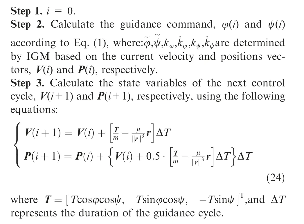
Step 4. t= (i+1)ΔT, m(i+1)=m(i)+ ˙mΔT.
Step 5. If V(i+1) and P(i+1) don’t meet the cutoff conditions, i=i+1, return to Step 2; else, tcould be used to compare with the consumption time of the remaining propellant to determine whether the target orbit is reachable.A cutoff command is usually initiated by the guidance control if one or several control quantities exceed preset thresholds, where the range (GC_Range) or Semi-Major Axis(GC_SMA) cutoff commands are mostly used. There are also backup shutdown modes if these thresholds are unable to be satisfied, including Timed Shutdown (TiS), when a prescribed flight time is met; Exhaustion Shutdown (ExS), when the propellant is about to run out (as detected by the sensors in the tanks); and Low-overload Shutdown (LoS), when the flight overload is lower than a threshold for a certain time. Backup shutdown modes usually cause significant control errors.
3.2.2. Algorithms for onboard mission re-construction
The AMRC algorithm is based on the IGM, STI, and ESIGM methods. First, the residual performance when a failure occurs is estimated by ES-IGM. If the target orbit is reachable, the IGM is called to only plan the flight path; otherwise, the target orbit and the flight path to it are planned simultaneously by the STI method. This paper takes launching a GTO satellite with a two-stage rocket as an example,where the last stage burns twice, and in between there is a timed coasting phase. This scenario is different from the LEO mission discussed in Ref. 21, so the following measures are adopted:
(1) A segmented STI processing is initiated,where the coasting orbital elements are taken as the objective of the first burn, the target orbit elements are the objective during the second burn, and in between the vehicle glides.
(2) If the coasting orbit’s perigee height is less than zero,which is more common in SSO missions, it is necessary to introduce terminal height and velocity angle constraints in rescue orbit optimization, so that when the first burn ends, the height of the rocket (h) is not lower than the safe altitude(such as 160 km)and θis greater than zero. Therefore, the second step of the STI algorithm, i.e., Eq. (21), is replaced by Eq. (25):

A revised objective is set in Eq.(25)by adding the fuel penalty term while minimizing the perigee height and semi-major axis deviations, leaving more fuel for the second burn. This helps to ensure that the rocket flies to the apogee of the coasting orbit without being affected by the atmosphere; and when arriving the apogee, the second burn is initiated.
The responses to the failures in AMRC are designed as follows:
(1)If the engine looks likely to explode, it should be shut down at once, just as the cases of Falcon 9 and Soyuz-2-1b, otherwise a blast could evolve from possibility to reality, potentially resulting in severe disasters.
(2)If the engine fails to start up,restarting is an option if it has multi-burn capability.
(3) When the rocket flies out of the atmosphere, switch from PGM to IGM as soon as possible.But if the target orbit is unreachable, call STI method at once.
Considering that a flight in the atmosphere is limited by the landing area of any jettisons, trajectory tracking control is applied during the flight of the booster and first stages regardless of whether there is a fault or not.Any mission reconstruction is then carried out during the flight of the last stage.Moreover, if a failure occurs after the rocket had entered into the prescribed coasting orbit, the performance evaluation and the rescue orbit planning are not pursued anymore; instead,use the IGM based on the prescribed target orbit elements as the terminal constraints,and deploy the payload when the second burn ends.It should be noted that the attitude is assumed to be stable under all conditions(the design of attitude control is not covered in this paper).
Then, if a failure occurs in the booster or first stages, the AMRC algorithm is employed, as shown in the following:
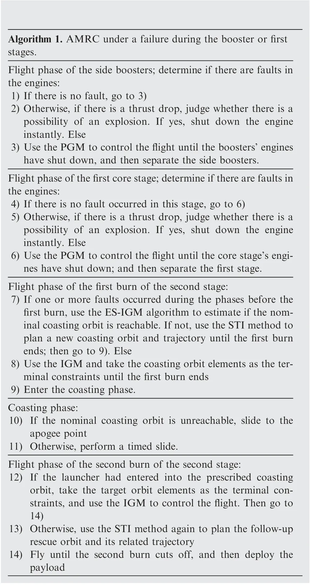
Algorithm 1. AMRC under a failure during the booster or first stages.Flight phase of the side boosters; determine if there are faults in the engines:1) If there is no fault, go to 3)2) Otherwise, if there is a thrust drop, judge whether there is a possibility of an explosion. If yes, shut down the engine instantly. Else 3) Use the PGM to control the flight until the boosters’ engines have shut down, and then separate the side boosters.Flight phase of the first core stage;determine if there are faults in the engines:4) If there is no fault occurred in this stage, go to 6)5) Otherwise, if there is a thrust drop, judge whether there is a possibility of an explosion. If yes, shut down the engine instantly. Else 6) Use the PGM to control the flight until the core stage’s engines have shut down; and then separate the first stage.Flight phase of the first burn of the second stage:7) If one or more faults occurred during the phases before the first burn, use the ES-IGM algorithm to estimate if the nominal coasting orbit is reachable.If not,use the STI method to plan a new coasting orbit and trajectory until the first burn ends; then go to 9). Else 8) Use the IGM and take the coasting orbit elements as the terminal constraints until the first burn ends 9) Enter the coasting phase.Coasting phase:10) If the nominal coasting orbit is unreachable, slide to the apogee point 11) Otherwise, perform a timed slide.Flight phase of the second burn of the second stage:12) If the launcher had entered into the prescribed coasting orbit, take the target orbit elements as the terminal constraints, and use the IGM to control the flight. Then go to 14)13) Otherwise, use the STI method again to plan the follow-up rescue orbit and its related trajectory 14) Fly until the second burn cuts off, and then deploy the payload
If a failure occurs during the second stage,the AMRC algorithm is used, as shown in the following:
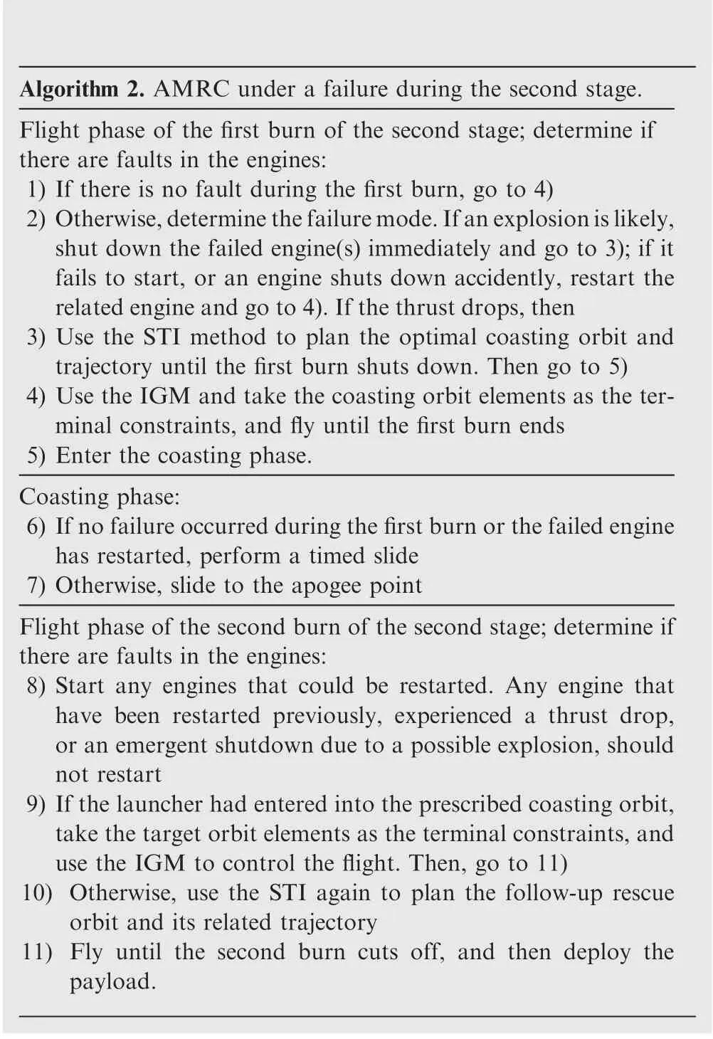
Algorithm 2. AMRC under a failure during the second stage.Flight phase of the first burn of the second stage; determine if there are faults in the engines:1) If there is no fault during the first burn, go to 4)2) Otherwise,determine the failure mode.If an explosion is likely,shut down the failed engine(s) immediately and go to 3); if it fails to start, or an engine shuts down accidently, restart the related engine and go to 4).If the thrust drops,then 3) Use the STI method to plan the optimal coasting orbit and trajectory until the first burn shuts down. Then go to 5)4) Use the IGM and take the coasting orbit elements as the terminal constraints, and fly until the first burn ends 5) Enter the coasting phase.Coasting phase:6) If no failure occurred during the first burn or the failed engine has restarted, perform a timed slide 7) Otherwise, slide to the apogee point Flight phase of the second burn of the second stage;determine if there are faults in the engines:8) Start any engines that could be restarted. Any engine that have been restarted previously, experienced a thrust drop,or an emergent shutdown due to a possible explosion,should not restart 9) If the launcher had entered into the prescribed coasting orbit,take the target orbit elements as the terminal constraints,and use the IGM to control the flight. Then, go to 11)10) Otherwise, use the STI again to plan the follow-up rescue orbit and its related trajectory 11) Fly until the second burn cuts off, and then deploy the payload.
4. Simulations and discussion
4.1. Problem description
In the following discussion, the target orbit is a 200 km (perigee height)×34902 km (apogee height) elliptical orbit. The failure cases are assumed to occur during the booster,and first and second stages, respectively. The GC_Range cutoff or ExS shutdown mode is scheduled for the flight of the booster and first stages. The paper adopts the following conditions to simplify the discussion:
(1)The first burn of the second stage adopts the GC_SMA cutoff or TiS shutdown mode (the starting time is the separation time of the first and second stages, 400 s), and then the rocket enters a timed(720 s) coasting phase. After that, the second burn begins, which is shut down by the GC_SMA cutoff or LoS shutdown mode (LoS is equivalent to the remaining mass of fuel and oxidant, which are 59 kg or 137 kg, respectively, in the simulations. The elements of the coasting and target orbits are shown in Appendix.
(2) Only the translational equations of the second stage are considered. The model and the nominal initial states are shown in Appendix. The initial states caused by failures are provided in the following sections.
4.2. Typical failure simulations
4.2.1. Explosion risks
It is assumed that there are indications of an imminent explosion in the boosters’ engines about 150 s after liftoff. According to the current design scheme, these indications are not treated in the closed-loop control, so no measures would be taken responsively, leading to an engine explosion. Such a blast would induce unpredictable consequences, even cause damage to other cabins and stages,resulting in the rocket/payload crashing and mission loss.
According to the AMRC algorithm, the boosters’ engines shut down immediately; then, the boosters separate from the core stages. The velocity and position of the rocket when the first and second stages have separated under this scenario are no longer consistent with the nominal values, as shown in the Table 2.
ES-IGM is used to evaluate the remaining performance.Since the time of failure in this case is very close to the nominal shutdown time of the boosters, the immediate shutdown has little impact on the performance and the target orbit is still reachable, so the IGM is adopted to re-plan the flight path.
A hybrid guidance method (HGM) was also simulated to provide comparison results in Table 3, where the PGM and IGM were used during the first and second burns,respectively.As the parameters of the PGM based on the nominal states do not match the failure conditions, great injection errors are produced.
The simulated results are shown in Fig. 1, where Hrepresents the perigee height,h denotes the altitude,θ is the velocity inclination,and the dotted lines and subscript‘nom’denote the variables under nominal conditions.
The orbit injection errors of each method have been compared in Table 4.
For the HGM, the errors caused by the premature shutdown of the boosters’ engines are propagated by the PGM during the first burn, and not compensated during the second burn, resulting an error of the semi-major axis of 1345.78 km.In contrast, the errors could be eliminated by the IGM during the first burn.
4.2.2. Thrust dropping
Here, it is assumed that the thrust of one engine of the first stage drops by 85%about 180 s after liftoff.The first stage flies until ExS shutdown is triggered and departs from the second stage. The initial states of the second stage are shown in Table 5.
According to the current design scheme, HGM or IGM would be applied continuously. The shutdown modes of the second stage are summarized in Table 6.

Table 2 Initial state of the second stage after a failure occurred in the boosters.
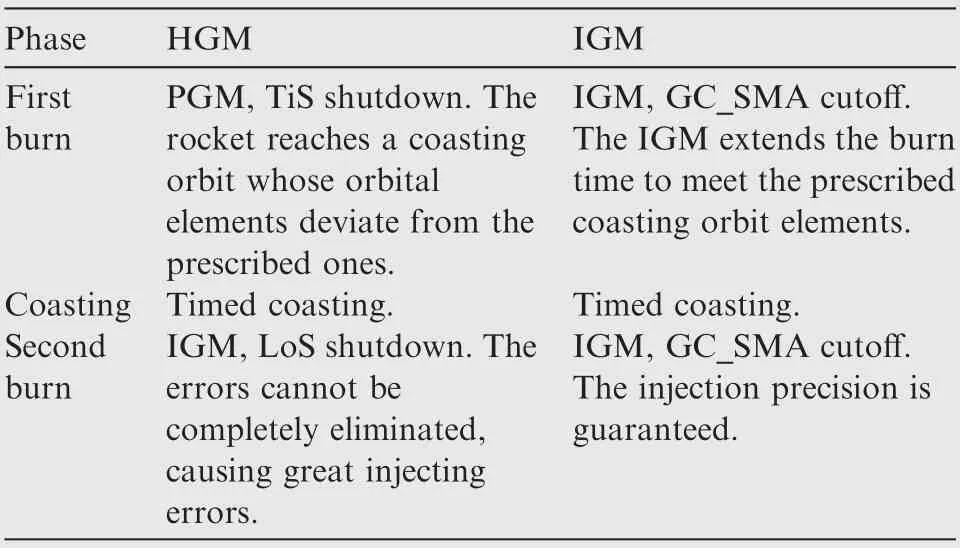
Table 3 Shutdown modes of the HGM and IGM after a failure occurred in the boosters.
The simulated results are shown in Fig.2,and it can be seen from the altitude (see red solid line of H) that the payload falls out of space during the coasting phase when using HGM.
For the IGM,the rocket is unable to reach a coasting orbit after the first burn due to the timed control (400 s), and the coasting time(720 s)is also not matched under this condition,leading to LoS shutdown of the second burn. However, the velocity and position at the shutdown moment meet the requirements of an elliptical orbit of 200 km×18,000 km,and the injection errors to the target orbit are shown in Table 7.
However, the IGM cannot guarantee that the payload will always enter into an orbit after shutdown. Suppose that the failure in this case occurs 70 s after takeoff; the initial states of the second stage are listed in Table 8.
Under this condition,TiS shutdown is triggered for the first burn,and LoS shutdown for the second burn.Finally,the payload falls back to Earth. The simulated results are shown in Fig. 3.
According to the AMRC algorithm,the STI method is used twice to solve the rescue orbit. In this case, the perigee height of the nominal coasting orbit is selected as a negative value,-770 km, Therefore, Eq. (25) is triggered. As a result, the rocket first shuts down the engines at a 160 km altitude, and enters into a coasting orbit of-767 km×478 km. After reaching the apogee of the coasting orbit, the engines are ignited a second time, and the STI method is invoked again.The rocket finally gets into a 200 km×479 km LEO orbit,as shown in Fig. 3.
The flight paths of STI in Fig. 3 are totally different from the nominal one,but the result is more acceptable than falling,as happened when using the IGM. The injection errors are shown in Table 9.
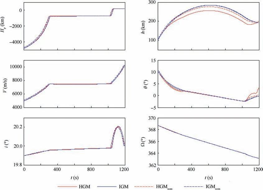
Fig. 1 Simulated results of the HGM and IGM after a failure occurred in the boosters.

Table 4 Injection accuracies of the HGM and IGM after a failure occurred in the boosters.

Table 5 Initial state of the second stage after a thrust drop failure.

Table 6 Shutdown modes of HGM and IGM after the thrust drops 180 s after liftoff.
4.2.3. Failing to start up
Here it is assumed that one engine in the second core stage fails to start up for the first burn. According to the current design scheme, the PGM or IGM would still be adopted in this situation.The initial states of the second stage are the same as the nominal conditions,and the shutdown modes of the two methods are summarized in Table 10.
The simulated results are shown in Fig.4,where we can see the rocket/payload both fall out of space by using these two methods:
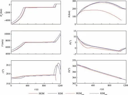
Fig. 2 Simulated results of HGM and IGM after the thrust drops 180 s after liftoff.

Table 7 Injection errors of the IGM after the thrust drops 180 s after liftoff.

Table 8 Initial state of the second stage after the thrust drops 70 s after liftoff.
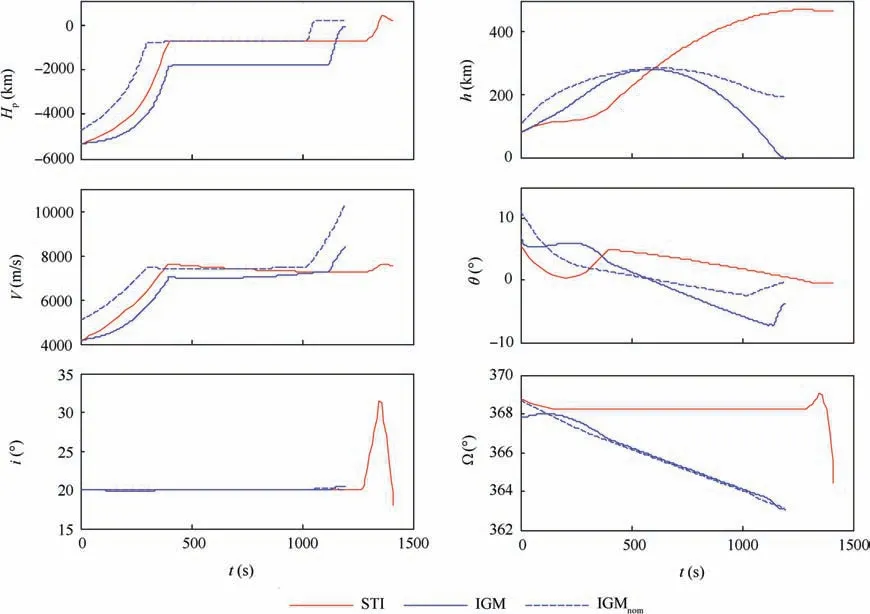
Fig. 3 Simulated results of IGM and STI method after the thrust drops 70 s after liftoff.
The main reason is that the velocity required for a coasting orbit cannot be met when the first burn finished. Meanwhile,the starting time of the second burn is not adjusted in time,and the altitude gradually drops during coasting.
However, if the AMRC algorithm is applied, the failed engine could restart at once. Then, the stage handles as expected getting through the first burn (GC_SMA cutoff)and the coasting phase. When the second burn begins, only one engine,not the formerly failed one,could restart.The simulated results are shown in Fig. 5.
It can be seen from the V,i and θ values in Fig.5 that only the second burn of the flight deviates from the nominal state,which is equivalent to postponing the failure time. Both the PGM and IGM could send the rocket into an orbit when the LoS shutdown command is triggered. The injection errors are compared in Table 11.
The IGM gives priority to adjusting the orbit plane elements,so the deviation of the orbital inclination is small.However,the LAN error is large due to the extension of the second burn time. Compared with the result of the IGM, the perigee height resulting from the PGM is too low (no more than 150 km), which is risky.
For all the simulations in Section 4, the AMRC algorithm is run on a 1 GHz embedded processor. The time spent for IGM and PGM is less than 0.1 ms,and that for ES-IGM is less than 20 ms if the ΔT is set to 1 s. It costs 0.8 s for STI to findnew target orbit and plan the flight path. The time spent for ARMC algorithm can meet the requirements of guidance control.

Table 9 Injection errors of STI method after the thrust drops 70 s after liftoff.

Table 10 Shutdown modes of PGM and IGM after a failure occurs during startup.
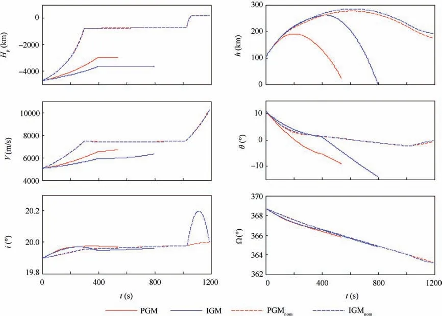
Fig. 4 Simulated results of the PGM and IGM after a failure occurs during startup.
5. Conclusions
In this paper, autonomous mission reconstruction under propulsion system faults was studied. It should be noted that online diagnoses are very challenging, and the conclusions of this paper are based on the assumption that all faults could be accurately identified.
For the three considered failures (i.e. imminent risk of explosion of the booster’s engines, thrust drop during the first stage of flight, and being unable to start the engine during the second stage),the payload would fall from space if the current design scheme was employed. However, the autonomous mission reconstruction algorithm could still ensure the mission(Section 4.2.1) or deploy the payload into a rescue orbit (Sections 4.2.2 and 4.2.3), reflecting its adaptability under these circumstances.
If the fault state is relatively stable, such as an accidental shutdown, an onboard trajectory library can be constructed through offline simulations for mission reconstruction. However, steady failure states are not guaranteed, and the statetriggered-indices-based method is more preferable when facing failures. It should be pointed out that a segmented planning based on the prescribed coasting orbit is adopted in this paper,which simplifies the online planning. However, the coasting strategy solved by end-to-end planning would be more optimal, and an effective onboard end-to-end planning, as well as the code-effectiveness of the flight software,will be the focuses of the future work.
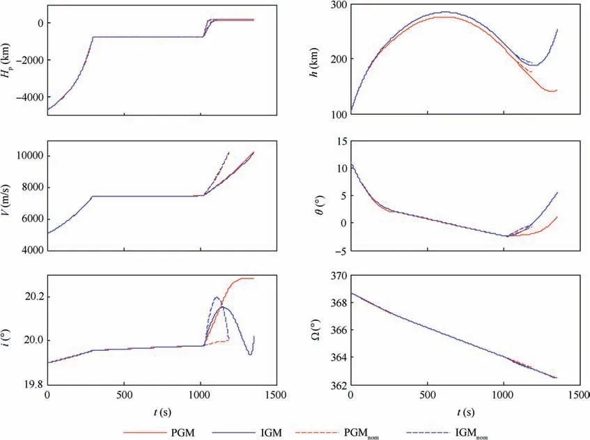
Fig. 5 Simulated results of PGM and IGM once the engine restarts.

Table 11 Injection errors of PGM and IGM once the engine restarts.
The authors declare that they have no known competing financial interests or personal relationships that could have appeared to influence the work reported in this paper.
This study was co-supported by International Academy of Astronautics (IAA) study group SG 3.32 and the National Natural Science Foundation of China (No. 61773341).
Appendix A.Benchmark rescue trajectory optimization problem
In this benchmark,we assume the vehicle’s attitude can be regulated considerably faster than its trajectory, which allows us to neglect rotational dynamics.The translational motion equation of the launcher’s second stage is described in the Launch Inertial Coordinate System (LICS), as shown in Eq. (A1):
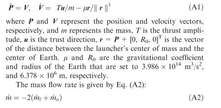
The features of the second stage are given in Table A1.
The launch site is 110°57East longitude and 19°36North latitude, and the height above sea level is set to 9.5 m, with a launch azimuth of 94.2395°. The initial states of the second stage in the LICS are presented in Table A2.
The start time of the second stage is the moment when the first and second stages depart from each other. Other important parameters used in the simulations are given below:

Table A1 Characteristics of the single engine considered in this study.

Table A2 Second stage initial states in the LICS.

Table A3 Target orbit elements and the guidance errors.

Table A4 Coasting orbit elements.
(1)The inter-stage departs in 1.3 s with a mass of 400 kg.The fairing is jettisoned in 7.3 s with a mass of 2199 kg.
(2)IGM is introduced in 17 s if it is applied during the first burn; and it is introduced in 7 s after the second burn begins.
(3)The startup and cutoff transient processes of the engines, and the precooling treatment before engine ignition, are ignored during the simulations.
The relationship between orbital elements and the launcher’s velocity and position is expressed as Eq. (A3):

where the orbital inclination i, and the longitude of ascending node Ω,determine the orbital plane;the semi-major axis a,the eccentricity e, and the argument of perigee w, determine the orbital shape.
The orbital elements of the target orbit, and the requirements of guidance control errors under nominal conditions,are shown in Table A3.Hand Hare the apogee and perigee height of the orbit, and Δ represents the deviation of the orbital parameters.
The orbital elements of the coasting orbit are shown in Table A4.
