A numerical study of segmented cooling-stream injection in supersonic film cooling
Hng NI, Mingjun WANG, Peixue JIANG, Wei PENG,d,*, Yinhi ZHU
a Institute of Nuclear and New Energy Technology, Collaborative Innovation Center of Advanced Nuclear Energy Technology,Key Laboratory of Advanced Reactor Engineering and Safety of Ministry of Education, Tsinghua University, Beijing 100084, China
b School of Nuclear Science and Technology, Xi’an Jiaotong University, Xi’an 710049, China
c Department of Energy and Power Engineering, Key Laboratory for Thermal Science and Power Engineering of Ministry of Education, Tsinghua University, Beijing 100084, China
d Tsinghua University-Zhang Jiagang Joint Institute for Hydrogen Energy and Lithium-Ion Battery Technology, Tsinghua University, Beijing 100084, China
KEYWORDS Film cooling;Mach number;Segmented injection;Shock wave;Supersonic flow
Abstract The present study proposes a segmented cooling-stream injection structure based on a certain coolant mass flow rate, and numerically investigates the effect of segmented cooling-stream injection on supersonic film cooling. The results indicate that without shock-wave impingement and with helium as the coolant, segmented cooling-stream injection can reduce the mixing between the mainstream and the cooling stream to produce better cooling performance than single injection,especially at larger coolant Mach numbers.However,with nitrogen as the coolant,the cooling effect of the segmented-injection system is very close to that of the single-injection system.Mixing at the impinging region is enhanced significantly when there is an incident shock wave.When the shock wave impinges between the two coolant inlets,segmented cooling-stream injection improves film cooling effectiveness in the midstream and downstream regions more than single injection because only part of the cooling stream undergoes the enhanced mixing effect of the shock wave.The advantage of segmented injection is reduced when the impinging region is behind the second coolant inlet.The further downstream the impinging region, the smaller the associated advantage.
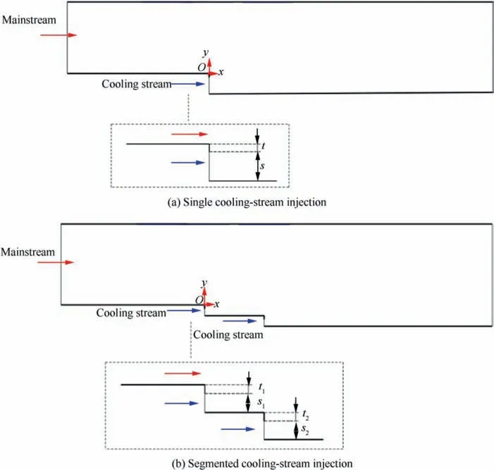
Fig. 1 Models without shock waves.
1. Introduction
Gas turbine inlet temperature increases higher and higher as a pursuit of higher efficiency and power output levels.This poses a challenge regarding thermal protection of turbine hot-section components. Film cooling is an effective approach to solving this problem.Moreover,film cooling can play an important role in aerospace technology designed to reduce heat loads and improve the performance of high-temperature components in rockets, scramjets, and hypersonic aircraft.
Film cooling can be classified into subsonic and supersonic varieties based on whether the mainstream velocity exceeds the sound speed.Numerous studies have investigated the influencing factors and flow and heat transfer characteristics in subsonic film cooling.Supersonic film cooling can achieve better cooling effect than subsonic film cooling.Moreover,supersonic film cooling has a wide range of application prospects. Thus, it deserves more research attention. Song and Shenexperimentally analyzed the impacts of the feeding pressure and Mach number on supersonic flow field. Zuo et al.investigated the impacts of cracking reactions on supersonic film cooling and found that cracking reactions affect supersonic film cooling positively.
The existence of shock waves in the supersonic flow field is inevitable and should be considered in supersonic film cooling studies. Alzner and Zakkayexperimentally found that the local peak heat transfer rate in the shock-wave impinging region decreases greatly upon cooling-stream injection.Kamath et al.confirmed experimentally and numerically that shock waves enhance turbulence and produce stronger heat transfer. The experimental studies of Juhany and Huntand Kanda et al.revealed that the film cooling effectiveness decreases as a result of shock wave incidence. Takita and Masuyaattributed the decreased cooling effectiveness to the lower local Mach numbers caused by shock waves. Peng and Jiangnumerically found that, in addition to the decreased local Mach number, more intense mixing between the mainstream and the cooling stream is an important reason for reduced cooling effectiveness. Konopka et al.used large eddy simulations to demonstrate that the interactions between shock waves and cooling films produce intense mixing. Marquardt et al.investigated interactions between shock waves and cooling films experimentally using high-speed particleimage velocimetry.Their results showed that the injection temperature and Mach number have important influences on the flow structures of these interactions and that a high injection Mach number is beneficial to flow stability. Ni et al.proposed an innovative design using pressure sensitive paint to measure the enhanced mixing effect of a shock wave. Sun et al.found that when the shock wave impinged in the further upstream region, the cooling performance deteriorated to a greater extent.

Fig. 2 Shock-wave generator.
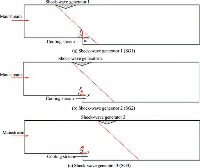
Fig. 3 Models of single cooling-stream injection with a shock wave.
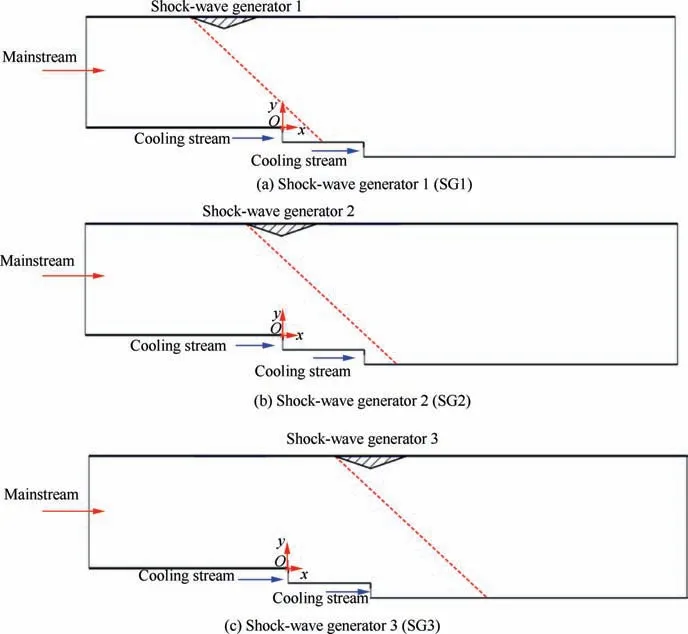
Fig. 4 Models of segmented cooling-stream injection with a shock wave.
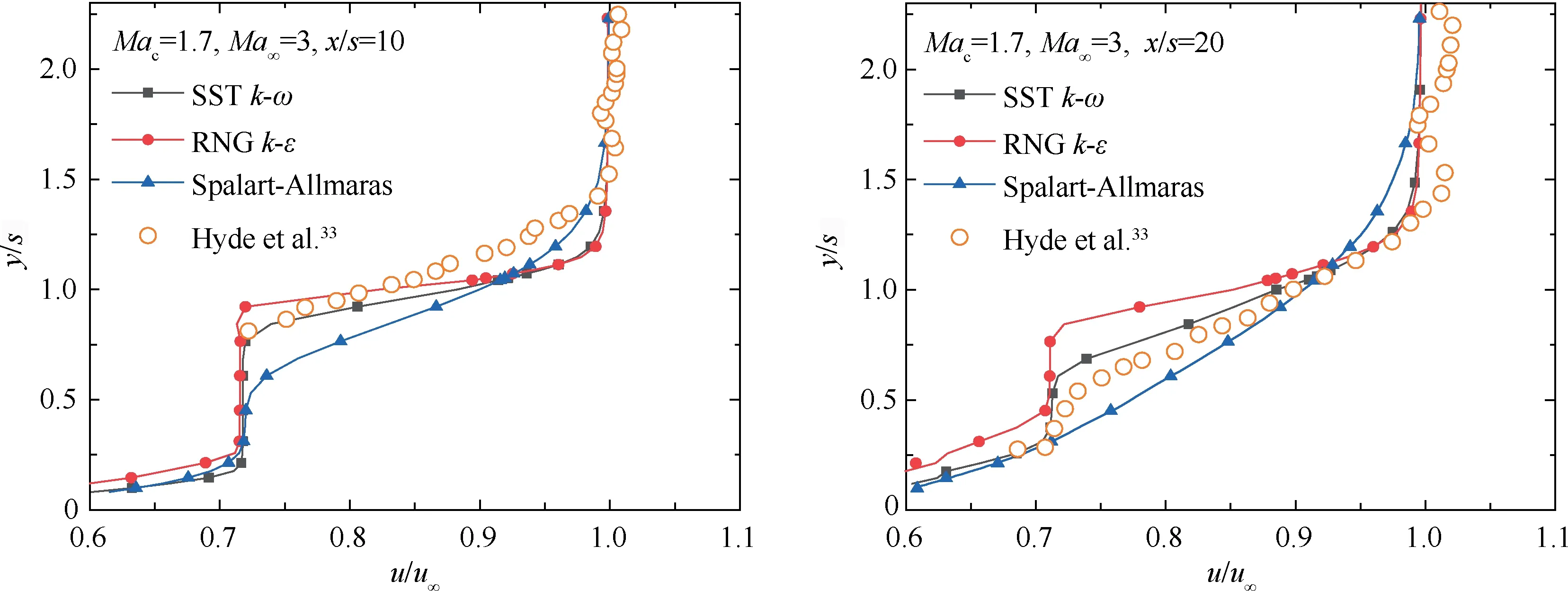
Fig. 5 Comparison of numerical results with data of Hyde et al.
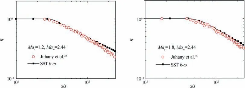
Fig. 6 Comparison of numerical results with data of Juhany et al.
Since shock waves affect supersonic film cooling negatively,it is of great importance to weaken their influence. Peng and Jiangproposed a slotted wall structure with a cavity and demonstrated its superiority numerically.Olsen et al.showed that increasing the coolant mass flow rate could reduce the heat transfer enhancement of a weak shock wave, but would not significantly improve the cooling effect when a strongshock wave was considered. Peng et al.found that when strong shock-wave impingement was considered, reducing the height of the coolant inlet and increasing the coolant Mach number while maintaining the same coolant mass flow rate could be conducive to supersonic film cooling.

Table 1 Governing equations.
Existing studies on restraining the negative effects of shock waves are limited. Further studies are needed to find approaches to weakening interactions between shock waves and cooling films and improving supersonic film cooling effectiveness. This is significant to supersonic film cooling applications.In previous studies,the cooling stream was injected from a single inlet.The present study proposes a segmented coolingstream injection structure and numerically analyzes its effect on supersonic film cooling when the coolant mass flow rate is kept constant.
2. Model
2.1. Physical model
Models of single and segmented cooling-stream injection without shock waves are shown in Fig.1.The cooling stream enters the flow field parallel to the mainstream. The calculation area is 1.5 m long and the upstream length of the first coolant inlet is 0.5 m.The mainstream inlet is 0.15 m high.In single coolingstream injection, the coolant inlet is 5 mm high. In segmented cooling-stream injection, the second coolant inlet is 0.1 mdownstream of the first coolant inlet and the two coolant inlets are both 2.5 mm high so that the coolant mass flow rate is thesame as that used in single injection.All the separating lips are 1 mm thick.Thus,in Fig.1,s=5 mm,s=s=2.5 mm,and t = t= t= 1 mm.

Table 2 Calculation conditions.
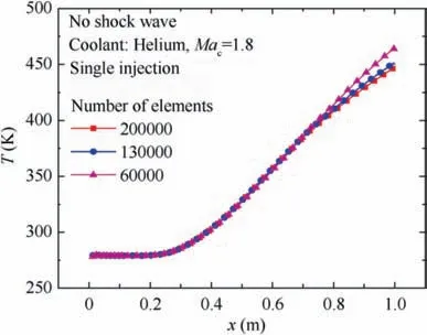
Fig. 7 Mesh independence study.
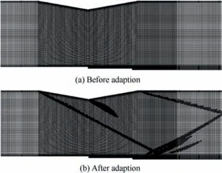
Fig. 8 Meshes before and after adaption.

Table 3 Blowing ratios for four cases investigated in present study.
A wedge-shaped shock-wave generator is used to investigate the effect of shock-wave impingement, as shown in Fig.2.The shock-wave generator is 0.227 m long and its turning angle is either 7°or 10°. The present study considers three shock-wave generator positions. Shock-wave generator 1 is located at x = -0.12 m for the 10° shock wave and x = -0.17 m for the 7° shock wave, whose impinging region is between the two coolant inlets. Shock-wave generators 2 and 3 are located at x=0 m and x=0.10 m,respectively,regardless of whether the turning angle is 10°or 7°.Thus,the impinging region is behind the second coolant inlet. The impinging region of shock-wave generator 3 is further downstream. The shock-wave generator positions are the same for single cooling-stream injection as for segmented cooling-stream injection.
Models of single and segmented cooling-stream injection with a shock wave are shown in Figs. 3 and 4, respectively.SG1, SG2, and SG3 refer to the three shock-wave generator positions.
2.2. Model validation
To choose an appropriate turbulence model for numerical simulations,three turbulence models including the SST k-ω,RNG k-ε,and Spalart-Allmaras turbulence models were used to calculate the simple supersonic film cooling model by Hyde et al.In Fig. 5, u represents the fluid velocity at which the mainstream and the cooling stream mix, urepresents the mainstream velocity, and s represents the height of the coolant inlet. Maand Marepresents the Mach number of cooling stream and mainstream, respectively. The results indicate that the SST k-ω turbulence model gives the best numerical prediction of the three models.Moreover,Peng et al.used SST k-ω turbulence model to calculate supersonic film cooling along a plate and compared the calculational results with the experimental data of Juhany et al.Their results shown in Fig. 6(η is the supersonic film cooling effectiveness)also indicate that SST k-ω model is suitable for the prediction of supersonic film cooling.
2.3. Governing equations and numerical simulation methods
The governing equations are shown in Table 1 and the meaning of the variables can be seen in ANSYS Inc.

Fig. 9 Film cooling effectiveness distributions.
Computational Fluid Dynamics (CFD) method can simulate the characteristics of flow and heat transfer and is promising to play an increasingly important role in aerospace,nuclear energy, powder technology and other fields.The present study uses the commercial CFD software ANSYS-Fluent 15.0 to perform numerical simulations. The second-order upwind algorithm is used to discretize the advection terms in the momentum, energy, mass transport, turbulent kinetic energy and specific dissipation equations. Convergence occurs when the residuals of all variables are less than 10.
The calculation conditions for the mainstream inlet and the coolant inlets are shown in Table 2. For all cases, the mainstream is air and the Mach number is 3.0. The cooling stream is helium or nitrogen and the coolant Mach number is either 1.3 or 1.8.
The pressure inlet and pressure outlet boundary conditions are set for the inlets and the outlet,respectively.The adiabatic and no-slip boundary conditions are used for the other walls.
2.4. Mesh
A mesh independence analysis is carried out and the results in Fig. 7 (T is the temperature) indicate that use of 130000 elements is appropriate for each case.To better capture the shock wave, the mesh is adjusted using the mesh adaption function,with about 140000 elements after adaption.Therefore,the present study uses 140000 elements to perform numerical simulation for each case finally.Moreover,the yis approximately 3 for the elements near the wall. The meshes for segmented cooling-stream injection are shown in Fig. 8 before and after adaption.
2.5. Important parameters
The supersonic film cooling effectiveness and the blowing ratio are defined as:
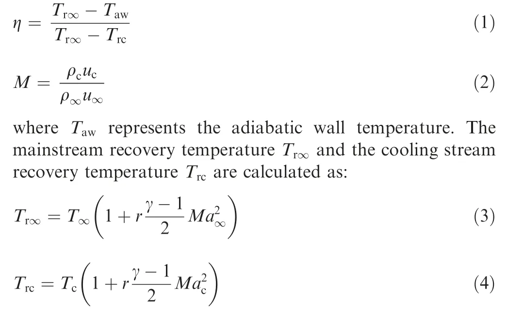
where Tand Trepresents the static temperature of the mainstream and cooling stream,respectively.γ is the adiabatic coefficient, r is the recovery factor, which equals to Prfor the mainstream and the cooling stream.
For Eq. (2), ρuand ρudenote the momenta of the cooling stream and the mainstream. The blowing ratios for the four cases investigated in the present study are listed in Table 3.
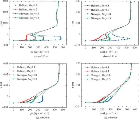
Fig. 10 Momentum distributions along y-direction at x = 0.05, 0.15, 0.30, 0.60 m (single cooling-stream injection).
The cooling-gas mass fraction is defined as:

where mis the mass of cooling stream per unit volume,mis the mass of mainstream per unit volume.
3. Results and discussion
3.1. Film cooling without shock-wave impingement
Film cooling effectiveness distributions without shock waves are shown in Fig. 9. The indicators ‘‘two inlets” and ‘‘one inlet” refer to segmented and single cooling-stream injection,respectively.
With helium as the coolant,the cooling effectiveness of the segmented injection system is higher than that of the single injection system, especially when the coolant Mach number is 1.8.However,with nitrogen as the coolant,the cooling effectiveness of the two systems are quite similar.
Generally, the cooling effectiveness is closely related to the mixing of the mainstream and the cooling stream.The strength of mixing can be analyzed via the momentum distribution of the fluid, the cooling-gas mass fraction near the wall, and the turbulent kinetic energy in the boundary layer.
For single cooling-stream injection, the momentum (ρu)distributions along the y-direction at x = 0.05, 0.15, 0.30,0.60 m are shown in Fig. 10. With the free shear between the mainstream and the cooling stream, the mixing occurs and the two fluids gradually develop into one fluid. The more intense the mixing,the more rapidly the two fluids develop into one fluid. In Fig. 10(b), with helium as the coolant at Ma= 1.3, the mixing is extremely intense and the two fluids have fully developed into one fluid, so the momentum value keeps going up as y increases. While for the other three cases,the two fluids are in the process of developing into one fluid,so the momentum first increases and then decreases with the increase of y.As seen in Figs.10(b)and(c),the mixing degree is weaker at larger coolant Mach numbers regardless of whether the coolant is helium or nitrogen. Moreover, at the same coolant Mach number, the mixing degree when using nitrogen as the coolant is weaker than that when using helium as the coolant.
As for the reason, the blowing ratio M, which represents the difference in momentum between the mainstream and the cooling stream, has an important effect on mixing. Increasing the coolant Mach number can increase the blowing ratio M and reduce the difference in momentum so that the mixing degree decreases. At the same coolant Mach number, the momentum of nitrogen is larger than that of helium, so the blowing ratio M is larger when using nitrogen as the coolant.Therefore, at the same coolant Mach number, the mixing degree is weaker with nitrogen as the coolant than with helium.
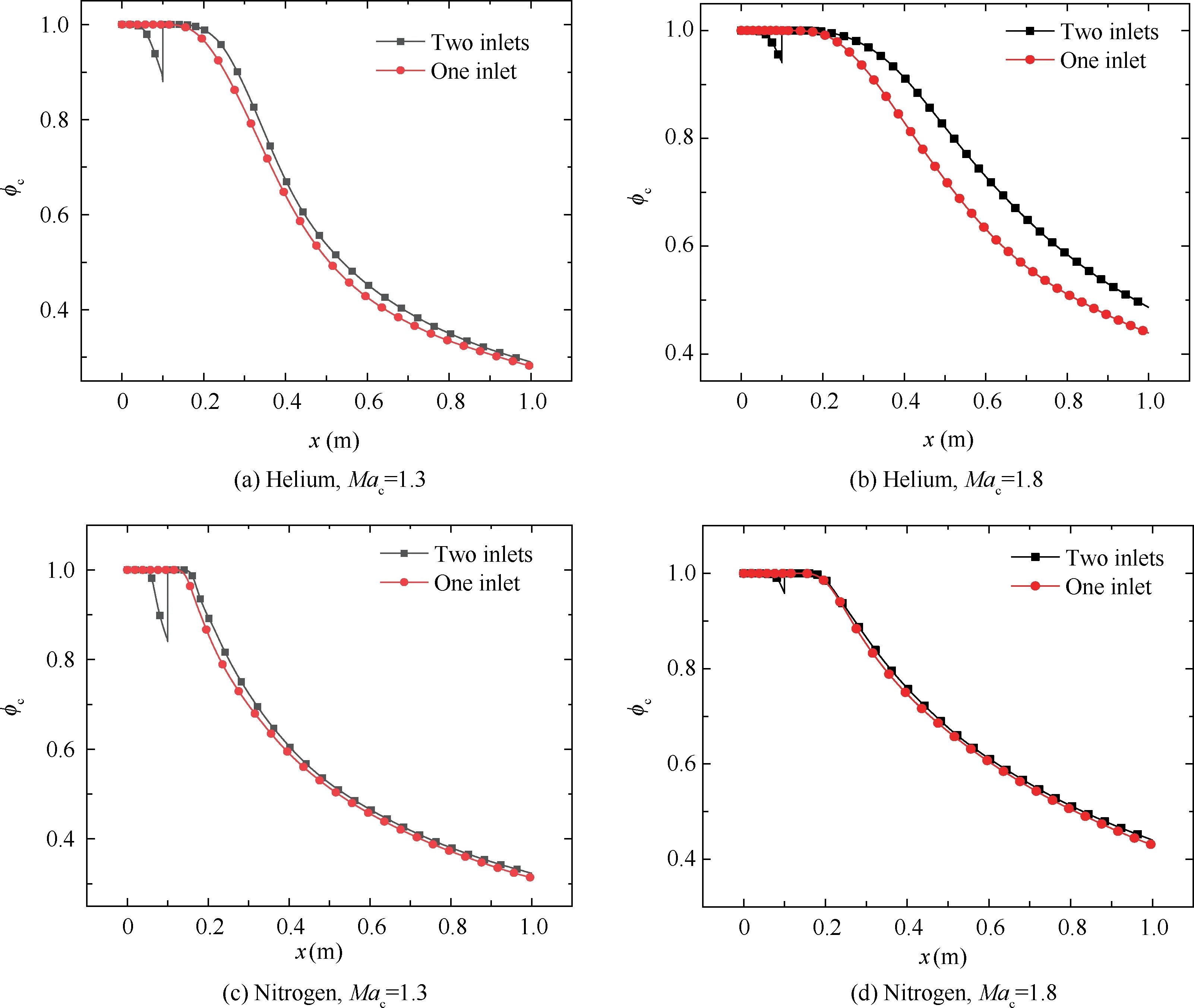
Fig. 11 Cooling-gas mass fraction distributions at 1 mm above the wall.
The distributions of cooling-gas mass fraction and the turbulent kinetic energy(k)at 1 mm above the protected wall are shown in Figs.11 and 12.For segmented cooling-stream injection, part of the cooling stream is injected from the second inlet, and then the two cooling streams merge. Therefore, the turbulent kinetic energy decreases significantly upon the second cooling-stream injection, and then increases. When using helium as the coolant, the turbulent kinetic energy of segmented injection is always lower than that of the single injection. This illustrates that segmented injection reduces mixing degree and thereby improves the cooling-gas mass fraction.When increasing the Mach number of helium,the effect of segmented injection on weakening the mixing is more notable, so the cooling-gas mass fraction improves more obviously.When using nitrogen as the coolant, the mixing of nitrogen with the mainstream is relatively weak, so the advantage of segmented injection to weaken the mixing is not fully reflected.Therefore,the difference in cooling-gas mass fraction is slight with nitrogen as the coolant.
3.2. Film cooling with shock-wave impingement
The film cooling effectiveness distributions with shock-wave impingement and with helium and nitrogen as the coolant are shown in Figs.13 and 14.When the shock-wave impinging region is between the two coolant inlets,for the first section of the protected wall of the segmented injection system,only part of the cooling stream resists the shock wave,so the film cooling effectiveness greatly drops in this region.The other part of the cooling stream enters the flow field from the second inlet and avoids the effect of the shock wave, resulting in a notable improvement of film cooling effectiveness along the second section of the protected wall. This is quite beneficial for the midstream and downstream regions. Therefore, as a whole,segmented cooling-stream injection can achieve better cooling performance than the single cooling-stream injection.
When the shock-wave impinging region is behind the second coolant inlet, the two cooling streams merge before the shock wave and resist the shock wave together, which is close to the cases of single injection. As a result, the advantage of segmented injection is reduced.The difference in cooling effectiveness between segmented and single injection shrinks substantially when the impinging region is closer to the downstream region.
For segmented cooling-stream injection, the momentum distributions along the y-direction at x = 0.01, 0.04, 0.08,0.12 m are shown in Fig. 15. With helium and nitrogen as the coolant, the pressure, mass fraction, and y-velocity distributions are shown in Figs. 16 and 17.
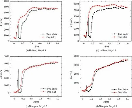
Fig. 12 Turbulent kinetic energy distributions at 1 mm above wall.
In Fig. 15, x = 0.01 m is before the shock-wave impinging region, x = 0.04 m is at the shock-wave impinging region,x = 0.08 m is behind the shock-wave impinging region, and x=0.12 m is behind the second coolant inlet. At x=0.01 m and x = 0.12 m, the difference in momentum leads to mixing of the mainstream and the cooling stream.At x=0.04 m,the momentum of the fluid increases rapidly and the hot and cold fluids clearly develop into one fluid.This indicates that mixing is enhanced greatly as a result of the shock wave.This effect is stronger than the difference in momentum.The local enhanced mixing effect of the shock wave is explained by Figs.16 and 17.The incident shock wave leads to the appearance of a local high-pressure region and a vortex structure in the cooling layer. Therefore, the upward velocity of the cooling stream increases rapidly in the y-direction and a local peak appears at the shock-wave impinging region.This enhances the mixing between the mainstream and the cooling stream.
In Figs. 18 and 19, the cooling-gas mass fraction distributions at 1 mm above the wall are compared for segmented and single-injection systems with shock-wave impingement when helium and nitrogen are the coolants. The turbulent kinetic energy distributions at 0.5 mm above the wall are shown in Fig. 20.
For segmented injection system, when the shock-wave impinging region is between the two coolant inlets, only part of the cooling stream resists the shock wave. Therefore, the local enhanced mixing effect driven by the shock wave leads to the rapid decrease of the cooling-gas mass fraction and the steep increase of the turbulent kinetic energy. However,the other part of the cooling stream enters the flow field from the second coolant inlet behind the impinging region, giving a higher cooling-gas mass fraction near the second section of the protected wall. Then the two cooling streams merge and the turbulent kinetic energy increases in this region. It is worth noting that after the second cooling-stream injection, the turbulent kinetic energy of the segmented injection system is generally lower than that of the single injection system. This indicates that the segmented injection can reduce the mixing degree, so it has obvious advantages in downstream region protection over the single injection.
When the shock-wave impinging region is behind the second coolant inlet, segmented injection causes the two cooling streams to merge and then encounter the shock-wave driven local enhanced mixing effect together. In this situation, the cooling-gas mass fraction improves slightly and the mixing degree is close to that of single injection. This reduces the advantage of segmented injection. When the impinging region is closer to the downstream region, the advantage is smaller.
4. Conclusions
The present study numerically investigates the effect of segmented cooling-stream injection on supersonic film cooling.The results indicate the following:
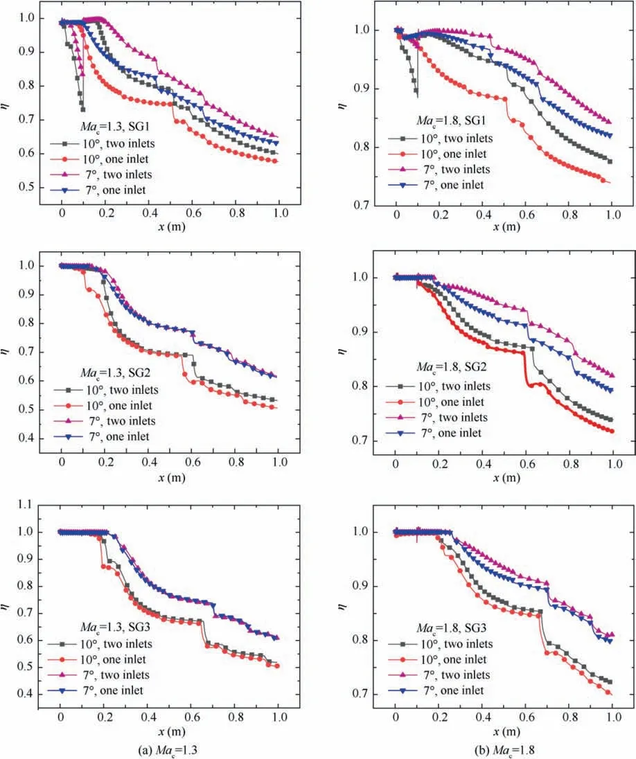
Fig. 13 Film cooling effectiveness distributions with helium as coolant when a shock wave is present.
(1) Without shock-wave impingement, increasing the coolant Mach number can increase the blowing ratio M and reduce the difference in momentum, thus reduce the mixing degree. At the same coolant Mach number,the blowing ratio is larger when using nitrogen as the coolant than using helium, so the mixing degree is weaker with nitrogen as the coolant.
(2) Without shock-wave impingement and with helium as the coolant, the cooling effect of segmented injection is better than that of single injection, especially at larger coolant Mach numbers. However, with nitrogen as the coolant,the cooling effect of segmented injection is quite close to that of single injection.
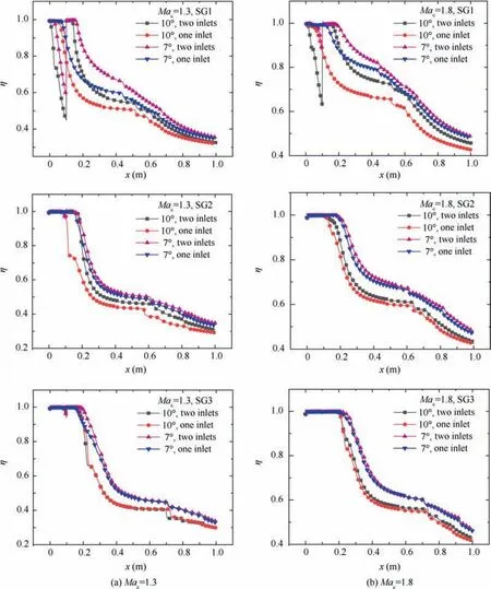
Fig. 14 Film cooling effectiveness distributions with nitrogen as coolant when a shock wave is present.
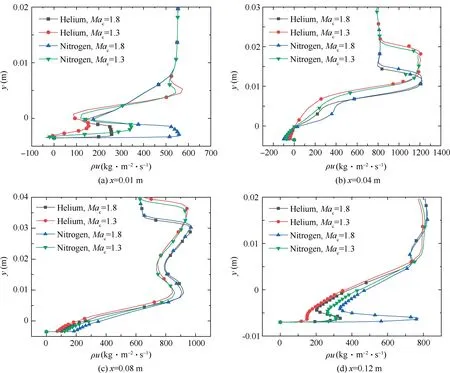
Fig. 15 Momentum distributions along y-direction at x= 0.01, 0.04, 0.08, 0.12 m when a shock wave is present (10° shock wave, two inlets, SG1).
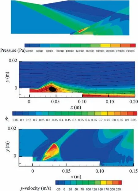
Fig.16 Pressure,mass fraction,and y-velocity distributions with helium as coolant (Mac=1.8, 10° shock wave, SG1).
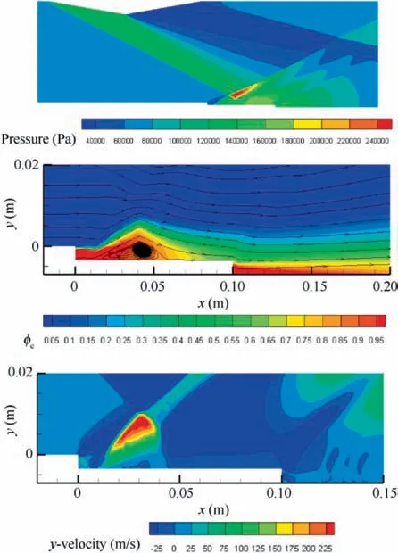
Fig.17 Pressure,mass fraction,and y-velocity distributions with nitrogen as coolant (Mac=1.8, 10° shock wave, SG1).
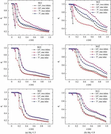
Fig. 18 Cooling-gas mass fraction distributions at 1 mm above wall with helium as coolant when a shock wave is present.
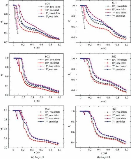
Fig. 19 Cooling-gas mass fraction distributions at 1 mm above wall with nitrogen as coolant when a shock wave is present.
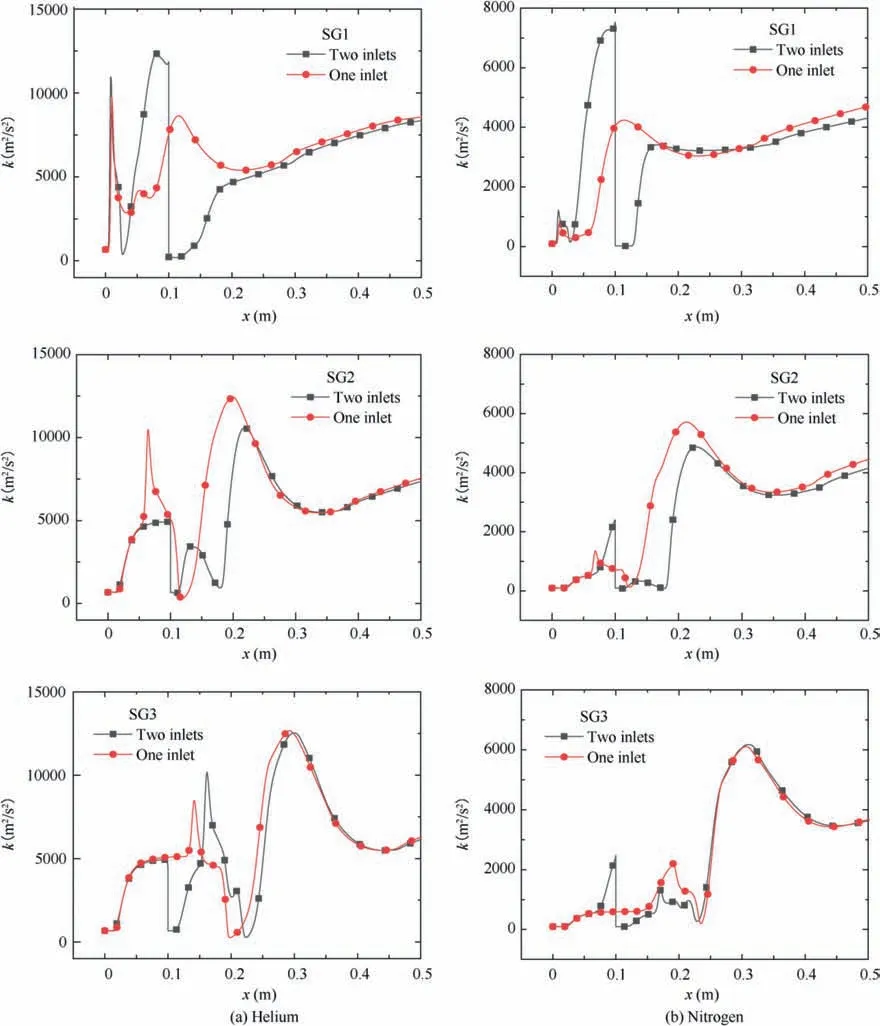
Fig. 20 Turbulent kinetic energy distributions at 0.5 mm above wall when a shock wave is present (Mac=1.3, 10° shock wave).
(3) With shock-wave impingement,local mixing is enhanced greatly due to the shock wave at the shock-wave impinging region regardless of whether the coolant is helium or nitrogen. This effect is stronger than the difference in momentum.
(4) When the shock-wave impinging region is between the two coolant inlets and segmented injection is used, only part of the cooling stream undergoes the local enhanced mixing effect from the shock wave. Thus, segmented injection produces better cooling performance. When the shock-wave impinging region is behind the second coolant inlet, the advantage of segmented injection is reduced. The advantage is much smaller when the shock-wave impinging region is closer to the downstream region. Thus, it is suggested that the additional cooling stream can be introduced after the shock-wave impinging region to weaken the negative effects of shock waves.
The authors declare that they have no known competing financial interests or personal relationships that could have appeared to influence the work reported in this paper.
This study was co-supported by the National Key R&D Program of China (No. 2018YFB1900500) and the National S&T Major Project of China (No. J2019-III-0019-0063).
