Modified attitude factor graph fusion method for unmanned helicopter under atmospheric disturbance
Kecheng SUN, Qinghu ZENG,b,c,*, Jinye LIU,b,c, Wenqi QIU, Jinhen SHI
a Navigation Research Center, Nanjing University of Aeronautics & Astronautics, Nanjing 211106, China
b Key Laboratory of the MIIT Advanced Aircraft Navigation, Control and Health Management, Nanjing 211106, China
c Jiangsu University Collaborative Innovation Center for Satellite Communication and Navigation, Nanjing 211106, China
KEYWORDS Attitude correction;Factor graph;Integrated navigation;Strong airflow environment;Unmanned aerial helicopter
Abstract The Unmanned Aerial Helicopter (UAH) has attracted increasing attention in the military and civil areas with the unique flight performance.The significant impact on the attitude measurement performance of UAHs by the strong airflow disturbance is an essential factor threatening flight safety. To improve the attitude measurement performance of UAHs under atmospheric disturbance,an attitude fusion method over the factor graph is applied and provides the plug-and-play capability.Based on the relationship between position,velocity and attitude,a new attitude correction algorithm for the Modified Attitude Factor Graph Fusion (MAFGF) navigation method is designed and constructed through the fused position and velocity information. Finally, results of simulation and experiment are given to show the effectiveness of the proposed method.
1. Introduction
Due to Vertical Take-Off and Landing (VTOL) and hovering capabilities, the helicopters have been widely used in many unique applications,such as maritime search,forest fire rescue,energy probe, and commercial transportation to inconvenient traffic places. Despite better characteristics than other aerial vehicles, UAHs are profoundly affected by complex atmospheric environment.Due to the attitude fluctuations, UAH is vulnerable to the complicated atmospheric disturbance,which appears at low-altitude.And the high-precision attitude information for the UAH system under atmospheric disturbance is essential to be solved.
Many researchers are devoted to improving the reliability and the quality of the UAH state measurement.Merz et al.studied the autonomous and accurate landing method of UAH based on the Inertial Measurement Unit(IMU)and vision sensors.Hoy et al.researched the navigation method of UAH for the urban environment. Kim et al.proposed the Vision coupled Inertial Navigation System (INS) /Global Position System (GPS) navigation system for UAH. Weiss et al.used the autonomous navigation method of UAH based on monocular vision Simultaneous Localization And Mapping (SLAM)in case of GPS failure.Nakanishi et al.studied the GPS/INS/BAROmetric altimeter (BARO) integrated navigation system of UAH considering the influence of ground effect in 2013.Alarconresearched the relative state estimation for autonomous landing on moving platforms in a GPS-denied scenario in 2015. Al-Sharmana et al.proposed intelligent attitude and flapping angles estimation of the helicopter under nearhover conditions in 2018. Thomas et al.defined the flight state model and stability of helicopter using participation factor. Aided by external sensors, these methods have provided an appropriate navigation system scheme. However, former methods obtain high attitude measurement accuracy based on the additional attitude information in stable flight environments,which results in practical difficulties under atmospheric disturbance.
Considering the random change of the atmospheric disturbance and the unpredictable performance of the installed sensors, the traditional filtering algorithms are hard to satisfy the attitude accuracy requirement of UAH. The factor graph circumvents these deficiencies with its flexible structure and its capability of plug-and-play.The factor graph theory,which originated from the coding theory, has been gradually developed in the navigation area.In 1981,Tannerintroduced a bipartite graph to describe the parity check matrix of lowdensity parity-check codes,called the‘‘Tanner graph”.Kschischang et al.abstracted the factor graph concept and the sumproduct algorithm based on the Tanner graph, the Wiberg graph and other graph models. Loeliger et al.unified the Kalman filter and the least square method with the sumproduct algorithm based on the factor graph in detail, and described the estimation algorithm through the factor graph model. Indelman et al.proposed an inertial/visual information fusion method based on the factor graph, representing the information fusion problem as a factor graph model.Kaess et al.proposed a method to include infinite planes into a least-squares formulation for mapping. Hsiao et al.optimized the poses of the keyframes and landmark planes in a global factor graph using incremental smoothing and mapping. Zeng et al.proposed an improved factor graph multisensor fusion navigation algorithm and realized the UAV integrated navigation system method. These methods have improved the navigation performance while retaining the plug-and-play capability of graph theory. In order to improve navigation accuracy, more navigation sensors are required to provide sufficient measurement values. Especially in terms of attitude, single antenna GNSS is used on UAH, and it provides only position and velocity measurements values. To improve the attitude factor graph’s accuracy, factor graph methods require sensors other than IMU and GNSS.
As we know, the Global Navigation Satellite System(GNSS) provides position and velocity measurement informationand there are not enough factor nodes in the attitude factor graph. Without other attitude measurement sensors,the attitude state of UAH is easy to diverge under atmospheric disturbance. To make full use of the information of the UAH sensors in atmospheric disturbance environment, a modified attitude fusion navigation method based on the factor graph is proposed.This MAFGF navigation method for UAH under atmospheric disturbance is based on the relationship between the error of attitude, position and velocity. In contrast to the traditional factor graph algorithm, the proposed method can improve the accuracy of the attitude factor graph, and then optimize the result of position and velocity fusion. Compared with the traditional Kalman filter method of optimal estimation, our proposed method has the same accuracy and better robustness.The proposed method is less dependent on attitude measurement sensors while the recent studies by other researchers are more focused on integrating more measurement sensors. Even if there is no dedicated attitude measurement sensor, a better attitude accuracy can be obtained only relying on IMU and GNSS by the method in this paper.
The contents of this paper are organized as follows. The system model and information fusion problems are defined in Section 2. The factor graph equations for nodes in factor graph navigation systems are introduced in Section 3. The MAFGF navigation method and its attitude error equations are shown in Section 4. Simulations and experiments are presented in Section 5, and concluding remarks are given in Section 6.
2. Influence of atmospheric disturbance on UAH navigation system
Taking the microburst, which belongs to windshear, as an example, there are strong crosswinds and downward flowsin Fig.1.The helicopter will experience the contrary wind first and go through the tailwind afterward, accompanied by airframe vibration. Therefore, as a kind of wind field impact,the microburst is a massive threat to flight safety, which had caused many accidents. When the helicopters fly at altitudes less than 1000 m, there is a high probability of encountering the microburst, and the influences of a wind field’s aerodynamic force on helicopter rotors are very complicated.
It is an urgent problem to improve the attitude accuracy of UAHs under atmospheric disturbance. What we need to do is obtain more robust navigation information from multi-source heterogeneous sensors.Due to the influence of the atmosphere, some sensors may become inactive for a short time.Our goal is to improve attitude measurement accuracy by fusing all the available information adaptively.
2.1. Scheme of UAH navigation system
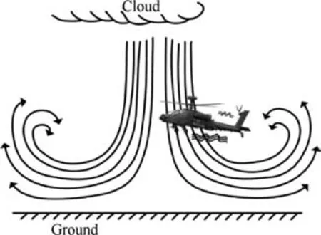
Fig. 1 Diagram of unmanned helicopter under strong airflow disturbance.
In the UAH navigation system,there are many ways to get the state information of UAH, such as IMU, GNSS, Air Data System (ADS), MAGnetometer (MAG), and Electro-Optical navigation System (EOS), etc. UAH is assumed to equip with a set of multi-rate sensors, and some sensors do not work all the time. For example, ADS is greatly disturbed by the atmosphere. The measurement range of EOS is related to the distance from the camera to the target.The magnetometer can only provide a heading angle and is sensitive to the environment. Due to the unstable attitude angle under strong airflow disturbance, there is an urgent demand for attitude measurement accuracy. The MAFGF navigation method is proposed in the paper using sensors to ensure the accuracy of attitude. The scheme of the navigation system based on the MAFGF is shown in Fig. 2.
As the different kinds of factor nodes in the factor graph,the multi-sensors can provide position, velocity, attitude measurements. And the position, velocity and attitude measurements of each sensor are fused into position factor graph filter,velocity factor graph filter and attitude factor graph filter respectively. Unlike the traditional factor graph method in which three factor-graph filters are independent of each other,the attitude factor graph in MAFGF is modified by the fused information of position factor graph filter and velocity factor graph filter, which improved the accuracy of attitude information.
2.2. Navigation system response under atmospheric disturbance
Considering the navigation system scheme mentioned above,the linear superposition method simulates the general form of helicopter stateunder the atmospheric disturbance. There are two kinds of atmospheric disturbance, windshear and turbulence, which significantly affect UAH flight security. The atmospheric disturbance mathematical model is described as a continuous random fluctuation superimposed on the UAH states. The velocity modes of windshear and turbulence can be found in Figs. 3(a) and (b). They are all with the changing wind vector along with a certain distance in the vertical or horizontal direction.
It is a simplified method to superimpose wind field variables on helicopter state variables, but it is very hard to be eliminated in reality. The rotor aerodynamic of UAH is often changed by the wind influence, which further leads to the variety of the temperature and magnetic field of avionics and control system. In this way, the atmospheric disturbance will also affect the accuracy of navigation state and navigation system, and even lead to the failureof navigation sensors.
The influence of the vibration environment disturbed by the atmospheric disturbance on navigation sensors is sometimes fatal. The atmospheric disturbance may cause the instability of IMU or damage of electronic components.When the angular velocity vector is integrated, the errors caused by vibration will accumulate continuously, which will have a significant impact on attitude and position measurements. Besides, kinds of gyroscopes,such as Fiber-Optic Gyroscope(FOG),applied widely in UAH,are also sensitive to the temperature and magnetic field caused by the complex airflow environment.
Except for the IMU, strong airflow disturbance also influences GNSS. The vibration of airborne satellite receivers will cause the phase noise of the reference clock.The measurement errors of Phase Locked Loop(PLL)will be increased,and the system’s tracking performance will be affected.
The atmospheric disturbance may also affect other sensors on the helicopter.ADS is sensitive to atmospheric disturbance,and the barometric height fluctuates wildly under strong airflow disturbance.
Therefore, during the helicopter flight under atmospheric disturbance, the performance of sensors will be affected dramatically. The hardware & software faults may occur randomly, and the attitude information of UAH is far from enough.
3. Factor graph equations
Centralized filtering or federated filtering are used for information fusion. When parts of the sensors go wrong, the system and primary filter must be reconstructed, which will affect the accuracy and timeliness of the navigation system. Therefore, the navigation systems’ flexible filtering structure has excellent research prospects,which will help realize fault isolation and plug-and-play in the navigation system of UAH under atmospheric disturbance.
The bipartite graph’s characteristic is that the graph’s vertex can be divided into two disjoint sets, and each edge can connect two kinds of nodes. The Factor graph is a bipartite graph model which is used to represent factorization.The main purpose of the modeling based on factor graph is to simplify the complex systems by factorization.According to the specific situation,modeling based on factor graph can solve the breakdown problem.

Fig. 2 Scheme of navigation system based on the MAFGF algorithm.
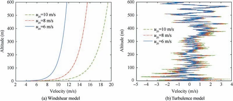
Fig. 3 Atmospheric disturbance velocity models.
3.1. Factor graph method
Factor graph is composed of nodes and edges.A unique factor node can represent each local function in the system, and an individual variable node represents each variable. When a function is related to a variable,the corresponding factor node and variable node are connected by the edge. The edge between the variable node and the factor node means the information interaction. In the factor graph framework, the state estimation is studied by the maximum posterior probability estimation algorithm.
In the factor graph model G=(F,X,E), there are two types of nodes: fis the factor node and f∈F, which represents the local function in the factorization; xis the variable node and x∈X,which means the variable in the global function. eis a connecting edge between nodes and e∈E.
Before discussing the fusion process, we present factor equations for some standard sensors in modern navigation systems. According to the actual characteristics of the IMU in UAH, an integrated navigation framework based on factor graph is constructed in Fig.4.The reference sources in the system are the IMU, GNSS, EOS and ADS. The measurement equations of the four navigation systems are transformed into four kinds of factor nodes. In Fig. 4, the hollow circles represent the state variable node, and the solid circles represent the factor node. Xrepresents the navigation state of the system,and f(·) represents the measurement information of each sensor: frepresents the measurement information from the IMU, which is related to the navigation state of time tand t. f, fand frepresent the measurement information from GNSS, EOS and ADS, respectively. Considering the Magnetometer and IMU usually form Attitude and Heading Reference System (AHRS) together, we do not treat the magnetometer as a separate factor node in the factor graph.The adding factor time is related to the system’s working process and the update frequency of the measurement information.
The integrated navigation system based on factor graph architecture can effectively implement the plug-and-play capability. If one sub-navigation system breaks down due to the atmospheric disturbance, the corresponding factor can be peeled off from the system in real-time. After the fault is eliminated, this navigation subsystem factor can be re-added to the integrated navigation filter. The multi-sensor information fusion method based on factor graph is an effective method to solve the asynchronous problem of multi-sensor observation data. Suppose there is other new sensor measurement information that needs to be added to the navigation system.In that case,we should define a new corresponding factor node,and update the state variable and the corresponding cost function according to the observation equation of the new sensor.
3.2. Variable nodes of the factor graph fusion system
In the scheme designed in Fig. 4, the East-North-Up coordinate is used as a navigation coordinate. There are three kinds of factor graphs which include position, velocity and attitude.The variable nodes of the factor graph are dimensional system state and shown as follows

where the nine variables are the navigation output parameters of the inertial navigation system.Among them,φ,φ,φare platform misalignment angles;δv,δv,δvare velocity errors;δL,δλ,δh are latitude, longitude and height errors.
3.3. Factor nodes of the factor graph fusion system
Several factor equations for different measurement models are presented in this section,covering some sensors in typical navigation applications.The navigation sensors are IMU with the magnetometer, GNSS, ADS and EOS.
3.3.1. Prior factor
The prior factor information f()can be regarded as an individual factor, and is defined as

if the prior factor follows the Gaussian distribution, the prior information is given in terms of the probability density with the mean μand the covariance Σ.

Fig. 4 Schematic diagram of integrated navigation framework based on factor graph.
3.3.2. IMU factor
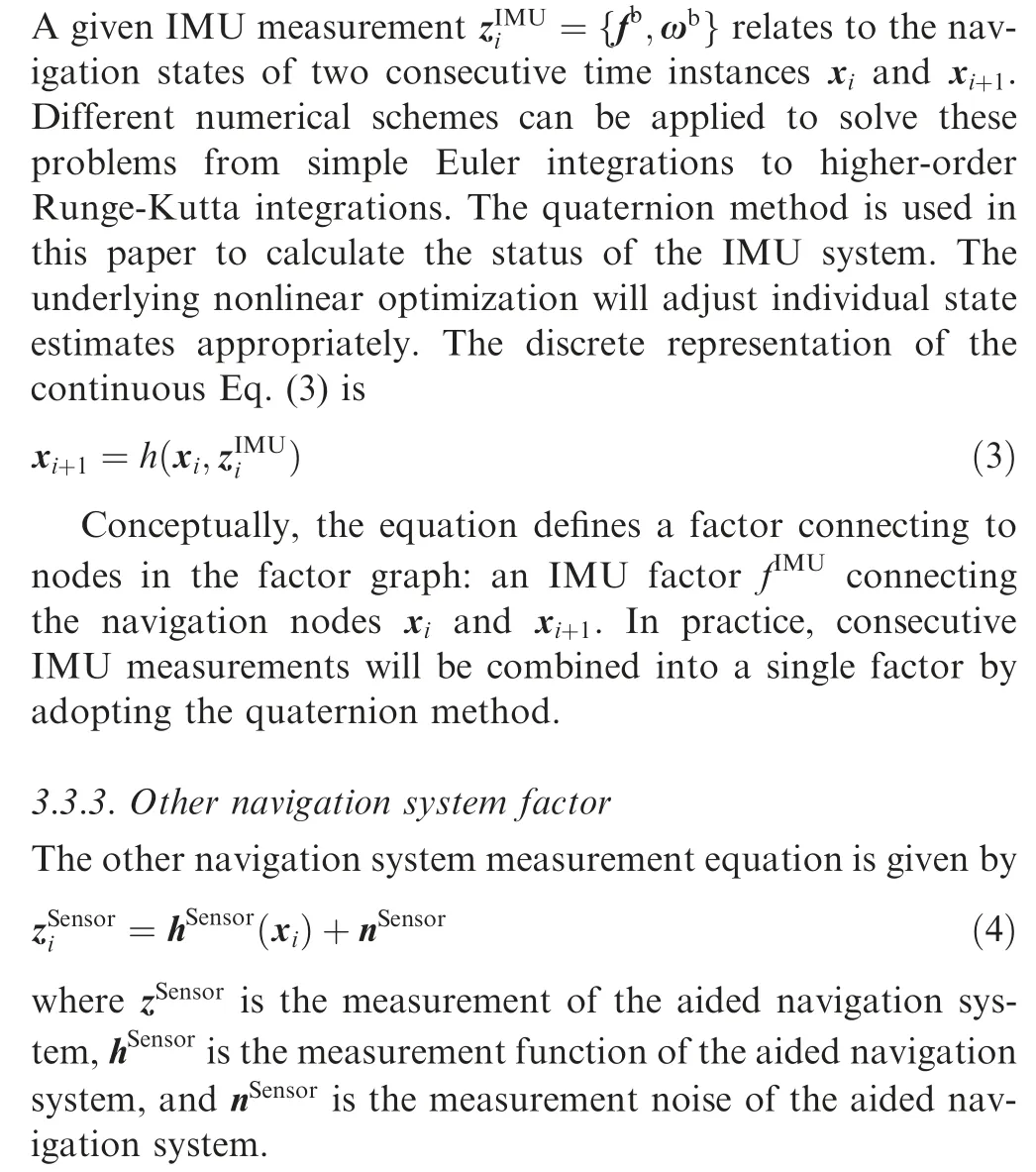
3.4. Multi-source data fusion equations
According to each sub-system’s state equation and measurement equation,we calculate the factor graph fused information by a standard Levenberg-Marquardt optimizer. The fusion method is shown as follows based on the factor graph theory and the mathematical model of integrated navigation.

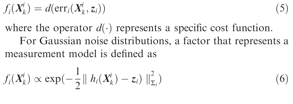
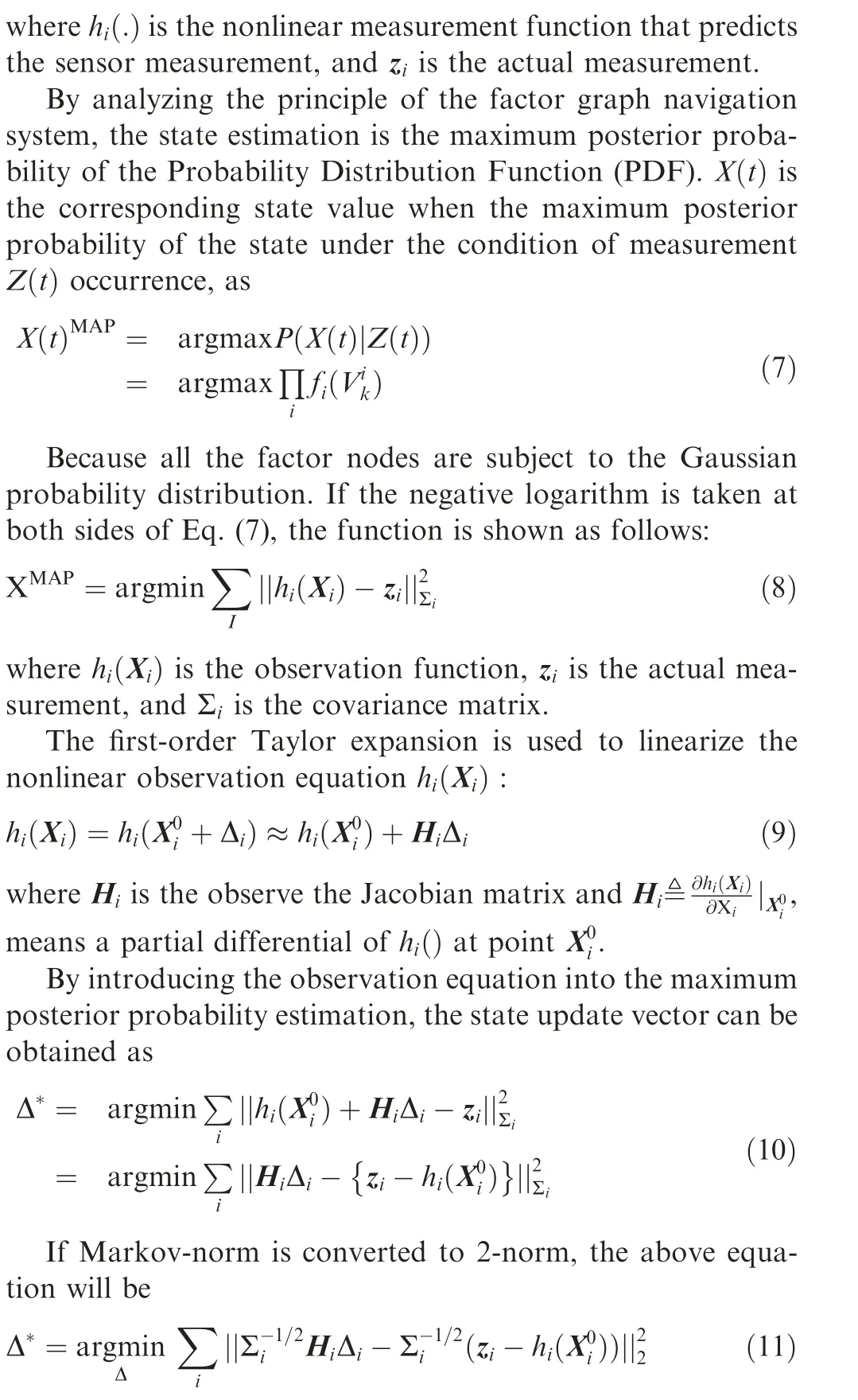
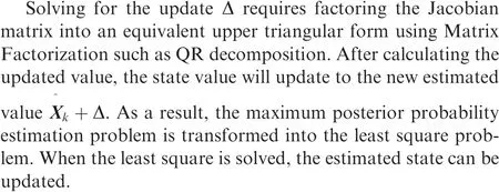
It can be seen from the above content that the factor graph adds the new measured value as a factor node to the middle graph. Unlike the federated filter, which has the main filter,a unified filter needs to be performed at the lowest common frequency moment. The factor graph is optimized every time a factor node is added,so that asynchronous measurement values can be merged.For the same reason,when the sensor fails,the federated filter eliminates the faulty filter. It needs to rebuild the main filter to prevent the faulty sensor from affecting the main filter. The factor graph method only needs not connect the measurement factor of the faulty sensor.
4. New attitude correction algorithm for MAFGF navigation method
The change of attitude angle and altitude is the most prominent influence of atmospheric disturbance on the helicopter.Except for IMU, few sensors provide attitude angle measurement. If there is no other attitude measurement, the atmospheric disturbance will cause the cumulative error of attitude angle in the attitude factor graph.
Considering the GNSS antenna’s installation space is limited on UAH,GNSS provides only position and velocity measurements.The position and velocity factor graph are added to the system by the GNSS measurement factor node. To improve the attitude factor graph’s accuracy, we propose a modified attitude correction method based on the attitude factor graph filter.
The carrier’s attitude error angle satisfies the following equation without considering the small quantity of the second-order attitude error.
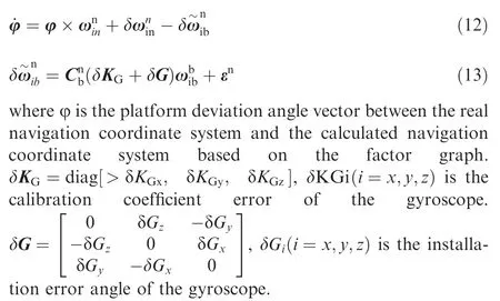

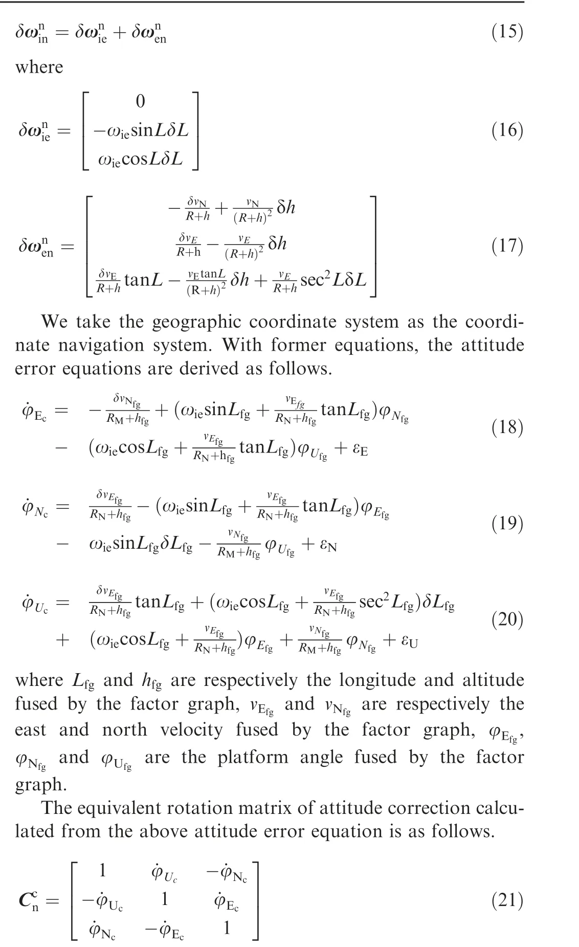
Due to the existence of attitude error,the attitude fused by factor graph is used as the coordinate calculation system,which is close to the real navigation coordinate system with the attitude error. The attitude angle matrix calculated from the attitude factor graph is as follows,

where θ, γand ψare respectively the attitude angles in three directions fused by the factor graph.
Then the modified attitude information is calculated by the following equation.

Substitute Eqs. (21) and (22) into Eq. (23), then the modified attitude angles are shown as follows.

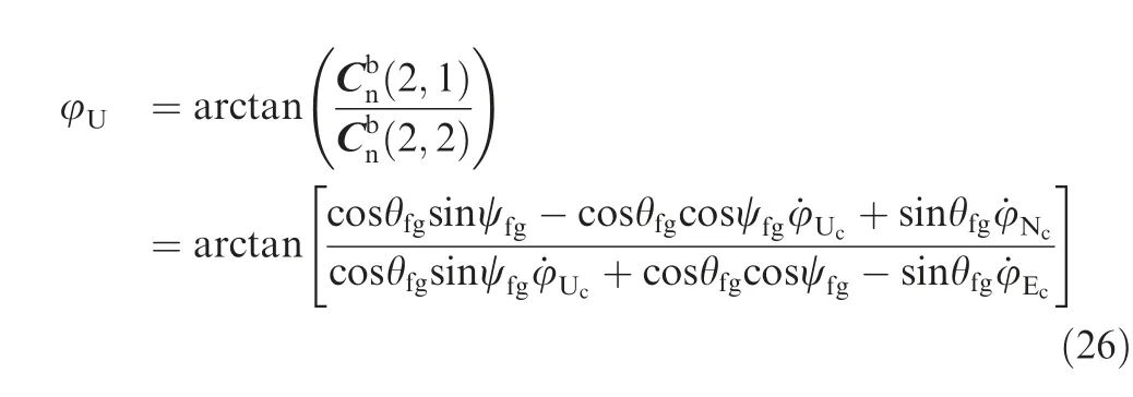
From the above equations, the platform error angle is closely related to the carrier’s position, velocity, and velocity error. The attitude error of IMU is estimated by the above mapping relationship based on the position and velocity information fused by factor graph. The fused position and velocity information is used to modify the attitude factor as shown in Fig. 2, and the more accurate attitude values can be obtained.
5. Simulation and experiment
In order to simulate the navigation information of the UAH under the atmospheric disturbance environment to verify the effectiveness of the MAFGF navigation algorithm, a comprehensive simulation verification platform of the proposed algorithm under strong airflow interference based on factor graph is established in this paper.
A verification platform for UAH navigation in the atmospheric environment based on MATLAB is established. With the atmospheric disturbance environment, flight trajectory,atmospheric disturbance parameters and navigation parameters of UAH under the strong atmospheric disturbance are obtained.Therefore,the MAFGF navigation algorithm is verified in the following section.
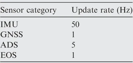
Table 1 Sensor update setting.
5.1. Simulation results
According to the actual flight path requirements of UAH, we design a 800 s flight trajectory. The takeoff point is 114.18°N,22.30°E,100 m.The initial velocity in three directions is 0 m/s,and the initial attitude angle in three directions at the takeoff point is 0°.
Given the update frequencies of different sensors are shown in Table 1.The error parameters of the inertial navigation system are shown in Table 2, the error parameters of aided navigation systems are shown in Table 3.
The atmospheric disturbance is added to the flight path of the helicopter.In the horizontal direction,the superposition of windshear and turbulence is applied in the simulation. In the vertical direction, turbulence is used without windshear. The superposed atmospheric model is shown in Fig. 5. The atmo-tion error given by the proposed method, traditional factor graph and EKF are shown in Fig. 8.
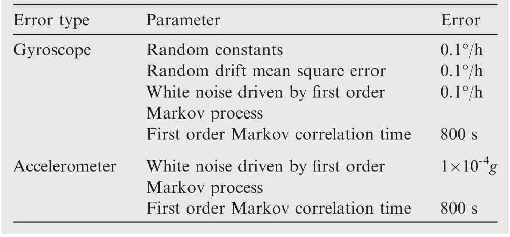
Table 2 Parameters of IMU in simulation.
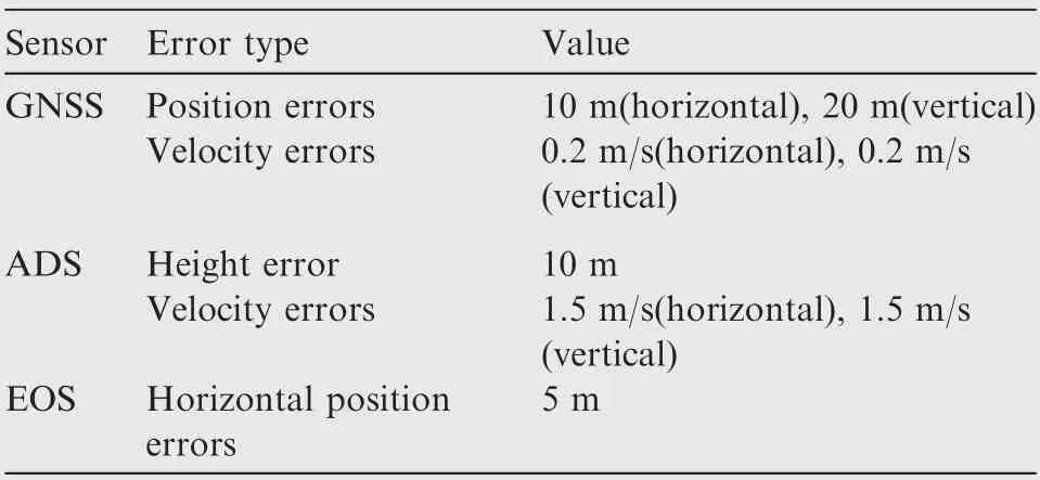
Table 3 Simulation parameters of navigation sensors.
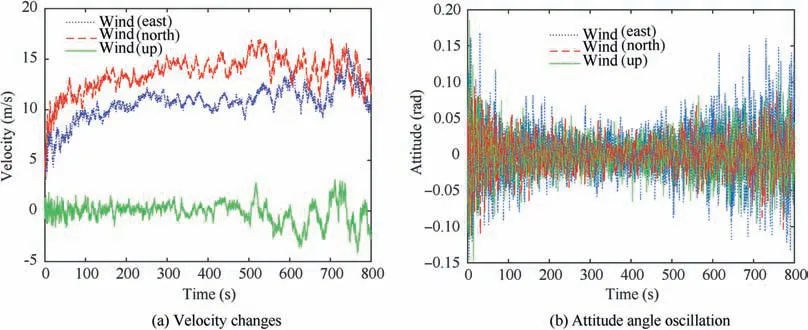
Fig. 5 Simulation diagram of velocity and attitude changes caused by atmospheric turbulence.
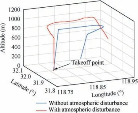
Fig. 6 Affected flight path under airflow disturbance.
From the estimation error RMS values in Fig.8,we can see that the three-dimensional attitude estimation error results obtained by the proposed MAFGF method are much smaller than those given by the traditional factor graph method. It indicates the effectiveness of the proposed method in attitude correction based on the factor graph. At the same time, the horizontal position and horizontal velocity are also well corrected. Compared with the traditional factor graph method,the accuracy of horizontal position is improved by 36.7%.The accuracy of velocity is increased by 36.01%.The accuracy of attitude is improved by 40.52%. The attitude accuracy has mainly been enhanced.
5.2. Experiment results
spheric disturbance is added to the flight path of the helicopter.Turbulence can cause oscillations in the attitude of the unmanned helicopter. The vibration of the helicopter will be synchronously transmitted to the airborne IMU. Simulate wind field impact data through Simulink’s wind module.Under the atmospheric disturbance, the affected flight path is shown in Fig. 6.
Considering the traditional factor graph fusion method without the attitude correction,which is often used in the navigation system with multi-sensors, the comparison of the proposed MAFGF navigation method, the traditional factor graph fusion method, EKF and is shown in Fig. 7.
Under the atmospheric disturbance,the comparison of navigation errors obtained by the proposed method, the traditional factor graph method and EKF is shown in Fig. 7. We can find that under turbulence, the attitude of the helicopter is prone to oscillating changes. Compared with the factor graph method without attitude correction shown in blue, the method proposed in this paper can effectively suppress the divergence of attitude and improve the measurement accuracy of position and speed.The EKF method indicated in green has an accurate model in the simulation, so it also has a better effect on attitude correction. However, comparing the factor graph method that can realize fault reconnection, the EKF method lacks robustness to position and velocity measurement under atmospheric disturbance.In order to show the effectiveness of the MAFGF algorithm,the RMS values of the naviga-Considering there is no actual UAH data for us to test the proposed MAFGF method, we use the laboratory’s sixdegree-of-freedom platform to simulate the vibration under the wind field’s influence and manipulate the MTI sensor to test the proposed algorithm’s effectiveness. In order to simulate the movement of the unmanned helicopter under the wind field more realistically, we manipulated the sixdegree-of-freedom platform to make a circular motion with a radius of 30 mm in the horizontal direction and a sine motion with a height of 10 mm in the vertical direction,and perform the 0.1 radians 10 Hz vibration in the pitch and roll angles.
Based on the relevant analysis of the wind modelin Section 2.2, the use of a six-degree-of-freedom platform can simulate the unmanned helicopter’s angular vibration and linear motion caused by the atmospheric disturbance. The MTI-G-710 GNSS/INS is used to verify the proposed algorithm’s effectiveness. The specifications of the sensors of MTI-G-710 we used are shown in Table 4.
The semi-physical simulation experiment environment is shown in Fig. 9. Since the inertial navigation system is the most significant in the vibration environment of the wind field,in order to test the influence of the navigation status of the helicopter when hovering, we collect the inertial navigation and magnetic data of the navigation based on the MTI sensor installed on the platform. We use GNSS transponders in the laboratory to receive satellite signals for data fusion.The navigation error of each method under the six-degree-of-freedom platform is shown in Fig. 10.
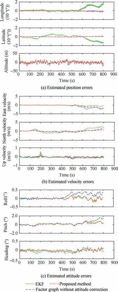
Fig. 7 Fusion states errors obtained by simulation under the turbulence disturbance.
When the six-degree-of-freedom platform vibrates in the roll and pitch direction, the method proposed in this article is compared with the traditional factor graph method and EKF. From Fig. 10, we can see that compared to the traditional factor graph algorithm represented by the blue dash,our optimization in attitude correction has further improved the accuracy of position and speed. Compared with EKF, it has the same accuracy in attitude, but the improvement in position is obvious.
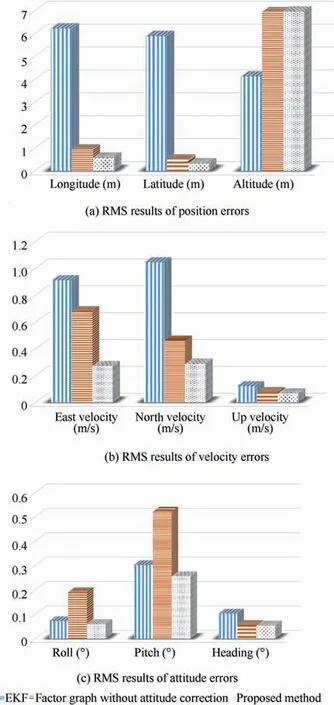
Fig.8 RMS results of state errors obtained by simulation under the turbulence disturbance.
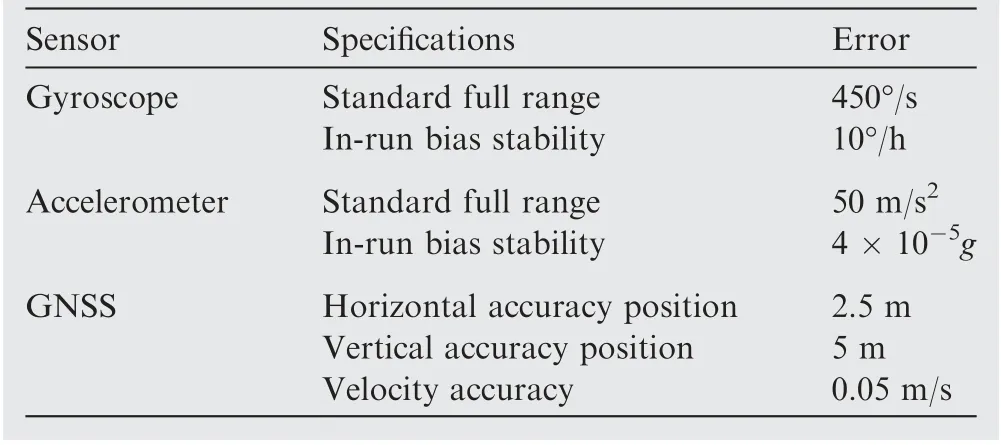
Table 4 Specifications of sensors of MTI-G-710
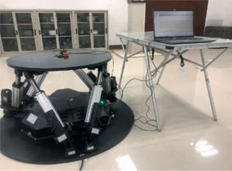
Fig. 9 Six-degree-of-freedom experiment platform.
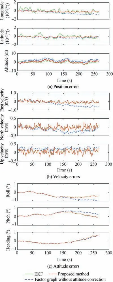
Fig.10 Navigation errors obtained on the six-degree-of-freedom platform.
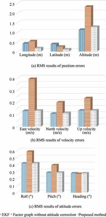
Fig. 11 The RMS results of state errors obtained on the sixdegree-of-freedom platform.
The RMS value of the attitude errors is calculated in Fig. 11. Compared with the traditional factor graph method,for the pitch and roll angles affected by the vibration of the six-degree-of-freedom platform, the accuracy increased by 27.53% on average. Similarly, the attitude correction by the MAFGF method also improves the accuracy of position and velocity. Compared with EKF, the accuracy of attitude and speed are similar,but the position under strong airflow disturbance is improved. Through the experiment of the navigation system under the vibration six-degree-of-freedom platform,the attitude correction effect based on the proposed MAFGF method can also be found.
We make full use of the open data, the IMU-Reference UrbanNav Data provided by the Hong Kong Polytechnic University.These datasets are captured by the vehicle platform during travels around the city of Hong Kong,China.The vehicle platform consists of a navigation system with IMU/GNSS.
The strapdown inertial navigation system provides gyroscopes and accelerometers data to calculate the ground position, velocity and orientation information. The GNSS data includes longitude, latitude, altitude and velocity data. The IMU measurements are provided with the frequency at 100 Hz, and raw GNSS measurements are available with the frequency at 1 Hz. Because of the high-rise buildings in Hong Kong,the GNSS signal is easily reflected or blocked,resulting in multipath effect or breakdown. Similar to the atmospheric environment, sensor performance is unstable and prone to failure.
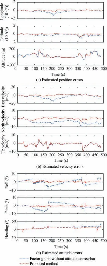
Fig. 12 Navigation errors obtained by the IMU-Reference UrbanNav Data.
As the graph estimation theory, the IMU measurements accumulated by the quaternion algorithm are regarded as an equivalent IMU factor.When GNSS is breakdown due to signal blocking,the data fusion system simply refrains from adding the GNSS factors. GNSS only provides position and velocity measurements. GNSS factor nodes are added to the position and velocity factor graphs. Since the position and velocity variables are fused,the attitude angle can also be corrected based on the coupling relationship between attitude,position and velocity in the state equation and measurement equation. The comparison result can be found in Fig. 12.
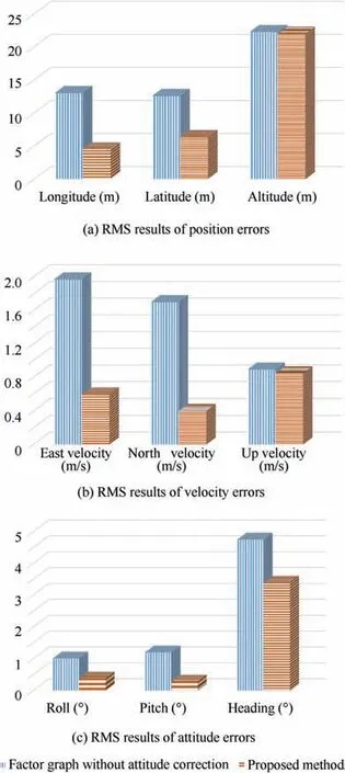
Fig. 13 RMS results of state errors obtained by the IMU-Reference UrbanNav Data.
Fig. 12 shows the navigation error trajectories of the proposed MAFGF method are better than that of the factor graph fusion method without the attitude correction. It can be seen that in the case of no attitude correction (blue line),the attitude angle error accumulates to be divergent,and there will be a jump phenomenon when the vehicle ran in highdynamic movement. The attitude angle error converged with the proposed MAFGF method can be found with the fewer errors.In the dynamic and affected environment,the proposed algorithm has a better measurement performance.
The RMS value of the attitude errors is calculated in Fig. 13. Compare to the traditional factor graph method, the accuracy of the proposed method is significantly improved.For roll and pitch angles, the accuracy increased by 69.61%on average. For yaw angle, the accuracy is increased by 28.57%. Similarly, the attitude correction by the MAFGF method also improves the accuracy of position and velocity.The accuracy of position is improved by 38.61% on average.The accuracy of velocity is increased by 50.48%.
6. Conclusions
The atmospheric disturbance has a significant influence on the attitude measurement stability of UAH, which affects flight performance and safety.In order to improve the attitude measurement performance of UAH in the complex atmospheric environment, the research of a new MAFGF navigation method is introduced in this paper. Conclusions that emerge from this research can be summarized as follows:
(1) Considering that the strong airflow environment has a great impact on the performance of the inertial sensor and the sub-navigation system of UAH, which leads to the degradation of the navigation performance. In particular, the aircraft’s attitude information is greatly affected by the strong airflow because of the existence of turbulence oscillation.
(2) To solve the problem of insufficient attitude measurement, a MAFGF navigation method is proposed in the paper, which corrects the attitude information by the fused position and velocity information of the navigation system.
(3) The simulation and the experimental results show that the MAFGF method can achieve better performance,especially for the attitude improvement for multisource navigation under atmospheric interference. The proposed MAFGF method has better performance than the traditional factor graph method.
The authors declare that they have no known competing financial interests or personal relationships that could have appeared to influence the work reported in this paper.
This study was co-supported by the National Natural Science Foundation of China (Nos. 61533008, 61603181), the Fundamental Research Funds for the Central Universities of China(No. NS2018021) & the Priority Academic Program Development of Jiangsu Higher Education Institutions, China.
