Optimization of cooling structures in gas turbines:A review
Guohu ZHANG, Rui ZHU, Gongnn XIE, Shulei LI, Bengt SUNDE´ N
a School of Mechanical Engineering, Northwestern Polytechnical University, Xi’an 710072, China
b School of Marine Science and Technology, Northwestern Polytechnical University, Xi’an 710072, China
c Department of Energy Sciences, Lund University, SE-22100 Lund, Sweden
KEYWORDS Conjugate heat transfer;Optimization method;Surrogate model;Thermal performance;Turbine cooling
Abstract Attempts for higher output power and thermal efficiency of gas turbines make the inlet temperature of turbine to be far beyond the material melting temperature.Therefore,to protect the airfoil in gas turbine from hot gas and eventually prolong the lifetime of the blade,internal and film cooling structures with better thermal performance and cooling effectiveness are urgently needed.However,the traditional way of proceeding involves numerous simulations,additional experiments,and separate trials. Optimization of turbine cooling structures is an effective way to achieve better structures with higher overall performances while considering the multiple objectives,disciplines or subsystems. In this context, this paper reviews optimization research works on film cooling structures and internal cooling structures in gas turbines by means of various optimization methods.This review covers the following aspects: (A) optimization of film cooling conducted on flat plates and on turbine blades or vanes; (B) optimization of jet impingement cooling structures; (C) optimization of rib shapes, dimple shapes, pin-fin arrays in the cooling channels; (D) optimization of U-bend shaped cooling channels, and internal cooling systems of turbine blades or vanes. The review shows that through a reliable and accurate optimization procedure combined with conjugate heat transfer analysis, higher overall thermal performance can be acquired for single-objective or multi-objectives balanced by other constrained conditions. Future ways forward are pointed out in this review.
1. Introduction
The thermal efficiency is one of the most important indices to evaluate the performance of a gas turbine. By increasing the inlet temperature of a gas turbine, its thermal efficiency can be improved.Nowadays, the inlet temperature of advanced turbine engines has already reached above 2000 K, which is far beyond the melting temperature of the blade material.Therefore, to protect the blade from hot gas and eventually prolong the lifetime of the blade, advanced cooling structures with better cooling performances are urgently needed.Film cooling and internal cooling are the most important cooling techniques, as shown in Fig. 1, that protect the turbine blade or vane from the high temperature hot gas.Improving the film cooling effectiveness and enhancing the heat transfer performance in the internal cooling channel have attracted a lot of attention in the past several decades.
Film cooling effectiveness is influenced by many factors,like hole shapes, spacing and orientations, hole length-todiameter ratio, density ratio, blowing ratio and other mainstream parameters. In the past 30 years, numerous numerical and experimental studies were carried out in this field to figure out better structures with higher cooling effectiveness and clarify the corresponding cooling mechanisms. Some researchers provided overviews about state-of-the-art in advanced film cooling. In 2001, Han and Ekkadconducted a review to reflect the recent progress in turbine blade film cooling. Later,Bunkerintroduced the origins of the shaped hole and summarized the relevant knowledge of shaped holes including flow field, heat transfer and film cooling performance from the existing literatures. The literatures on effects of hole shape,surface curvature and freestream turbulence on film cooling effectiveness were reviewed by Bogard and Thole.Kianpour et al.carried out a review to summarize the recent investigations of film cooling effectiveness and mechanisms of different hole shapes, including cylindrical hole, trenched hole, shaped hole, compound hole, trenched shaped hole, compound shaped hole and compound trenched shaped hole. Ekkad and Hanpresented an overview of the effects of coolant density and advanced hole exit geometries on the film cooling effectiveness. Zhang et al.mentioned two main strategies to enhance the film cooling effectiveness.One was a passive strategy like shallow trenches, upstream ramps, shaped holes and mesh-fed slots,and the other strategy was an active one including the use of a plasma actuator and a pulsation modulating device. They presented an overview of the development of advanced film cooling and concluded that the progress of manufacturing methods is promising in reducing the current limits for film cooling technologies.
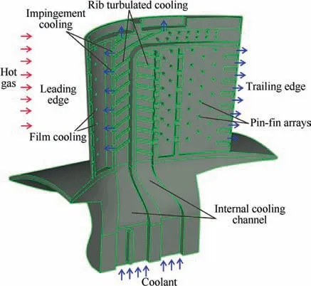
Fig. 1 Schematic of cooling techniques in gas turbines (remade based on figure from www.njtf.cn).
Internal cooling is the earliest used turbine blade cooling method and has been developed with the continuous improved requirements of cooling techniques. Internal cooling is achieved by passing the coolant air through serpentine passage to remove the heat from the inner channel. Several cooling techniques, like jet impingement cooling,rib turbulators,dimples surfaces,other heat transfer augmentation techniquesand pin-fin arrays,are utilized as methods of internal cooling but they are used in different areas of the turbine blade. As shown in Fig. 1, rib turbulators are often mounted in the serpentine passages. Pin-fin cooling is a key technique applied for cooling the trailing edge regions while impingement cooling can be used at the leading edge regions. It should be noted that dimples are commonly used in the tip areas of the blade, although they are not illustrated in Fig. 1. Plenty of works were performed to study the heat transfer enhancement of internal cooling. In 2003, Ligrani et al.reviewed the flow characteristics and mechanisms of several heat transfer augmentation techniques, including pin-fin arrays, dimple surfaces, rib turbulators and swirl chambers. Comparisons of heat transfer performance and thermal performance among these techniques were also presented. Gupta et al.also carried out a review of internal cooling techniques applied in gas turbine blades. Ribbed channels are widely adopted for turbine blade internal cooling.Song et al.presented a review of internal cooling with ribs in both stationary and rotary states.Ligranifurther presented an overview of the development of heat transfer augmentation schemes for turbine blade cooling channel without rotation before 2003,and also for turbine blade cooling channel with and without rotation during the period from 2003 to 2013. Recently, Patil and Borsereviewed investigations of internal cooling channels with various heat transfer augmentation techniques and compared the performance of a single rib pattern with the performance of ribs-dimples/protrusion patterns. In addition, several new developed ribs with good performance were also summarized.
It can be concluded from the reviews that the traditional way of tailoring the film cooling structures and heat transfer enhancement methods involves numerous simulations, many experiments, and separate trials. Through years of development and verification, optimization techniques have been proved to be an effective path for better design while considering multiple objectives of the design. Thus, a great number of research works have been carried out recently focusing on optimization of the film cooling structures and internal cooling structures for achieving higher film cooling effectiveness and better heat transfer performance. Therefore, to draw a clear picture of this research field and give possible research ways forward, this paper reviews the optimization of cooling structures in gas turbines. The main research directions include the optimization studies about film cooling structures and internal cooling structures.
2. Optimizations of film cooling structures
Film cooling is one of most widely used cooling techniques for high-temperature components of gas turbines. In film cooling,the coolant air is ejected through the discrete hole on the surface to form a protective film, which aims to protect the surface from hot gas and extend the lifetime of the components.Fig. 2 shows a schematic view of the film cooling concept.The film cooling performance is largely influenced by the hole shape. Different hole shapes result in different film cooling effectiveness. Therefore, optimization of the hole shape is an effective way to figure out the hole shape with better film cooling performance.
2.1. Film cooling optimizations conducted on flat plates
Lee and Kimperformed optimization of a cylindrical hole by using six surrogate models, i.e., three basic models, Response Surface Approximation (RSA) model, Kriging metamodeling technique(KRG)and Radial Basis Neural Network(RBNN) and three Weighted Average surrogate models(WTA), WTA1, WTA2 and WTA3. The objective function of the optimization problem was the spatially averaged film cooling effectiveness. The length to diameter ratio of the hole and the ejection angle were chosen as the design variables.The Design of Experiments (DOE) was performed by the widely used Latin Hypercube Sampling (LHS) method. Finally, the optimal points based on each constructed surrogate model were searched by the Sequential Quadratic Programming(SQP) algorithm. The results showed that the KRG model,which is the same as the WTA2,predicted the highest spatially averaged film cooling effectiveness compared with other surrogate models and the reference geometry. The same optimization processes and results were adopted and obtained by Kim et al.However,in Kim’s studies,the optimization objective was a cratered cylindrical film hole, and the design variables were three parameters relative to the crater. In addition, Kim et al.also carried out a similar optimization of the shape of a bended film cooling hole. It was found that 39.9%improvement of the spatially averaged cooling effectiveness was achieved by the optimal hole compared with the reference one.
Later, Lee and Kimadopted three-dimensional RANS analysis together with the RBNN methodand the WTA modelto optimize the shape of a fan-shaped hole aiming at enhancing the film cooling effectiveness compared with the reference geometry presented by Saumweber and Schulz.Fig. 3shows the reference fan-shaped hole and the laterally averaged film cooling effectiveness of the referenced geometry and optimized geometry.
During the optimization process, the same objective function, the same DOE method and the same optimal point searching algorithm were selected as in their previous study.In addition, three variables including injection angle, lateral expansion angle and length-to-diameter ratio of the film hole were chosen as the design variables in this work. The results showed that the optimized fan-shaped hole improved the film cooling effectiveness compared with the reference one.
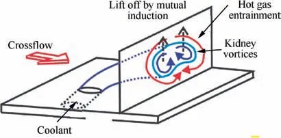
Fig. 2 A schematic view of film cooling concept.20
Recently, Park et al.performed a similar optimization work of a fan-shaped hole but fixed the injection angle and the length-to-diameter ratio of the hole but varied the forward expansion angle, the lateral expansion angle and the metering length ratio. In addition, in contrast to Lee and Kim’s work,the Box- Behnken Design (BBD) method was adopted in Park’s work to select the design point of each parameter and the Pressure-Sensitive Paint (PSP) technique was used to measure the responses at each design point. The BBD method was proposed by Box and Behnken.It is a class of rotatable or nearly rotatable second-order designs based on three-level incomplete factorial designs. Based on Park’s study,Zamiri et al.carried out the a similar optimization work but adopted the Large Eddy Simulation(LES)to capture the detailed flow behaviors of the film cooling process and to accurately predict the film cooling effectiveness of the hole geometries at the design points. The results showed that compared to experimental data, the simulation results of the LES approach were very accurate.Besides,the optimal cooling hole obtained by using the LES method coupled with the BBD approach and RSA provided 49.55% improvement of the cooling effectiveness compared with the reference hole.
The BBD approach together with the RSA method was also employed by Choi et al.to optimize the Coanda bump downstream the exit of a rectangular film hole to enhance the film cooling effectiveness. The width, height, and streamwise position of the peak point of the Coanda bump were selected as the design variables. Fig. 4presents a schematic of the slot and Coanda bump and the dimensionless temperature distribution of the section perpendicular to the surface at X/D = 10 for the referenced and optimized geometry.
They found that the width of the bump had a bigger influence on the cooling effectiveness than other parameters, and the optimal structure improved the cooling performance by about 1.3%, 2.4% and 7.6% at different blowing ratios compared with the reference geometry without a bump. The Coanda effect, also known as a wall-attachment effect, is a phenomenon due to the viscous effect.The moving fluid tends to attach itself toward the near solid wall and flow along it.Benabedcarried out a computational optimization to enhance the film cooling effectiveness and reduce the pressure loss by utilizing the advantages of the Coanda effect. A CFD method with DOE was adopted to optimize the Coanda bump by varying six parameters.
Subsequently,Lee and Kim shifted their focuses to the laidback fan-shaped hole. They separately used Reynolds-Averaged Navier-Stokes (RANS) analysis coupled with four surrogate modelsand the KRG techniqueto optimize the shape of a laidback fan-shaped hole to improve the film cooling effectiveness. In these studies, the influences of four geometric variables, i.e., the injection angle, the forward expansion angle and the length-to-diameter ratio of the hole and the lateral expansion angle of the diffuser, on the film cooling performance were investigated. They all were selected as the design variables during the optimization process.Fig. 5depicts the computational domain, the reference laidback fan-shaped hole and the film cooling contours of the referenced and optimized hole.

Fig. 3 Schematic diagram of reference fan-shaped hole and laterally averaged film cooling effectiveness of referenced and optimized geometry.25
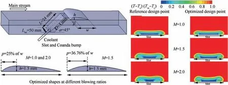
Fig.4 Schematic of slot and Coanda bump,optimized shapes at different blowing ratios and dimensionless temperature distribution of section perpendicular to surface at X/D = 10.30
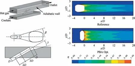
Fig. 5 Schematic diagram of computational domain, reference laidback fan-shaped hole and film cooling contours of referenced and optimized geometry.32
The results of these studies showed that the use of multiple surrogates can improve the robustness of the optimization process with the lowest computational demand, while the use of the KRG technique can provide accurate prediction of the optimum objective function. In addition, it is found that the film cooling performances of optimized geometries at two different blowing ratios of 0.5 and 2.5 are, respectively,31.8% and 44.9% higher than for the reference geometry presented by Saumweber et al.Seo et al.also performed an optimization of the laidback fan-shaped hole but they considered the injection angle, forward expansion angle and the metering length as the design variables. In this study, both RSA and KRG methods were utilized to construct the surrogate models and helped to find the optimal holes. Results showed that the overall averaged film cooling effectiveness was improved of 4.5% and 7.5% by RSA method and KRG method, respectively.
Wang et al.carried out a similar optimization study as they of Lee and Kimdid. The differences between these two studies are the working conditions, the turbulence models adopted in the numerical simulation and the searching methods of optimal points. Wang used the RNG k-ε turbulence model for the simulation for the two blowing ratios of 0.5 and 1.5 while Lee used the SST k-ω for the low blowing ratio of 0.5.A Genetic Algorithm(GA)was applied in Ref.36 while the gradient-based SQP method was applied in Ref. 24. The same reference geometry presented by Ref. 26 was applied in these two works.It was indicated from the results that the optimal geometries significantly increased the film cooling effectiveness. Later, Wang et al.performed an optimization work on laidback fan-shaped hole by using a novel surrogate model called Least Square Support Vector Machine (LSSVM) and it is a kind of chaotic optimization algorithm. It was found that the LS-SVM provided an accurate prediction for the film cooling system and reduced the computational time simultaneously.
Zhang et al.also conducted optimization work on laidback fan-shaped holes.Fig.6compares the film cooling contours, laterally averaged cooling effectiveness and streamlines and x-vorticity distributions between the reference and optimized laidback fan-shaped hole.
It was demonstrated that the optimal geometry improved the film cooling effectiveness by 39%compared with the reference case. In contrast to the traditional fan-shaped hole and laidback fan-shaped hole, a novel shaped hole shown in Fig. 7 was presented by Lee et al.The film cooling effectiveness of the novel shaped hole was numerically investigated and compared with that of the traditional shaped holes at different blowing ratios. The results showed that the novel shaped hole could improve the film cooling performance to a large extent compared with other shaped holes. To further enhance the cooling performance, the optimization work of novel shaped hole was carried out in a later part of this reference. The optimization methods and processes adopted in this work were the same as those in Ref.24.The final optimum design showed an 18.1% improvement of the spatially averaged film cooling effectiveness compared with the reference geometry.
Lee et al. also applied the multi-objective Evolutionary Algorithm (EA) to optimize the shape of a laidback fanshaped holeand a row of laidback fan shaped holes.In these studies, the objectives were to maximize the film cooling effectiveness and reduce the aerodynamic loss. The LHS method was utilized to select the design space. In addition, the RSA method was used to construct the surrogate model of both the objective functions. A hybrid multiobjective evolutionary algorithm NSGA-II combined with a local search method was applied to find the Pareto optimal solutions of the optimization problem. However, in Ref. 41,the four design variables were selected as the injection angle,the forward expansion angle of the hole, the lateral expansion angle of the diffuser and the length to diameter ratio of the hole. On the other hand, in Refs. 42,43, as they focused on a row of film holes, the design variables were, respectively,the injection angle, the forward expansion angle of the hole,the lateral expansion angle of the diffuser and the pitch to hole diameter ratio. It was found from these studies that the objective function values were enhanced by the optimum designs.
Inspired by all these studies, Choi et al.performed an optimization of enhancing the spatially averaged film cooling effectiveness of double-jet film cooling holes. Two lateral ejection angles and the streamwise and lateral distances between two holes were selected as the four design variables. Besides there matters, all the optimization methods including the surrogate constructing method, the design of experiments and the optimal point searching method used in this study were the same as those used in Ref. 25. The results of this study showed that the optimized geometry of double-jet film cooling hole could provide 13.1%improvement of the film cooling performance compared with the reference geometry. Fig. 8schematically shows the geometric variables of the double-jet hole and the film cooling contours for the reference and the optimum shapes.Based on Choi’swork,Lee et al.also performed optimization work on double-jet film cooling hole.However, in this work, four angles including two ejection angles and two lateral ejection angles were selected as the design variables. In addition, the RBNN model was adopted to construct the surrogate of the film cooling effectiveness.
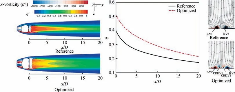
Fig. 6 Comparisons of film cooling contours, laterally averaged cooling effectiveness and streamlines and x-vorticity distributions between reference and optimized laidback fan-shaped hole.38
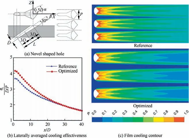
Fig. 7 Geometry of novel shaped hole and comparisons of film cooling contours and laterally averaged film cooling effectiveness between reference and optimized geometries.40

Fig. 8 Geometrical variables of double-jet film cooling hole and film cooling contours for reference and optimum shapes.44
Chi et al.optimized the geometry of a tripod cylindrical hole with asymmetrical side holes by using the DOE method.Then they experimentally validated the optimum configuration via the PSP technique by comparing its experimental results with those of a simple cylindrical hole and a shaped hole.Concerning the optimization process, the optimization objective was the area average film cooling effectiveness, and the four dimensionless design variables were the streamwise distance between the exits of two side holes, the streamwise distance between the exits of the middle hole and one of the side holes,the averaged spanwise location of the exits of two interacting side holes relative to the neighboring middle hole and the spanwise distance between the exits of two side holes. The results showed that for the same flow condition,the optimized tripod cylindrical hole provided slightly better film cooling performance than the shaped hole and considerably higher cooling performance then the simple cylindrical hole. However, it was found that the film cooling effectiveness of the optimized asymmetric tripod hole decreased faster than the shaped hole along the streamwise direction at a high blowing ratio.
Chi et al.also performed a two-level design optimization to enhance the film cooling performance. In this study, GA coupled with a metamodel was applied to find the optimal geometries of the shaped hole exit with and without a compound angle on a flat plate at a blowing ratio of 1.0 and density ratio of 1.5. The hole exit was initially modeled using Bspline curves with a binary parameter. The metamodel was chosen to well predict the film cooling effectiveness of the shaped holes. The results showed that the optimal shaped holes could provide higher film cooling performances due to the generation of a back flow vortex which weakens the mixing of the hot gas and coolant. Fig. 9compares the film cooling contours and the laterally averaged film cooling effectiveness for the prototype and the optimized geometry.
Similar methods,i.e.,GA together with the metamodel,were adopted by Ref.48 to optimize a narrow and angled trench film cooling hole. The two objective functions of the optimization problem were the maximization of the spatially averaged overall cooling performance and the reduction of the standard deviation of the cooling effectiveness for homogeneous coolant distribution. The trench depth and the locations of the four trench edges were varied as optimization parameters. Furthermore,the Radial Basis Function (RBF) was selected as the response surface model. The responses at the design points were calculated by using a hybrid scale adaptive simulation. At the end,Infrared thermography (IR) was applied to validate the optimized configurations, which realized a 45% enhancement of the spatial averaged film cooling effectiveness.

Fig.9 Comparisons of film cooling contours and laterally averaged film cooling effectiveness for prototype and optimized geometry.47
Huang et al.firstly conducted optimization of the round-to-slot holes. Both single-objective optimizationand multi-objective optimizationwere carried out in their work.In the single-objective problem, the spatially averaged film cooling effectiveness was used as objective function and CFD analysis with the RBNN model and GA method were utilized to find the optimal structure. On the other hand, in the multi-objective problem, the discharge coefficient and the spatially averaged film cooling effectiveness were chosen as the two independent objective functions. Similar optimization methods but NSGA-II was selected to search the Pareto front of the optimal solutions. By comparing these two studies, it was indicated that there was a tradeoff between the two objectives,and the optimal solutions of these studies provided many options for designers in this field.
wIt can be seen from the above optimization works that surrogate models, like RSA, KRG, RBF, RBNN, SVM and WTA, are widely used in optimization to construct the surrogate for the objective functions. In addition, the optimization results have a direct relationship with the accuracy of the surrogate model.However,the accuracy of the surrogate model is seriously limited by the selection and quantity of the design points.Besides,a lot of efforts are required to construct a surrogate model. Therefore, many other methods, like Taguchi method,Curve Fitting Method (CFM), Principal Component Analysis (PCA) method and Proper Orthogonal Decomposition(POD)method were used in the optimization works to present more accurate predictions for the objective function and to improve the optimization efficiency.
Wang et al.adopted the Taguchi method to optimize the parameters of a backward cylindrical hole to enhance the film cooling performance.The influences of the blowing ratio,inclination angle and hole length on film cooling performance were studied. Moreover, a three-factor four-level orthogonal scheme was designed to find the optimal design point with less computational effort. The results showed that compared with the forward hole, the backward hole presented significant improvement of the film cooling effectiveness at a blowing ratio of 2.0.The optimal hole configuration was also obtained at this blowing ratio with an inclination angle of 35°and a hole length of 3D.Fig.10presents comparisons of velocity vector,streamlines of the jet flow and the film cooling contours for the case before optimization and the optimized one.
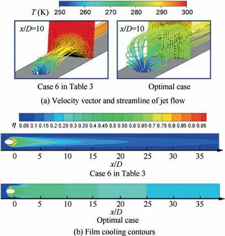
Fig. 10 Comparisons of velocity vector, streamlines of jet flow and film cooling contours for Case 6 and optimal case.52
CFM is intended to find an exponential or polynomial function to fit the numerical simulations results. The evaluation of objective function values by using CFM is beneficial to save the computational effort. Taheri et al.adopted RANS analysis with CFM and GA to optimize the angles of three rows of film cooling holes to improve their film cooling performance and reduce the aerodynamic loss. It was figured out that when the angles of the three rows of film cooling holes were,respectively,25.45°,32.85°and 33.1°,the performance of the design point was the best. The same methodologies were employed by Moeini and Rajabi Zargarabadito optimize the laterally diffusion hole over a rotating blade for better area average cooling effectiveness.
PCA is a method,which converts high-dimensional data to low-dimensional ones and is a tractable one but it does not lose too much information by analyzing the dependencies between the variables.Due to this,the methods based on PCA or statistic methods of PCA are useful to help reducing the computational demand. Vinogradov et al.developed a method for film cooling holes optimization by using structurallyparametrical analysis of the empirical data. PCA based methods to compress and transform data and a random search method were employed. It was demonstrated from the results that the proposed method reduced the computational expenses by 8-10 times. In addition, the developed surrogate model during the optimization process provided an accurate prediction of the film cooling effectiveness. Fig. 11depicts the laterally averaged film cooling effectiveness and velocity vectors with dimensionless temperature contours of traditional fanshaped hole and optimized hole.
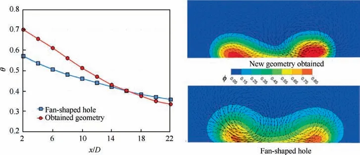
Fig. 11 Comparisons of laterally averaged film cooling effectiveness and velocity vectors with dimensionless temperature contours for traditional fan-shaped hole and optimized hole.55
POD is a PCA method, which also can be used to reduce parameters’ numbers and therefore saved the computational time. Nita et al.adopted the POD method coupled with RSA and CFD to optimize the hole shapes and improve the film cooling effectiveness. In this study, the POD approach was used to decompose 18 basic film cooling hole shapes into 5 shape parameters, and then reconstruct these parameters to generate new hole shapes. The optimization results showed that compared with the traditional round hole and fanshaped hole, the optimal hole provided 14 times and 4 times higher film cooling effectiveness, respectively.
Elsayed et al.applied numerical computations of the compressible viscous flow equations and the simplex algorithm to conduct optimization of film cooling parameters. Five parameters including streamwise angle,blowing ratio,lateral and forward diffusion angles and inlet velocity direction were taken into consideration.After the optimization process,the optimal cooling parameters were selected to provide maximum overall film cooling effectiveness of a laidback fan-shaped hole.
A gradient based framework was considered by Madrane et al.to optimize the inclined hole shapes. In contrast to the above studies,the boundary of hole shapes in this work was controlled by many points with coordinates.A method called Moving Asymptotes was selected as optimizer to find the optimal shapes based on the initial hole geometries.The adjoint method was used to compute the gradients during optimizations.
All the investigations on optimization of film cooling hole shapes in the above references were conducted on flat plates.Table 1 summarizes the optimization information involved in the above references, including optimization objectives, objective functions, design of experiments methods and optimization methods. In addition, there are plenty of optimization works of film cooling hole shapes conducted on turbine blades or vanes, which will be reviewed in the following part.
2.2. Film cooling optimizations conducted on turbine blades or vanes
2.2.1. Optimizations of film cooling holes on leading edge
The leading edge of a turbine blade is exposed to hot gas of very high temperature, which makes it is subject to very high heat loads. In order to prolong the lift-time and increase the durability of turbine blades, impingement cooling and film cooling have been utilized at the leading edge region to reduce its temperature. Some worksfocused on optimizing the film cooling structures placed at the leading edge portions of an High Pressure Turbine (HPT) blade. Garcı´a et al.conducted film cooling optimization on the leading edge of a gas turbine blade model, with a showerhead configuration, by varying hole pitch,diameter,injection angle,column hole pitch and velocity at the plenum inlet.RANS computations coupled with Artificial Neural Networks (ANN) and Differential Evolution (DE) algorithm, which is a relative new EA method developed by Storn and Price,were utilized to increase the area averaged film cooling effectiveness and to reduce the coolant flow consumption, simultaneously. Fig. 12compares the film cooling effectiveness at the leading edge between an optimal specimen and the best specimen of the initial database.Results showed that the area averaged film cooling effectiveness was increased by 36% while the coolant mass flow was reduced by 66% for the optimal structure.
Mostofizadeh et al.constructed a CFD-ANN-GA optimization loop to optimize the hole position, diameter, spacing and injection angles on the leading edge of a vane of real geometry with an internal cavity for better film cooling effectiveness. Results showed that the vane temperature of the optimal design was decreased considerably, while the coolant consumption was increased. Therefore, to compensate this disadvantage of the optimal design, a 100 μm thermal barrier coating was covered on the external surface of the vane.
2.2.2. Optimizations of film cooling holes on pressure side
Johnson et al.are the pioneers to perform optimization of film cooling design for a realistic HPT vane.Theycarried out a design and optimization of a film cooling array on the pressure side of a nozzle guide vane. Five design variables, including injection angle, compound angle, cooling hole size, row pattern and two-dimensional surface hole location on the vane pressure side, were varied in the design space. GA together with LHS method and three-dimensional RANS simulation were utilized to maximize the cooling effectiveness and minimize the area averaged heat transfer over the pressure surface.As indicated in Fig.13,improvement of the film cooling performance of the turbine vane pressure side was realized by theoptimal design, which could also potentially reduce the temperature extremes and increase the engine efficiency.
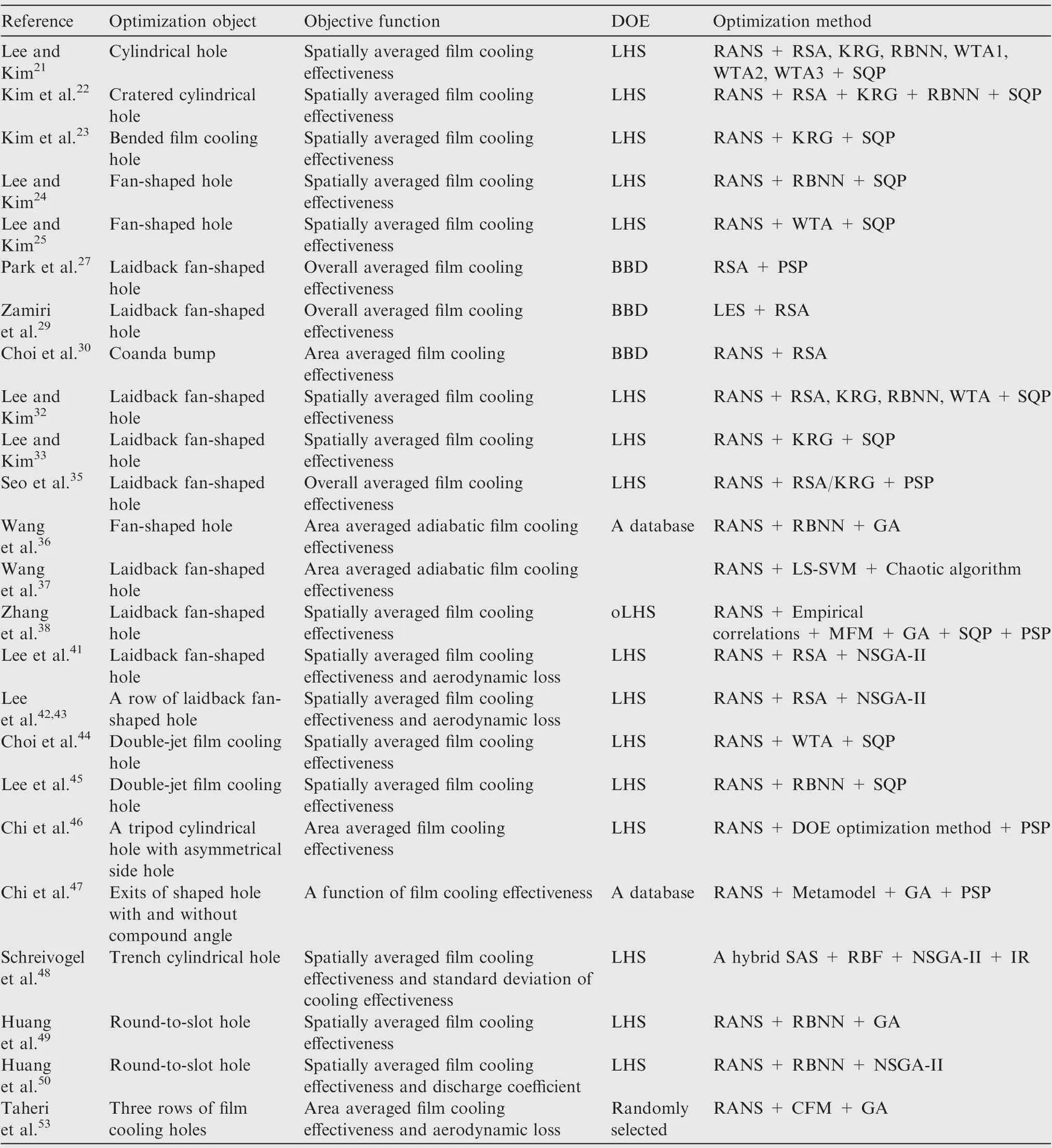
Table 1 Optimization information of hole shape optimizations conducted on flat plates.
Different from Johnson’s works,which focused on optimizing the hole parameters,Lee et al.focused on optimizing the arrangement of three film cooling hole arrays on the pressure side surface of a nozzle guide vane. The array shapes of the film hole were dominated by five design variables using a newly developed shape function. RANS analysis with KRG and GA were employed as the optimizer. To guarantee the accuracy of the KRG model, the expected improvement given by the following Eq.(1),suggested by Schonlau,was used as a selecting criterion for additional sampling points.
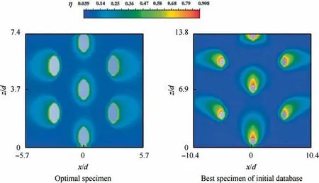
Fig. 12 Film cooling effectiveness distributions at leading edge between optimal specimen and the best specimen of initial database.60
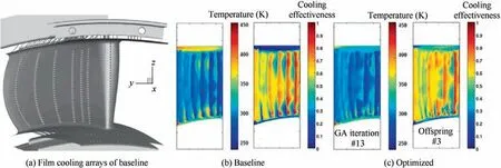
Fig. 13 Schematic of film cooling arrays on pressure side of turbine vane and comparisons of temperature and cooling effectiveness distributions for baseline and optimal design.63

where x is the sampling point;yis the value at sampling point x,which is evaluated by Kriging model;I is an all 1 vector that has the same dimension as x; frepresents the minimum value among n sampled values;s is the root mean square error of the predictor for the KRG model;Φ and φ are the standard normal distribution and standard normal density,respectively.With respect to the optimum hole array shapes, reductions of 10.1%, 27.1% and 45% were, respectively, achieved for the averaged wall temperature,temperature deviation,and coolant mass flow after the optimization process. An experimental study was performed to validate the optimization results in Ref. 67. Later, they carried out similar optimization work in Ref. 68.
In addition, Lee et al.conducted further optimization works on the arrangement of film cooling holes on the pressure side of an HPT nozzle.For the first time,both the manufacturing tolerance and cooling performance were simultaneously considered because the manufacturing tolerance has substantial influence on the cooling performance of the film hole. To tackle this problem, probabilistic process coupled with optimization process was performed. In detail, the probabilistic process was composed of the KRG model and Monte Carlo Simulation (MCS) with a descriptive sampling method.Besides,GA was selected as the searching method.The Pareto front and the optimum configurations obtained through these procedures are given in Fig. 14.Results showed that the maximum improvement of expectation and variance of the cooling performance were 7.66% and 62.53%, respectively.The same processes were adopted to optimize the Nekomimi hole,which was defined by 4 design variables, and partial hole block, in-hole roughness and blade surface roughness were all considered.The results showed that the hole blockage had the most significant uncertainty, while the in-hole roughness and surface roughness had a certain effect separately,on the mass flow rate and cooling performance. Therefore,to mitigate the effect of hole blockage, the hole shape of the optimized design had been enlarged.

Fig. 14 Pareto front and optimum designs.70
In most optimization studies of the arrangements of film cooling arrays, like Refs. 68-70, Conjugate Heat Transfer(CHT) has been ignored since it necessitates heavy computational demands and complexity. To tackle this problem when considering CHT, a variable-fidelity surrogate model, i.e., a hierarchical KRG model, which was suggested by Han and Go¨rtz,was utilized by Kim et al.In this work, a threelevel hierarchical KRG model was established using a fewer number of CHT analysis constituting the higher fidelity model and the large number of adiabatic-condition-based analysis constructing the two lower fidelity model.It was demonstrated that the computational time was considerably reduced with the usage of the three-level hierarchical KRG model during the optimization process. In addition, the results showed that the overall cooling performance of the CHT-based optimal hole array was better than that of the adiabatic condition-based optimal hole array.
2.2.3. Optimizations of film cooling holes on suction side
Single and multiple objective optimizations of discrete film cooling holes on the suction side of a turbine vane were carried out by El Ayoubi et al.Theyperformed thermal optimization, aero-thermal optimization and aerodynamic optimization of the cooling hole to achieve a maximum of the adiabatic film cooling effectiveness and a minimum of the aerodynamic penalty by varying the total pressure ratio and coolant to mainstream temperature ratio.The results indicated that the optimization method utilized in this work was a reliable tool for film cooling in real applications. In addition,theyalso performed optimization of the film cooling hole to realize the same objectives but by varying the compound angle, conical expansion angle, and the length to diameter ratio of the non-diffusing portion of the hole. Fig. 15 shows the two-dimensional details of the vane and film cooling configuration.In addition,non-dimensional temperature contours along the centerline of the first and second rows of the optimized cases are also given in Fig. 15.It was found from this study that the thermal optimal structure provided over 100%improvement of the cooling performance and 22% reduction of the aerodynamic loss while the aerodynamic optimal structure could further reduce the aerodynamic loss with a relatively lower improvement of the cooling performance. These two studies adopted the same optimization methods, i.e., the GA coupling with an ANN. In their previous study,the same optimization methods were adopted for film cooling holes on the suction surface of the VKI rotor. Huang et al.also performed an optimization study on the suction surface of a turbine vane. Their optimization objectives were to maximize both the discharge coefficient and the spatially averaged film cooling effectiveness of laidback fan shaped holes. The optimization methods used in this work was the same as those adopted in their previous work. The results showed that,compared with the reference geometry, the discharge coefficient and the spatially averaged film cooling effectiveness of the optimal case were increased by 10.5% and 1.6%, respectively, when considering these two objectives.

Fig. 15 Two-dimensional details of vane and film cooling configuration and non-dimensional temperature contours of optimized cases.75
2.2.4. Optimizations of film cooling holes on leading edge,suction and pressure sides
Based on investigations of Johnson et al.,Yin and Fangconducted optimization of the film cooling holes (injection angle and streamwise position of holes) of the first high pressure stage of GE-E3 to reduce the maximum and average blade temperatures. The overall film cooling effectiveness at each design point was simulated by using the source term method,which was much cheaper than the CFD calculation. In addition, NSGA-II was employed to search the optimal design.Results showed that the optimal design could provide better temperature distribution compared with the reference one.Besides,it was found that the film hole on the suction side performed worse than that on the pressure side.
Jiang et al.carried out aero-thermal optimization on multi-rows film cooling of a realistic marine HPT vane by using a full 3-D optimization platform. The objectives of this work were to maximize the film cooling effectiveness and minimize the aerodynamic loss.The LHS method coupled with the three-order RSA method and Multi-Island GA or NSGA-II was utilized to solve the single- and multi-objective optimization problems. The results showed that the film cooling improvements of three considered cases for single-objective optimizations were 8.1%, 7.4%, 7.0%, respectively, while the aerodynamic efficiency improvements of these three cases were 0.046%, 0.057%, and 0.069%, respectively. Due to the tradeoff between the two objectives, the cooling effectiveness improvements of two cases for multi-objective optimizations were 11.4% and 1.5%, respectively, while the aerodynamic efficiency improvement was maximum 0.0966%.
Later,Jiang et al.adopted the same platform to optimize the multi-rows film cooling of a C3X turbine vane,as shown in Fig. 16(a).
Design variables including the hole space and compound angles of the film holes on the leading edge and injection angles of film holes on the suction and pressure sides were decided through a sensitivity analysis. Multi-Island GA was employed to optimize the objective,i.e.,the averaged adiabatic film cooling effectiveness.It was illustrated from Figs.16(b)-16(d)that the cooling effectiveness was improved by 8.4%, 5.5% and 1.1%, respectively, at the leading edge region, pressure and suction surfaces through the optimization procedure. Besides,the average temperature was reduced by 19 K on the leading edge region. Mu¨ller et al.adopted the evolution strategies to optimize the film cooling of a typical vane. Not only film cooling but also impingement cooling and trailing-edge geometry for convection cooling were considered in the vane. During the optimization process,the optimization objective was to minimize the mass flow of the coolant with the constraints of mean, minimum and maximum outer surface temperature.The position of the film hole rows, the holes’ injection angles,the number of holes per row,the number of impingement holes and the loss parameter, which was a function of the pressure loss in the trailing edge, were selected as design variables.The optimized results suggested that five rows of film holes should be placed in the leading edge and two rows on the pressure side.
2.2.5. Optimizations of film cooling holes on other components
Viana et al.performed a multi-objective optimization of film cooling based on temperature in gas turbine hot gas path components using the goal attainment method, which does not generate a Pareto front but converts the multi-objective to a single-objective optimization problem with constrains. Three variables including the cooling hole diameter, film row placements and hole to hole spacing were varied to try to reduce the maximum metal temperature by using less cooling flow.To alleviate the computational effort during the optimization process, design of experiments and RBF were adopted. The optimization results improved the distribution of temperature and reduced the usage of the cooling flow.
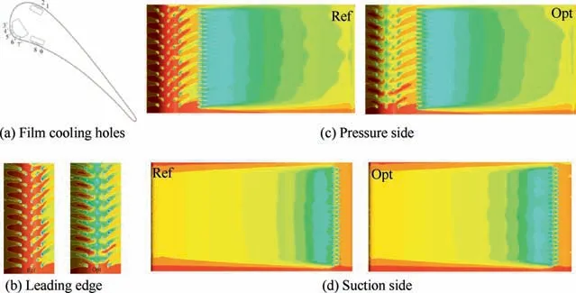
Fig. 16 Schematic of film cooling holes and comparisons of dimensionless temperatures on leading edge, pressure and suction surfaces for reference and optimized geometries.80

Table 2 Information of film cooling optimizations conducted on turbine blades or vanes.
All the above film cooling optimization works were conducted on turbine blades or vanes, i.e., the effects of surface curvature and pressure gradients on the film cooling effectiveness was considered. Table 2 outlined the optimization methods utilized in the above references. It was found that RANS analysis coupled with surrogate models and evolution algorithm,i.e.,DE,GA,NSGA-II was the widely adopted method for film cooling optimization performed on turbine blades or vanes.In addition,it was indicated that surrogate models have the potential to further reduce the computational time during the optimization process.
3. Optimizations of internal cooling
Internal cooling is another main cooling technique adopted inside the gas turbine blades. The heat transfer performance in the internal cooling channel is strongly influenced by the parameters of the cooling structures. For instance, the rib angles, heights, and pitches have big influences on the cooling performance, besides, different dimple diameters, depths, and pitches lead to different heat transfer performance. Besides,the aerodynamic performance and averaged temperature of a turbine vane strongly depend on the shape and position of the internal cooling passages. Therefore, many optimization investigations were conducted subsequently to figure out better internal cooling designs and these will be reviewed in the following subsections.
3.1. Optimizations of jet impingement cooling structures
Jet impingement cooling is widely adopted in cooling the leading edge regions of the turbine blades because its high convective heat transfer coefficient and large flow resistance. Chi et al.carried out several optimizations on impingement cooling structures for higher cooling performances and aerodynamic performances. Theyfirst focused on optimizing both impingement and pin-fin cooling structure on the vane.Parameters including the size of impingement tube, the diameter and distribution of impingement holes, and the size and distribution of pin-fins were varied during the optimization process. A Single-Objective Genetic Algorithm (SOGA), a mesh generation tool (Coolmesh) and a CHT solver were forming an optimization platform to optimize these cooling structures. Later,a novel Anti-CrossFlow (ACF) impingement tube with nonuniform structure on the leading cavity of a vane was chosen as the optimization object. Fig. 17(a)presents the schematic of the novel impingement tube in the 2nd stage vane of a gas turbine. The location and diameter of the holes were selected as the variables.A two-level strategy with CHT analysis,metamodel and a single-objective gradientbased GA was adopted to optimize the impingement cooling structure. Results showed that a more uniform wall temperature distribution was achieved with a limited coolant flow rate,which is indicated in Fig. 17(b)and Fig. 17(c).
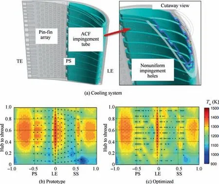
Fig.17 Schematic of cooling system with ACF impingement tube and nonuniform impingement holes and comparisons of impingement cooling hole arrangements and wall temperature distributions for prototype and optimized designs.85
A two-level optimization strategy with both SOGA and Multi-Objective Genetic Algorithm (MOGA) was employed on a nonuniform impingement cooling structure proposed in Ref.85 under a nonuniform thermal load.This work was also conducted by Chi et al.Compared with the single-objective optimization search, multi-objective optimization could provide many optimal cooling designs at various coolant flow rate. It was found that the averaged wall temperature of the impingement surface had limited reduction by increasing the cooling flow rate. In addition, the improvement of the overall cooling performance mainly depended on the temperature reduction at the pin-fin array. After this, theyconstructed an optimization platform to reduce the wall-temperature and to enhance the aerodynamic performance of the impingement-film cooling structure on the endwall of a gas turbine. Results showed that the cylindrical film holes near the throat led to better cooling and aerodynamic performance.Moreover, the optimal space of the impingement array was designed to eliminate the jet lift-off of the film coolant.
Farahani et al.conducted an optimization of two impinging slot jets to achieve a uniform convective heat transfer coefficient distribution over a flat plate.The pattern search method was utilized as the optimization method to minimize the root mean square deviation of the local Nu distribution from desired Nu. The optimizations were performed both in steady state and pulsating state. Results showed that the variance of the uniform heat transfer coefficient was less than 0.01%through optimization in the pulsating state.
Inspired by the Micro Cooling Concepts, Jacobs et al.designed an impingement cooling surface with micro-texture for better impingement cooling effectiveness.Four microstructures were considered including groove,shrouded groove,strip fin, and shrouded fin. A trust-region algorithm coupled with an active-set algorithm and numerical simulations was used to optimize these four structures to achieve lower metal temperature. It was found that the shrouded fins and fin design performed better than other designs. In addition, though the maximum temperature of the external free stream was 2600 K, the maximum temperature of the internal vane temperature was less than 1219 K.
3.2. Optimizations of rib shapes in cooling channels
Ribbed channels belong to the widely applied passive heat transfer enhancement techniques.Accordingly,many researchers focused on rib shape optimizations in turbine cooling channels for better heat transfer performance. Kim et al.first carried out an optimization of a two-dimensional channel with a single surface roughened with ribs by using the RANS analysis coupled with the gradient based numerical optimization technique. Two dimensionless parameters including width-toheight ratio and pitch-to-height ratio of the rib were used as design variables to maximize the heat transfer and minimize the friction loss. To solve this multi-objective optimization,an objective function combining these two objectives with a weighing factor was defined as follows,

where β is the weighting factor,and it is varied by considering different overall energy economy of the system. Fis the inverse of the averaged Nusselt number,
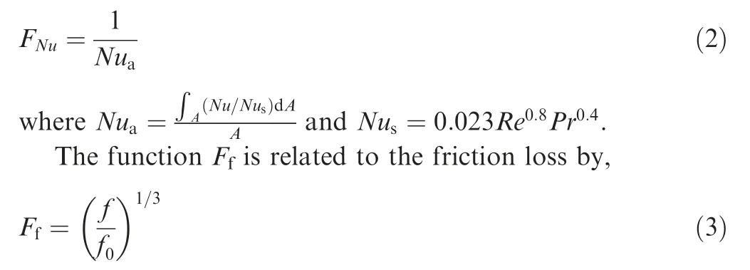
where f is the friction factor; f= 2(2.236lnRe - 4.639). In this work, β was equal to 0.05 and 0.1. The optimization results proved that the numerical optimization technique coupled with RANS analysis was a promising tool to find the internal cooling surface with better thermal performance.
Later Kim et al.performed an optimization of the shape of ribs mounted on both walls of a two-dimensional channel.Compared with their previous work,two additional design variables, i.e., rib height to channel height ratio and distance between opposite ribs to rib pitch ratio were selected, and RANS analysis coupled with RSA method was adopted to find the optimal shape of the channel with ribs.However,the objective function designed in this work was the same as in the previous work,and the weighting factor β in the function was varied in the range of 0 to 0.1.The results validated that a global optimization method RSA was superior to the gradientbased methods. Besides, the RSA method coupled with the RANS analysis method was much more reliable and economic for optimizing the cooling channel.
Subsequently, theyused the same method to optimize the shape of a three dimensional channel with angled ribs placed on a single wall to improve the heat transfer performance. In this work, the optimization objective was the same as in the previous studies. The range of the weighting factor β was 0 to 0.1. The two design variables were width-to-rib height ratio and rib attack angle. The results showed that the optimal points depended on the values of β.To be more specific, the increase of β resulted in a larger optimal value of the width-to-rib height ratio but a smaller rib attack angle.
Haasenritter and Weigandoptimized the rib structure in a 2-D cooling channel by using SOGA and MOGA to validate the usefulness of these methods for optimizing a simple 2-D geometry. Two objectives, i.e., heat transfer performance(Nu/Nu) and thermal performance ((Nu/Nu)·(f/f)) were selected for optimization.Rib heights, widths,distances, inner pitch distance and channel length, as shown in Fig. 18(a),were chosen as design parameters. Fig. 18(b)presents the Pareto-optimal front at different Reynolds numbers. It was demonstrated from the study that the basic approach used in this work was useful and promising to be extended to a 3-D real geometry.
Based on their own work,Kim et al.extended the optimization to a three dimensional channel with angled ribs mounted on both walls by adopting the same optimization methods. In addition, in this work, except for the rib pitchto-height ratio and the rib height-to-channel height ratio, the rib attack angle and the streamwise rib distance on the opposite wall to rib height ratio were also chosen as design variables. It was suggested that designers should increase the rib pitch-to-height ratio and ribs displacement-to-height ratio but decrease the rib attack angle and the rib height-tochannel height ratio to reduce the friction loss of the channel.A similar optimization work was carried out by Yang et al.in a square cooling channel,however,they focused on varying rib angles, rib width-to-channel diameter ratio and rib pitchto-channel diameter ratio to maximize the thermal performance factor E, which was defined as follows:

The results showed that a thermal performance enhancement of 20% was achieved by the optimal geometry.
Xi et al.performed optimization work on steam-cooled ribbed channels by using Back Propagation Neural Network(BPNN) coupled with GA. In addition, the channel geometric parameters shown in Fig. 19(a),including channel aspect ratio, rib attack angle and Reynolds number, were adopted to fit the semi-empirical heat transfer correlation. The investigations were also carried out to optimize the BPNN model. It was found that the optimized BPNN depicted better prediction accuracy than the fitted correlation. Later, the optimized BPNN with GA was utilized to optimize the channel aspect ratio and rib angle to achieve better heat transfer performance.Fig.19(b)illustrates the superiority on Nusselt number of the optimized channel compared with the non-optimized channel.
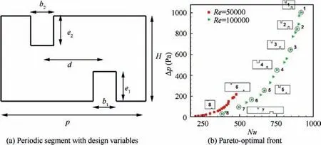
Fig. 18 Periodic segment with definition of design parameters and Pareto-optimal front for Re = 50000 and Re = 100000.94
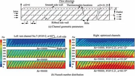
Fig. 19 Schematic of channel geometric parameters and comparisons of heat transfer performance for optimized and non-optimized channels.97
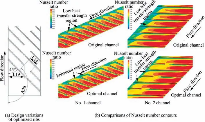
Fig. 20 Design variables of optimized ribs and comparisons of Nusselt number contours of original channel and optimal channel for No. 1 and No. 2 channels.98
Zhu et al.also presented an optimization work on angled ribs. However, in this work, the attack angle of the rib was fixed as 45°. The optimization object was a part of a rib removed from the original rib. The aim of this optimization work was not only to reduce the channel friction loss but to enhance the heat transfer of the region behind the terminal side of the angled rib to increase the uniformity of the channel temperature. Therefore, three removed rib parameters including its length, its transverse location and the angle between the incision edge and the flow direction were selected as design variables, as shown in Fig. 20(a).The KRG together with MOGA was applied to solve this problem. Fig. 20(b)compares the Nusselt number contours of the original channel and optimal channel for the No. 1 and No. 2 channels. It was found that removing the inefficient rib parts of angled ribs was beneficial to maintain or enhance the heat transfer and further reduce the friction loss.
A novel boot-shaped rib was proposed and optimized in a cooling channel by Seo et al..The RANS analysis with a surrogate model and MOGA was adopted to optimize the multiobjectives, i.e., area-averaged Nusselt number, and friction factor. Four dimensionless ratios including tip width-to-rib width ratio, rib width-to-height ratio, rib height-to-channel height ratio and tip height-to-rib height ratio were selected as design variables. In this work, two surrogate models, RSA and KGR, were taken to compare their convergence and spread performance. The results showed that the RSA model exhibited good convergence behavior but poor spread ability.
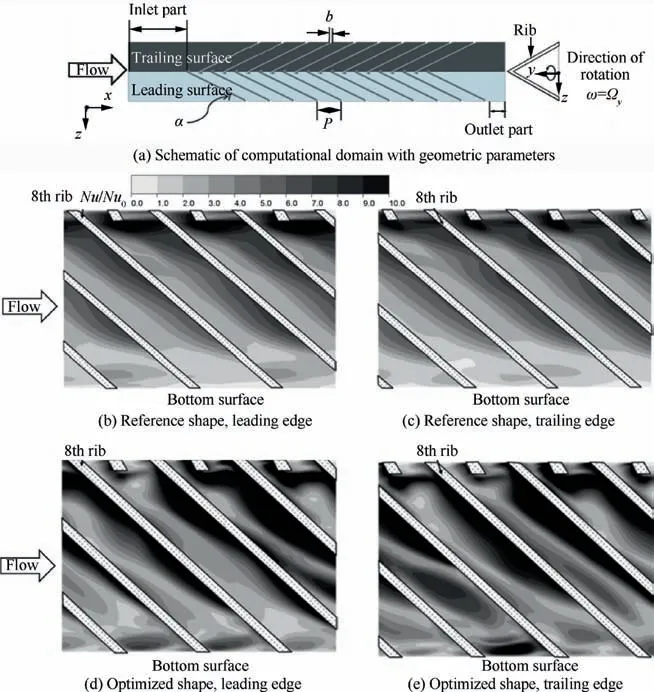
Fig.21 Schematic of computational domain with geometric parameters and Nusselt number contours of leading edge and trailing edge for reference and optimized shapes.105
In addition, many research works like Refs. 100,101 demonstrated the superiority of V-shaped ribs compared to other square rib shapes and arrangements.To further enhance the heat transfer performance of V-shaped square ribs extruded on both walls of a square channel, Kim and Leeconducted an optimization work on it by using RANS analysis with RSA optimization method. They varied rib pitch-toheight ratio, rib height-to-channel height ratio and rib attack angle to minimize the objective function, which was a linear function of Nusselt number and friction loss as shown in Eq. (1). Nagaiah and Geigerpaid attention to the automated optimization of semicircular ribs in a cooling channel to enhance the heat transfer and reduce the pressure drop.Multi-objective NSGA-II combined with the numerical simulation software COMSOL was utilized as optimizer. Later,theycarried out a similar optimization work, but considering the maximization of the cavity area of the cooling passage as the third optimization objective. The reason was that by increasing the cooling passage cavity area,the expensive material used for blade fabrication will be minimized.
Moon et al.shifted the optimization focus on a rotating equilateral triangular channel with staggered square ribs, as shown in Fig. 21(a).An equilateral triangular channel is a typical channel inside the leading edge of a turbine rotor blade.Rib angle, rib width-to-channel hydraulic diameter ratio and rib pitch-to-channel hydraulic diameter ratio were selected as design variables to construct the RBNN surrogate model of the objective functions.Figs.21(b)-21(e)present the Nusselt number contours of the leading edge and trailing edge for the reference and optimized geometry. In this work, the objective function utilized was the same as that in Ref. 102. Finally,21.5% improvement of the objective function was achieved by the optimal channel.
A novel mesh morphology based optimization tool called RBF4AERO was adopted by Kiyici et al.to optimize the cross-section of the last rib mounted on the first section of a U-turned channel. There were two sub-routines included in the optimization process. The first routine was to use the RBF-Morpher to generate new rib cross-section geometries and sample the design space while the second routine was to utilize the RSA based optimization method to find the optimal design. The results showed that the tooth type rib geometries presented better heat transfer performance and lower pressure drop than the rectangular rib geometries. In addition, it was found that the enhancement of the heat transfer by the optimal rib was only occurring upstream the turn section.
3.3. Optimizations of dimple shapes in cooling channels
After focusing on optimization of rib shapes in cooling channels, Kim et al.shifted their focus on optimization of dimples shapes. Theyfirstly carried out an optimization of in-line dimple shapes on a single surface of the channel to enhance the turbulent heat transfer and reduce the friction loss of the cooling channel. Three dimensionless parameters, i.e.,channel height to dimple print diameter ratio, dimple depth to dimple print diameter ratio and dimple print diameter to dimple pitch ratio were chosen as design variables.RANS coupled with the RSA method was adopted as the optimizer.Fig.22,depicts the dimple channel geometry and the design variables and compares the Nusselt number and friction factor of the reference and optimized designs.
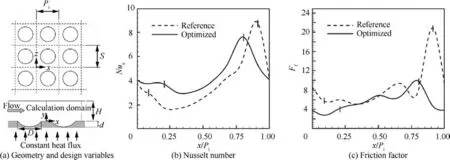
Fig. 22 Schematic of dimple geometry and design variables and comparisons of Nusselt number and friction factor for reference and optimized geometry.107
Later, theyperformed optimization of staggered dimple shapes with the same optimization objective by considering the same design variables as in their previous work. However,in this study,the optimization technique based on RANS coupled with KRG was utilized as optimizer and the SQP algorithm was adopted to find the optimal point within the design space.The results of these studies showed that the shape optimization of dimples enhanced the heat transfer of the channel and the optimal shape of the dimple was found by varying the weighting factor.
Inspired by the optimization work in Ref. 108, Samad et al.conducted a series of optimization works on a staggered dimpled channel to assess the performance of different surrogate models, including KRG, RSA, RBNN and WTA.Except for the surrogate model, the same optimization objective function,same DOE method and same optimization algorithm were used as those in Ref. 108. The results showed that the WTA model was the most robust and reliable model in the predictions. Later, theyperformed single- and multiobjective optimization works on the same channel. The RSA method was utilized to construct the surrogate model of the objective functions. For single-objective optimization, SQP was chosen to find the optimal point. However, for multiobjective optimization, MOGA was used to find the Pareto optimal front. They concluded that multi-objective optimization was superior to single-objective optimization as it provides many optimal designs for designers. The above two works focused on staggered dimples on a single surface of the cooling channel. As shown in Fig. 23(a), Samad et al.also optimized staggered dimples, which were printed on both walls of the cooling channel by using RANS analysis and RSA surrogate model with the hybrid multi-objectively evolutionary algorithm NSGA-II. It was demonstrated that strengthening the flow vertical motion and shortening the dimple reattachment length were beneficial to enhance the channel heat transfer.In addition,it can be seen from Fig.23(b)that the thermal performance was augmented by the optimization.
The above optimization works were conducted on cylindrical dimples,while in Ref.112,Kim et al.paid attention to optimize staggered elliptic dimples in a cooling channel. Three non-dimensional parameters, i.e., d/d, H/dand S/P, of elliptic dimples were varied to enhance the heat transfer and reduce the pressure drop of the dimpled channel. Here, dwas the dimple average diameter and d= (d+ d)/2. The same optimization methods but a different surrogate model KRG was employed in this work compared with the previous work of Samad et al.After this work, Kim et al.performed the optimization on inclined elliptic dimples in a cooling channel. Expect for the two above mentioned nondimension variables d/dand H/d, the angle of the ellipse major axis to flow direction (α) was also chosen as a design variable. In this work, the adopted optimization objective and optimization method were the same as those utilized in Ref. 105.

Fig.23 Illustration of geometry and design variables and comparison of thermal performance for reference and two optimized cases.111
3.4. Optimizations of pin-fin arrays in cooling channels
Pin-fins are usually arranged into arrays and extended between two opposite walls of an internal cooling channel to significantly augment the heat and mass transfer. Many existing literatures focused on investigating the influences of Reynolds number, pin geometry, pin-fin arrangement configuration and other parameters on heat transfer and pressure drop in the pin-fin channel. To further enhance the turbulent heat transfer and thermal performance, shape optimizations of the pin-fin arrays were carried out by many researchers.
Li and Kimperformed a multi-objective optimization of staggered elliptic-shaped pin-fin arrays to augment heat transfer and reduce friction loss. Four dimensionless design variables, i.e., H/D, 2a/D, 2b/D and P/D were selected, and the D-optimal method was used to sample the design points in the design space.Fig.24(a)presents the calculation domain and geometric parameters of pin-fin arrays. The methods adopted in this work for shape optimization and flow analysis were the same as those employed in Ref.. The Paretooptimal solutions obtained by using NSGA-II, ε-constraint and clustering were shown in Fig. 24(b).
Later,Moon et al.carried out a series of optimization work on pin-fins by using the same methods for flow analysis(i.e.,RANS analysis) and optimization (multi-objective evolutionary algorithm NSGA-II with local search method SQP).In addition, the optimization objective functions of these three works were the same. Firstly, theyfocused on staggered pin-fin arrays in a rotating rectangular cooling channel.Then,theyput the pin-fin arrays in the second passage of a twopass rectangular channel to optimize their shapes. In these two works, the same dimensionless design variables, i.e.,streamwise distance between pin-fins to pin diameter ratio and channel height to pin diameter ratio,were chosen.Finally,theyproposed and investigated the heat transfer performance of a novel fan-shaped pin-fin and compared it with the traditional circular pin-fin. Fig. 25(a)gives the schematic configuration of a novel fan-shaped pin-fin. It was demonstrated from Fig. 25(b)that a significant improvement of heat transfer was achieved by the fan-shaped pin-fin compared with the circular one.To further explore the unearth heat transfer potential of a fan-shaped pin-fin,an optimization work was conducted on it in a rectangular channel by varying design variables R/Rand θ. In these three studies, three different surrogated models, i.e., KRG model, RSA model and RBNN model were, respectively, employed to construct the surrogates for the objective functions during the optimization processes. As shown in Fig. 25(c),one of the optimized designs, i.e. design A, was selected to show its superiorities compared with the reference fan-shaped pin-fin.
3.5. Optimizations of U-bend shaped cooling channels
A U-bend channel is a typical structure which turns the flow through 180°in a modern turbine blade cooling system.Therefore, it is common to investigate the heat transfer and fluid flow characteristics inside the channel with and without the different turbulators. In addition, several optimization works have been carried out to optimize the shapes of U-bend channels to minimize the friction loss of the channel.
Namgoong et al.minimized the static pressure difference between the planes PLand PLof a U-bend channel by optimizing the shape of the inner wall. To reduce the computational loss during the optimization process, the KRG surrogate model and GA method were utilized as the optimization methods. It was found that the optimized U-bend shape provided a 50.8% reduction of the pressure loss compared with the original one.
After optimizing the cross-section of the last rib mounted in a U-turned channel,Kiyici et al.employed the same optimization tool RBF4AERO to optimize the U-turn shape. The modification of the U-turn geometry was achieved by a mesh morphing technique to generate the design space. Then, the numerical simulations were performed on the samples selected in the design space to obtain the value of the objective functions. The metamodel assisted by the EA based optimization method finally was applied to generate the optimal point.Fig.26,compares the flow velocity vector,the pressure drop and the dimensionless Nusselt number of the initial and optimized U-bend channel.It was found that the optimal geometry provided a lower pressure drop and a higher heat transfer performance compared with the baseline. Therefore, it was indicated that the RBF4AERO platform was an efficient and economic tool to perform optimization work as there is no need of any re-meshing process.
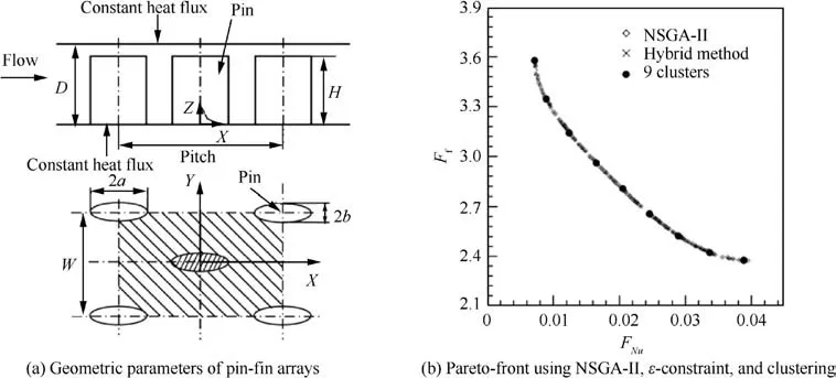
Fig. 24 Calculation domain and geometric parameters of pin-fin arrays.114

Fig.25 Schematic configuration of novel fan-shaped pin fin and comparisons of heat transfer performance for tradition circular pin-fin,novel fan-shaped and optimized fan-shaped pin-fins.117

Fig. 26 Comparisons of flow velocity vector, pressure drop and dimensionless Nusselt number of initial and optimized U-bend channels.119
Verstraete et al.carried out a series of optimization works on a U-bend cooling channel to minimize the pressure losses. In Refs. 120,121, the inner and outer curves of the Ubend channel were, respectively, parameterized by using four Bezier curves. Specifically, the 180° turn was composed of two Bezier curves,while the curves connecting the U-bend inlet and outlet were defined as a single Bezier curve.Four points in each Bezier curve were employed to control the shape of the curve. In these two works, the metamodel-assisted DE algorithm, was applied to reduce the pressure losses of the Ubend channel in Ref. 120 and not only reduce pressure loss but increase heat transfer of the U-bend channel in Ref. 121.
Willeke and Verstraetecarried out optimization on the same configuration as in Ref. 120,121, but different optimization methods were adopted to reduce the total pressure of the channel. They first established a continuous adjoint optimization framework as an attempt at the von Karman Institute for Fluid Dynamics. The steepest-descent method was applied to find the optimal geometry of the U-bend channel.In addition,two shape modification methods were investigated and compared to deform the inner and outer curves of the channel geometry. It was found that because the reduction of the design freedom, the Bezier-based method provided lower performance improvement compared with the method which presented the direct displacement of boundary grid points.Finally, the optimal geometry achieved a 46% reduction of total pressure loss compared with reference case.
In Ref. 123, a new parameterization method, which uses a tri-variate B-spline volume, was introduced to parameterize the U-bend channel for optimization.There were three advantages of the novel parameterization method,which provided a rich shape variation, a rapid and high-quality grid generation and had the ability for shape expressions in Computer Aided Design (CAD) systems. Therefore, in this optimization work,the tri-variate B-Spline volume method was used to deform the U-bend channel with 540 control points as shown in Fig.27(a)and generate the mesh.Then an adjoint approach was adopted to evaluate the sensitivities of the objective function. Finally, the optimal U-bend shape as shown in Fig. 27(b)was available in CAD format, which made it easier for manufacturing. The results proved that the novel parameterization method proposed in this work was cheap and robust for the gird generation process and it helped to remove two major bottlenecks in constructing high-fidelity shape optimization process.
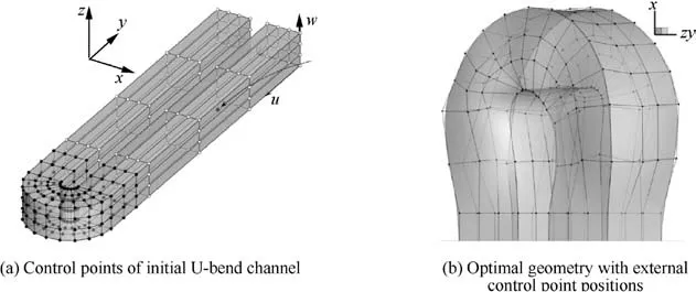
Fig. 27 Schematic of control points of initial and optimal U-bend channel.123
A discrete adjoint method together with a gradient-based optimizer was adopted by He et al.to optimize the Ubend channel with and without ribs embedded. The U-bend geometry and mesh were parameterized by utilizing the Free-Form Deformation (FFD) approach. For the rib-free Ubend channel, 113 control points were selected as design variables to provide enough freedom for the U-bend geometry modification.Among these,63 FFD points were free to move.As for the ribbed case, 146 design variables were chosen and 108 FFD points were used to deform the rib shapes while the U-bend channel geometry was kept unchanged. In this work, the heat transfer and aerodynamics were both considered as optimization objectives by defining a weighting function. The results showed that if one wanted to improve the overall heat transfer, the optimization of the U-bend shape is recommended,while if the focus is on improving the local heat transfer, the optimization of rib arrangements is more effective.Besides,it was demonstrated that the optimization framework proposed in this work could be used in many optimization areas.
To summarize the above optimization works, Table 3 presents the optimization information involved in the above references, including optimization objects, objective functions,design of experiments methods and optimization methods.
3.6.Optimizations of internal cooling systems of turbine vanes or blades
After reviewing many optimization works of internal cooling structures, like jet impingement cooling, rib turbulators, dimples and pin-fin arrays,and U-bend cooling channel,it is obvious that there are many optimization works carried out with focus on optimizing the internal cooling systems of turbine blades or vanes.
Dennis et al.performed a constrained optimization work on a large number of coolant passages located close to the turbine blade surface. Locations and discrete radii of circular cross-section coolant passages were selected as design variables to minimize the integrated surface heat flux penetrating the airfoil.Two constraints were set including the maximum temperature and minimum distance. A constrained optimization algorithm (IOSO) and a Parallel Genetic Algorithm (PGA)were employed to solve this problem. In addition, theyutilized the same optimization methods to optimize the 3-D serpentine cooling passage in turbine blades. Fig. 28(a)gives an example of the internally cooled blade. The optimization objective of this work was to make the stresses throughout the blade as uniform as possible. Results of both studies showed that the IOSO method was more robust and efficient than the PGA method. Comparisons of passage shape and temperature contours for initial and IOSO optimized designs are shown in Fig. 28.
It should be noticed that works related to the serpentine cooling passage are quite limited, although serpentine cooling passage have enlarged heat transfer areas and been adopted in real turbine blades. The main reason is that the serpentine cooling passage is too complicated. Thus,researchers adopted simplified shapes such as the single straight channel of a U-bend channel to study the internal cooling performance. To further improve the internal cooling performance, focus should be put on the serpentine cooling passage.
A series of optimization workswere carried out on an original C3X vane with 10 circular cooling passages. Nowak and Wro´blewskifirstly adopted a Single-Objective Genetic Algorithm (SOGA) to optimize the locations and diameters of 10 circular cooling passages within the vane.The objective of this optimization work was to minimize the stresses and material temperature of the vane. Finite Element Method(FEM)based software was utilized to predict the heat transfer within the component. Later,similar optimization work was developed by adopting the multi-objective evolutionary algorithm coupled with the Reduced CHT (RCHT)approach. Fig. 29,compares the temperature distributions for the initial design, selected RCHT optimized solution and selected EF based optimization. The results show that better designs can be obtained by taking the temperature and the thermal gradient within the solid into consideration.
Nowak et al.also used a multi-objective evolutionary algorithm with the Pareto method to optimize the shapes and locations of four and five non-circular cooling passages within a C3X blade.The optimization purposes were to reduce the thermal stress and the maximum temperature of the blade.To model each non-circular cooling passage, Bezier curves with four Bezier segments were used. In addition, to match the passage shape to the local geometry of the blade, a new technique called‘‘shape copy”was developed for two opposite Bezier segments extending along the profile. It was found that the optimal design reduced the solid temperature as much as 50 K with an almost 25%fall in thermal stress simultaneously.Inspired by this work, Mazaheri et al.did the same multiobjective optimization work but utilized different optimization methods, namely, the DE algorithm coupled with a reduced CHT approach. The reduced CHT approach means that the external flow around the blade is not solved and the convective heat transfer coefficient distribution found by experiment is imposed on the blade surface. It was demonstrated that by using this approach, the computational time is reduced.
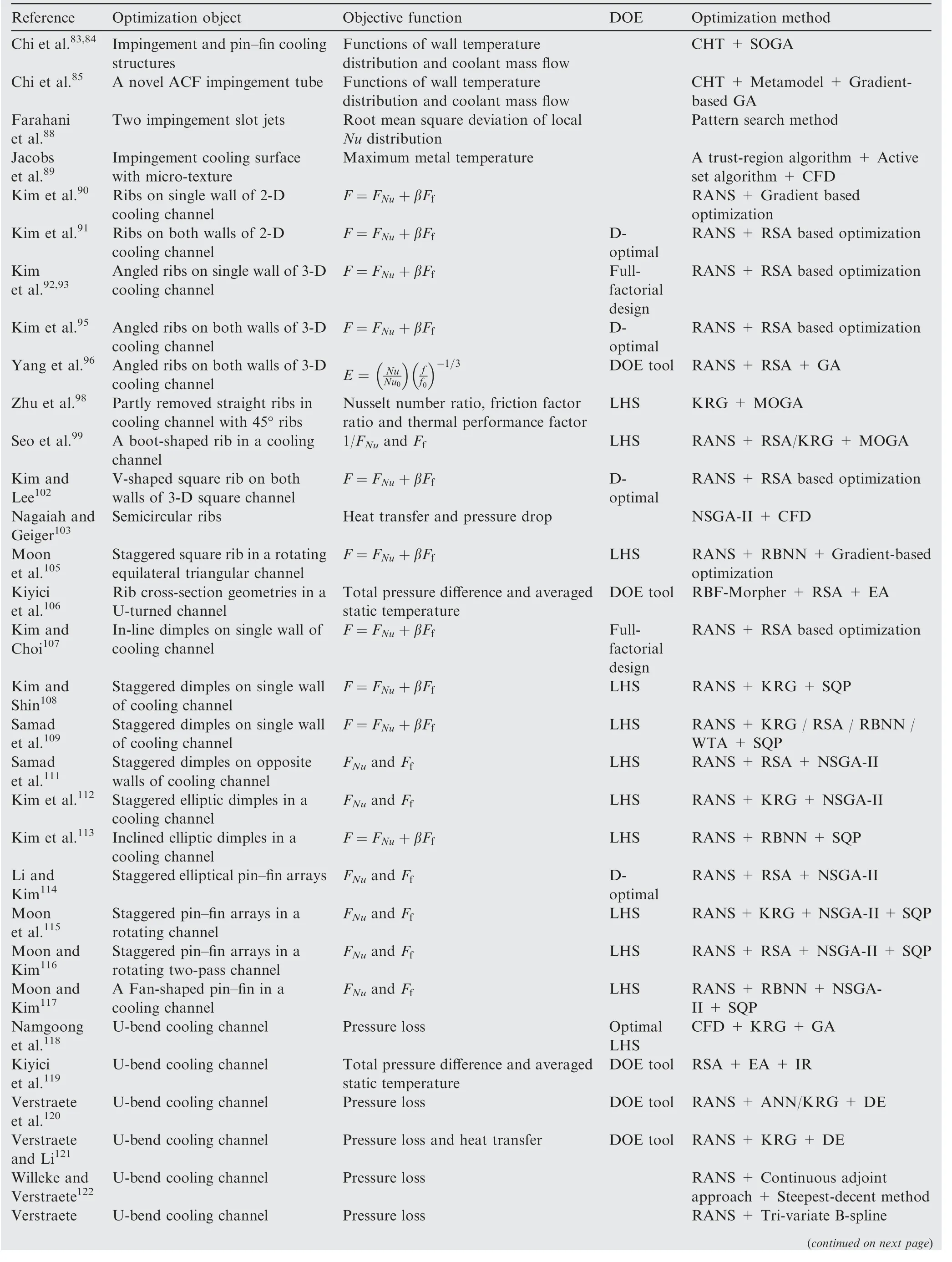
Table 3 Information of optimization of internal cooling structures.

Table 3 (continued)
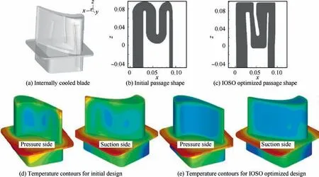
Fig. 28 An example of internally cooled blade and comparisons of passage shapes and temperature contours for initial and IOSO optimized designs.127
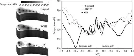
Fig. 29 Temperature distributions for initial design, selected RCHT optimized solution and selected EF based optimization.130
Based on the Nowak’s investigation, and considering the prohibitive computational demand of optimizing 3-D models,Wang et al.carried out an optimization work on a 2-D cross-section of the C3X blade to optimize the shapes, locations, and dimensions of the internal cooling passages. A Globally Convergent Method of Moving Asymptotes(GCMMA) algorithm was utilized to solve this problem. In addition,full CHT analyses were performed to obtain the temperature distribution of 3-D models extruded from 2-D crosssections. Results showed that the thermomechanical performances of turbine vanes were improved through the optimization of the cooling passages. The GCMMA method was also adopted by Xie et al.to optimize the sizes, distributions and shape of the cooling passages within the C3X blade.Both 10 cylindrical cooling passages and 4 non-cylindrical cooling passages shaped by Bezier curves were considered as the optimization objects to reduce the spatially averaged temperature and thermal stress of the blade. Fig. 30,presents comparisons of temperature and stress contours of the blade with 10 cylindrical original and optimized cooling passage distributions.It is found that the average temperature is reduced without increasing the thermal stress of the optimized design.
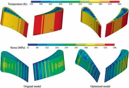
Fig. 30 Comparisons of temperature and stress contours for original and optimized models.134
As the CHT method can predict the temperature in each node of the solid mesh, allowing a straight forward computation of the thermal stresses,the CHT method is widely used in optimization of system with both solid and fluid. Verstraete et al.described the CHT method and its application to predict the performance and lifetime of an HPT blade operating at a very high inlet temperature. Then, theyemployed the CHT method as an analysis tool coupled with GA and two metamodels for aerothermal optimization of the first stage rotor blade of an axial HPT.The goal of this work was to maximize the lifetime of the turbine blade with limited cooling mass flow by varying the geometry and position of the cooling channels within the blade. Results showed that the geometry and position of the cooling channels had a significant effect on the lifetime of the blade and the optimal design of cooling channels led to an increase of the lifetime.
Inspired by these works,Nowak et al.adopted the CHT method for blade cooling system optimization of a supercritical stream turbine. The shape and location of the cooling passages were the design variables. In addition, the shape of each passage was modeled with a set of four Bezier curves. As in Ref. 131, the multi-objective evolutionary algorithm was used as the search approach.
Chi et al.performed an automatic optimization with GA and CHT analysis on ribbed cooling channel in a turbine rotor blade.Simultaneously,DOE analysis was used to find the optimal design of rib arrangement with the lowest average temperature and an optimum coolant amount in a rectangular channel.It was found that the optimal rib parameters obtained by the DOE analysis and GA search were quite similar.Therefore, the feasibility of design optimization with GA and CHT simulations was validated for the blade cooling structure. The superiority of the optimized schemes can be observed clearly from the temperature distribution on the blade surface as shown in Fig. 31.
Yu et al.adopted a surrogate model based on Two Loops Dynamic Optimization System (TLDOS) with RANS analysis to optimize the rib positions of the cooling passage in a turbine blade to augment the heat transfer and aerodynamic. It was found that significantly improvement of the blade performance was achieved through optimization. Moreover, the optimization method based on the surrogate model was demonstrated to be proper and effective for 3-D internal cooling design of turbine blade.
From the above description it is obvious that the CHT method has been popular to optimize the internal cooling systems in turbine blades and vanes. Besides, to reduce the computational efforts during the optimization process, surrogate models were usually adopted and coupled with the CHT method. Furthermore, evolutionary algorithms were the most widely used search methods for this kind of optimization problem.
4. Conclusions and future perspectives
The turbine is the most important component of a gas turbine engine,and its performance has critical influences on the overall performance of the engine. The thermal efficiency and output power are the key indices to evaluate the performance of a gas turbine. In detail, the increase of thermal efficiency can be realized by increasing the inlet temperature of the turbine,which is far higher than the melting temperature of the blade material.Due to this fact,better cooling structures with higher cooling performances need to be further developed and designed to protect the blade from the hot gas. Optimization of the turbine cooling structures has become an effective way to achieve better structures with higher cooling performance and has attracted much attention in the past decades.To summarize the research status and give further perspectives, this paper reviews the optimization works on cooling structures in gas turbines. The main conclusions are drawn as follows.

Fig. 31 Temperature distributions on blade surface for different schemes.138
(1) Different film hole shapes including cylindrical hole,fan-shape hole, double-jet hole, round-to-slot hole, and other hole shapes were optimized on flat plates. Fanshaped holes were the most widely studied hole shapes.RANS analysis coupled with different surrogate models and searching methods was most commonly applied in flat plate film cooling. In detail, SQP and GA were usually adopted for single-objective optimizations while NSGA-II was used for multi-objective optimizations.
(2) In contrast to the film cooling optimizations conducted on the flat plate, optimization of the film cooling holes on turbine blades or vanes focused not only on hole shapes’parameters,but also on the hole to hole spacing or arrangements of hole arrays. In terms of the optimization objectives, most of investigations considered both the film cooling effectiveness and aerodynamic loss.In addition, CFD calculations together with singlefidelity surrogate models and EA were commonly utilized to solve these optimization problems.It was found that there were few studies considering CHT analysis and multi-fidelity surrogate models in this field.
(3) Optimizations of internal cooling were carried out in many aspects, including impingement cooling, rib and dimple structures in the serpentine cooling channel,pin-fin arrays on the trailing edge, shapes of U-bend channel, and internal cooling passages in turbine vane or blade.As for the optimizations of impingement cooling and internal cooling passage conducted on turbine vane or blade, CHT analysis was usually performed to obtain the temperature field and flow field of the blade.While for the optimizations of ribs, dimples, pin-fin arrays and shapes of U-bend channel, similar optimization methods as those adopted in the flat plate film cooling was utilized.
(4) Although many film cooling optimization studies have been conducted on flat plates and blades or vanes, few of them have taking the CHT into consideration due to its complexity and heavy computational demand.Besides, optimizations of the cooling passages in the blades mainly focused on straight passages. The investigations of serpentine passages optimizations and optimizations of cooling passage considering the ribs or dimples were limited.Moreover,it was found that single fidelity surrogate models like RSA,RBF,RBNN,ANN,KRG and WTA were widely used in the existing literatures.To ensure the accuracy of surrogate models,many high-fidelity sampling points were needed. This procedure was time consuming due to the heavy calculations.Therefore, based on the above discussion,the future works can be carried out from following aspects:
(1) In order to make the research work closer to the realistic situation, the optimization of film cooling should consider the CHT effects. In addition, the optimization of the serpentine passages with heat transfer enhancement structures should be paid more attention.
(2) Multi-fidelity surrogate models can reduce the calculation demands while maintaining the accuracy by combining both the high-fidelity and easy-obtained lowfidelity sampling points. Thus, multi-fidelity models can be considered and adopted to replace the singlefidelity surrogate models in some optimization problems.
(3) The turbine blades are subjected to the comprehensive effects of high temperature and pressure, centrifugal load, vibration load, thermal stress, gas corrosion and high temperature oxidation during the working process.These effects can be classified into three aspects, i.e.,high working temperature, complex working stresses and high corrosive environment. However, many optimizations of blade cooling structures were only aimed at improving the cooling efficiency without considering the influences of variation of cooling structures on thermal stress and strength of the blade materials. Therefore,multi-disciplinaryandmulti-objective optimizations should be widely investigated.
(4) Although optimization has been an effective path to achieve better structures with higher cooling performance, many optimized structures still cannot be adopted in the engineering applications due to the limitation of manufacturing techniques. Therefore, manufacturing techniques should be further developed and considered in the optimization process.
The authors declare that they have no known competing financial interests or personal relationships that could have appeared to influence the work reported in this paper.
This work was supported by the National Natural Science Foundation of China (No. 51676163), by the National 111 Project, China (No. B18041), and by the Guangdong Basic and Applied Basic Research Foundation, China (No.2019A1515111146).
