Understanding the Coffee ring Effect on Self-discharge Behavior of Printed micro-Supercapacitors
Jingzhi Hu ,Zhaohua Xu,Kai Yuan,Chao Shen,Keyu Xie*,and Bingqing Wei*
Printed micro-supercapacitor exhibits its flexibility in geometry design and integration,showing unprecedented potential in powering the internet of things and portable devices.However,the printing process brings undesired processing defects(e.g.,coffee ring effect),resulting in severe self-discharge of the printed micro-supercapacitors.The impact of such problems on device performance is poorly understood,limiting further development of microsupercapacitors.Herein,by analyzing the self-discharge behavior of fully printed micro-supercapacitors,the severe self-discharge problem is accelerated by the ohmic leakage caused by the coffee ring effect on an ultrathin polymer electrolyte.Based on this understanding,the coffee ring effect was successfully eradicated by introducing graphene oxide in the polymer electrolyte,achieving a decline of 99% in the self-discharge rate.Moreover,the micro-supercapacitors with uniformly printed polymer electrolyte present 7.64 F cm-3volumetric capacitance(14.37 mF cm-2areal capacitance),exhibiting about 50% increase compared to the one without graphene oxide addition.This work provides a new insight to understand the relationship between processing defects and device performance,which will help improve the performance and promote the application of printed micro-supercapacitors.
Keywords
coffee ring effect,hybrid printing,micro-supercapacitor,polymer electrolyte,self-discharge
1.Introduction
With the fast-growing wearable devices and internet of things,[1,2]it is highly desired to integrate more powerful energy storage devices with miniaturized sizes into entire device systems.[3,4]Owing to their advantages in power density,long cycle life,and safe operation,micro-supercapacitors(MSCs)have been considered as one of the most promising candidates,which can be solely or combined with micro-batteries to power portable microelectronics or be compatible with micro-energy harvesting systems.[5,6]However,the requirement of μm-level feature size and easy integration makes it necessary to apply advanced fabrication methods.[7,8]Printing technology,which has excellent process flexibility and geometry controllability,is an emerging technology in MSC fabricating.[9,10]Up to now,impressive progress of manufacturing MSCs with complex structures and specific applications has been achieved via printing.[11-14]However,the introduction of new fabrication methods brings unconventional problems(e.g.,the coffee ring effect),and the influence of processing defects on device performance is poorly understood.
The coffee ring effect is a common phenomenon during printing.[15,16]Due to the solvent’s non-uniform evaporation rate at the center and the verge and the pinned contact line’s formation,the solute in the droplet will migrate from the center to the verge,resulting in the ring-like deposition.[17]While for MSCs,these non-uniform defects will occur in both electrodes and polymer electrolytes.[18]Compared to electrodes,the coffee ring effect in polymer electrolytes is often neglected.This is because the small inhomogeneity of morphology(thickness variation within 5-10 μm)has little impact on thick polymer electrolyte films(over 100 μm via casting).[19,20]However,the inhomogeneity induced by the coffee ring effect will cause severe problems in device assembly and performance when it is comparable to the thickness of ultrathin polymer electrolyte films(≤10 μm)in the development of flexible and three dimensional MSCs.[21,22]
To understand the coffee ring effect on MSCs,herein,we fabricated carbon nanotube(CNT)-based MSCs with sandwich configuration via hybrid printing.The coffee ring effect was observed in the printed poly(vinyl alcohol)(PVA)-based polymer electrolytes.Compared to the MSC with a thicker PVA polymer electrolyte film(~30 μm),the MSC with a thinner one(~10 μm)exhibits better volumetric capacitance but suffers from severe self-discharge induced by ohmic leakage.This phenomenon was due to the uneven polymer electrolyte caused by the coffee ring effect.The thinnest thickness is close to the CNT diffuse depth that has been verified by Raman line scanning,leading to low leakage resistance and fast self-discharge behavior.To tackle the severe self-discharge issue,graphene oxide(GO)nanosheets were added to the polymer electrolyte to suppress the coffee ring effect.The resultant MSC shows a decline of 99% in the self-discharge rate and presents better electrochemical performance,achieving high volumetric capacitance(7.64 F cm-3at 0.1 A cm-3for a full device)and good rate ability(68% retention from 0.1 to 2 A cm-3).
2.Results and Discussion
2.1.Fabrication and characterization of MSCs
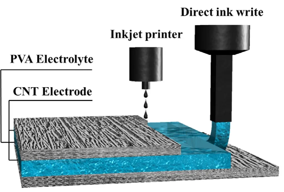
The schematic of the MSC printing process is shown in Figure 1.A hybrid printing strategy was applied based on ink rheology to obtain the devices with ultrathin polymer electrolytes.Inkjet printing was used to print the CNT-based electrode ink for its advantages in controlling thickness.At the same time,the PVA-based polymer electrolyte has to be printed by direct ink writing technology due to its high viscosity.Firstly,a uniform CNT electrode film with a thickness of about 4-5 μm was printed on a glass substrate by repeating the printing process(Figure S1).The PVA polymer electrolyte was then directly written on the printed electrode,followed by evaporation to get the 10 μm thick polymer electrolyte film.After the film formation,another CNT electrode was printed onto it,fabricating the whole MSC device without any post-processing(named PVA-10).For comparison,another MSC with a 30 μm thick polymer electrolyte film was also fabricated(PVA-30).

Figure 1.Schematic diagram of the fabrication process of a fully printed micro-supercapacitor.
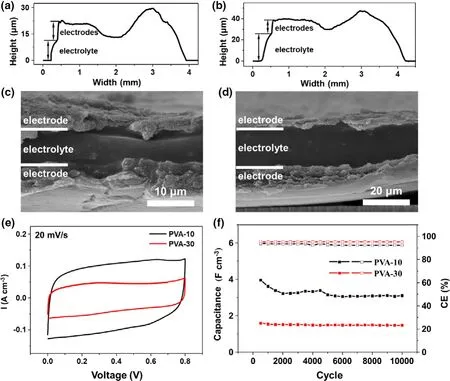
Step profiler and scanning electron microscopy(SEM)were used to measure the polymer electrolyte’s thickness of the MSCs.Figure 2a,b are the height profiles of PVA-10 and PVA-30,respectively,and the electrode and electrolyte parts are each labeled for easier distinguish.For the PVA-10 MSC,the whole device is about 20 μm thick on average with about 10 μm electrodes and 10 μm electrolyte.In contrast,for the PVA-30 MSC,the entire device exhibits an average thickness of 40 μm with 10 μm electrodes and 30 μm electrolyte.Both have about 8 μm sunken in the middle of the devices due to the coffee ring effect when the PVA films are forming.The sandwich structures are clear from the cross-sectional images,as shown in Figure 2c and d,in which the thicknesses of the two MSCs are in accord with the height profiles.The electrochemical performance of the two MSCs is presented in Figure 2e,f,and Figure S2,S3.Both MSCs display near rectangle shape for the cyclic voltammetry(CV)test at 20 mV s-1,and PVA-10 shows nearly twice volumetric current density compared to PVA-30,simply due to the reduction of the thickness.The cycle performance concludes the same results;after 10 000 cycles,the PVA-10 MSC still presents 3.11 F cm-3volumetric capacitance,nearly double the value of the PVA-30 MSC(1.48 F cm-3).

Figure 2.Height profiles of MSCs with a)PVA-10 and b)PVA-30 polymer electrolytes.The cross-section SEM photographs of MSCs with c)PVA-10 and d)PVA-30 polymer electrolytes.e)The cyclic voltammetry(at 20 mV s-1)and f)cycle performance(at 1 A cm-3)of MSCs with PVA-10 and PVA-30 polymer electrolytes.
2.2.Self-discharge analysis of ultrathin MSCs
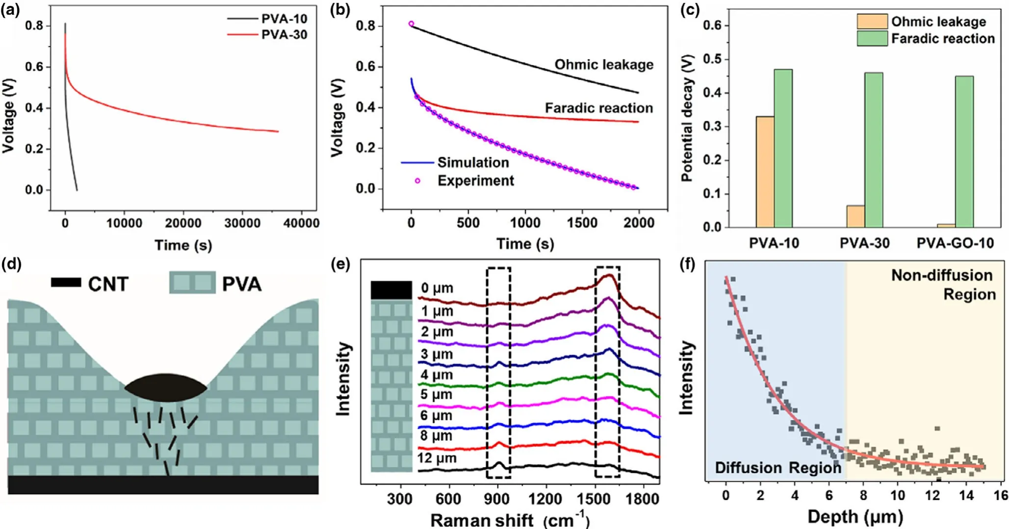
The self-discharge curves with different thicknesses of polymer electrolytes are given in Figure 3a.The PVA-10 device shows a swift selfdischarge process;the voltage drops from 0.8 to 0 V only after 2000 s,while the PVA-30 device maintains more than one-third of the initial voltage even after 36 000 s.Typically,the supercapacitor’s self-discharge phenomenon is mainly caused by three mechanisms:ohmic leakage,faradic reaction,and charge redistribution.[23]The ohmic leakage refers to the leakage resistance between the electrodes,which is similar to the dielectric capacitor.Under this mechanism,the relationship between the voltage of MSC U and the self-discharge time t can be expressed as

Figure 3.a)The self-discharge performance of MSCs with PVA-10 and PVA-30 polymer electrolytes.b)The fitted curve of self-discharge of MSC with PVA-10 polymer electrolyte.c)The potential decay of two self-discharge mechanisms in MSCs with different polymer electrolytes.d)The illustration of the coffee ring relates to self-discharge problems.e)The Raman line scans of the cross-section of a micro-supercapacitor at different depths.f)Raman intensity of the g-band as a function of MSC’s cross-section depth from the upper CNT electrode.

where U0is the origin voltage of MSC,and RC is the time constant of the MSC self-discharge process.
The faradic reaction indicates the redox reaction of impurities or functional groups at the electrode surface due to the overpotential;it is controlled by activation as

where a,b,and c are the constants and i0is the exchange current.
Unlike the above two mechanisms,charge redistribution refers to the inequality charging state between the electrode surface and bulk.It is mainly controlled by diffusion and can be expressed as where m is the diffusion parameter and denotes the diffusion rates of ions near the electrode surface.

Combined the above self-discharge mechanisms,one can get[24]

Based on Equation(4),one can fit a self-discharge curve,and the results are shown in Figure 3b and Figure S4.The contributions of ohmic leakage and faradic reaction in each device are presented in Figure 3c(the PVA-GO-10 MSC is shown in Section 2.3).It can be noticed that activation controlled faradic reaction exists in all MSCs with similar potential decay due to the self-discharge process caused by functional groups(i.e.,-OH)attached to the electrodes.[25]However,ohmic leakage is the main reason for the different self-discharge behaviors of the three MSCs.As ohmic leakage is often related to incomplete sealing of electrodes or inter-electrode contacts,it is speculated that this phenomenon might be caused by two reasons.[26]On the one hand,the coffee ring effect will result in a considerable nonuniformity of the polymer electrolyte.The limited mechanical strength in the ultrathin region will bring ohmic leakage passage.[22]On the other hand,as illustrated in Figure 3d,when printing the second electrode layer on top of the uneven electrolyte film,the CNT ink prefers to be absorbed by the concave portion of the polymer electrolyte and diffuses into it.When the diffuse distance is comparable to the polymer electrolyte’s thickness,it will lead to the ohmic leaking and fast self-discharge problem.
To verify this assumption,the cross-section of MSC was characterized via Raman line scanning to prove the CNT’s diffusion in the PVA electrolyte.Raman spectra at different depths of the polymer electrolyte are presented in Figure 3e.When the depth is 0 μm(i.e.,the interface between CNT electrode and PVA electrolyte,and was determined by the intensity of Raman peak of PVA, as shown in Figure S5), the g-band of carbon at about 1580 cm-1is very strong,indicating the existence of CNTs.It is gradually weakening and diminishing with the depth increase,while the Raman peak at about 914 cm-1,corresponding to the twist of CH2in PVA,is increasing.[27]Figure 3f shows the relationship between the g-band intensity and depth in polymer electrolyte.All these experimental data are well fitted by the exponential function,which is consistent with Fick’s first laws(the fitted parameter can be seen in Table S1).The diffusion depth is very similar to the thinner portion of the electrolyte film,leading to severe ohmic leakage-induced self-discharge of the PVA-10 MSC.For PVA-30 MSC,though considering the coffee ring effect,the CNT diffusion length is still far less than the polymer electrolyte’s thickness,preventing severe self-discharge behavior from ohmic leakage.To control CNT diffusion depth,one can play with the PVA concentration.[28]For 6 wt% and 10 wt% PVA,the diffusion depth is about 10 and 3 μm,respectively(Figure S6).However,the increase of PVA concentration cannot solve the coffee ring effect problems and would make it more challenging to precisely control electrolyte film’s thickness.
2.3.Slowing self-discharge via eliminating the coffee ring effect
To solve the ohmic leakage problem without increasing the thickness of polymer electrolytes,graphene oxide(GO)is introduced into the polymer electrolyte to form the 10 μm thick PVA-GO-H3PO4electrolyte(named PVA-GO-10).The size distribution of GO is 26.5 ± 14.8 μm(Figure S7),and Raman,FTIR,and SEM were used to ensure the addition of GO with different concentrations(Figure S8).It is found that the GO introduction can effectively suppress the coffee ring effect.When GO concentration reaches 2 mg mL-1or more,the coffee ring effect is effectively controlled,as shown in Figure 4a-d and Figure S9.Thus,we choose the PVA-H3PO4polymer electrolyte with 2 mg mL-1GO addition in the following experiment.Compared to the PVA-10 polymer electrolyte,the height profile and the two dimensional morphology of the PVAGO-10 polymer electrolyte present a relatively flat film.The weakening of the coffee ring effect can be well explained as the competition between deposition and evaporation(Figure S10).[29]For a solution,when the solute deposition is faster than the droplet evaporation,the deposited solute will pin the contact line and form the coffee ring.Otherwise,the solute does not have enough time to pin the contact line,thus suppressing a coffee ring formation.[30]In the PVA-GOH3PO4electrolyte,the introduction of μm size GO will bind with PVA chains via hydrogen bonding (Figure S8b).[31,32]According to the competition model,the significant increase of solute size by GO addition will hinder its accumulation at the contact line,leading to the uniform deposition with increasing GO concentration.[33]

Figure 4.a,b)Height profiles of PVA-10 and PVA-GO-10 polymer electrolyte,respectively.c,d)The 2D morphology of PVA-10 and PVA-GO-10 polymer electrolyte,respectively.e)The fitted self-discharge curve of MSC with PVA-GO-10 polymer electrolyte.f)The illustration of the GO effect in PVA-GO-10 based microsupercapacitor.
Upon eliminating the coffee ring effect in polymer electrolyte,PVA-GO-10 MSC was fabricated and evaluated(the height profile and the cross-sectional SEM are shown in Figure S11).Figure 4e shows the experimental and fitted self-discharge results of PVA-GO-10 MSC.Compared to PVA-10 MSC and PVA-30 MSC(Figure 3c),the PVA-GO-10 MSC exhibits the least ohmic leakage,and after more than 36 000 s,nearly half of the original voltage remains.The leakage current held at 0.8 V with an about tenfold difference can confirm this phenomenon(Figure S12).Moreover,the reciprocal of self-discharge time for half voltage decay was calculated to quantify the self-discharge rate.The decline of 99% and 20% is achieved in PVA-GO-10 compared to PVA-10 and PVA-30,respectively.The result can be schematically explained in Figure 4f.It can be concluded that the GO introduction suppresses the coffee ring effect,and a uniform electrolyte film with 10 μm thick is enough to prevent the CNT penetration.Moreover,the π-stacking interaction between CNT and GO(verified by UV-vis in Figure S13)may reduce the diffuse coefficient of CNT,[34]resulting in slowing self-discharge of the fully printed ultrathin MSC.
2.4.Electrochemical performance of the ultrathin MSC with PVA-GO electrolyte
The electrochemical performances of the PVA-GO-10 MSC were researched,including CV tests from 5 mV s-1to 100 mV s-1and galvanostatic charge-discharge(GCD)tests from 0.1 A cm-3to 2 A cm-3with a voltage window from 0 to 0.8 V(Figure S14).Compared to the PVA-10 MSC,the PVA-GO-10 MSC shows a longer charge-discharge time,indicating a higher electrochemical capacitance(Figure 5a).Additionally,the CV rate ability was also tested and compared from 0.1 to 2 A cm-3(Figure 5b).With the current density increase,PVA-10 MSC shows 4.92 F cm-3volumetric capacitance at 0.1 A cm-3and 3.01 F cm-3at 2 A cm-3,about 61% retention.For PVA-GO-10 MSC,the volumetric capacitance is decreased from 7.64 F cm-3(0.1 A cm-3)to 5.19 F cm-3(2 A cm-3),about 68% retention.Besides,both MSCs’cyclic stability has been tested at 1 A cm-3up to 10 000 cycles.The PVA-10 MSC presents 3.11 F cm-3volumetric capacitance and 92% coulombic efficiency,while the PVA-GO-10 MSC exhibits 4.23 F cm-3volumetric capacitance and 96% coulombic efficiency. The better electrochemical performance of PVA-GO-10 MSC is due to improved ion conduction and lower resistance(Figure S15),which come from the GO induced low degree of crystallization and additional ion conduction channels.[32,35]

Figure 5.a)The galvanostatic charge-discharge(at 0.1 A cm-3)curves,b)CV rate performance,and c)cycle stability performance(at 1 A cm-3)of MSCs with PVA-10 and PVA-GO-10 polymer electrolytes.
3.Conclusion
In summary,MSCs with different thicknesses of PVA polymer electrolyte were fully printed,and their self-discharge behaviors were analyzed.Compared to the PVA-30 MSC,PVA-10 MSC exhibits severe ohmic leakage problem due to the coffee ring effect in an ultrathin polymer electrolyte.GO was added into PVA electrolytes to suppress the coffee ring effect successfully.The ohmic leakage in PVA-GO-10 MSC is eliminated and results in a decline of 99% in the self-discharge rate compared to PVA-10 MSC.Besides,the GO addition also improves the electrochemical performance of PVA-GO-10 MSC,a higher volumetric capacitance(7.64 F cm-3vs 4.92 F cm-3at 0.1 A cm-3)and better rate ability(68% vs 61% retention from 0.1 A cm-3to 2 A cm-3)compared to PVA-10 MSC.These findings provide a new perspective to reveal the influence of processing defect on the device performance,facilitating micro-supercapacitor fabrication and application development
4.Experimental Section
Ink preparation:The CNT ink was prepared by applying the typical dopamine coating method.[36]80 mg carboxyl-modified multiwalled CNTs(MWCNTs,diameter<8 nm,XFNANO)and 8 mg dopamine hydrochloride(Aladdin)were added into the Tris-HCl buffer solution(pH=8.5,40 mL).Then,the mixture was further dispersed by vigorous agitation for 24 h,followed by 8000 rpm centrifugation for 10 min with water and alcohol,respectively.The PDA-modified CNT powder was got by evaporating at 80°C for 12 h.Finally,1 mg mL-1PDA-modified CNT was added into deionized water and ultrasonicated for 2 h to get the stable CNT ink.
The PVA-GO-H3PO4polymer electrolyte inks were prepared following a literature report.[37]1.6 g PVA(PVA-124,Sinopharm Chemical Reagent),0,20,40,and 60 mg GO(made by improved Hummer’s method[38]),and 2 g H3PO4(≥85% ,Sinopharm Chemical Reagent)were added into 20 mL deionized water with vigorous stirring and ultrasonication.Then,the mixtures were headed at 90°C for 2 h with stirring to obtain the solution.
Fabrication of MSCs:The printing process was the combination of inkjet printing and direct ink writing on a 3-axis positioning stage(Xi’an Particle Cloud Biotechnology,PCPrinter NM150),whose motion can be controlled by programming.To fabricate a micro-supercapacitor,the PDA@CNT ink was first printed on glass by an inkjet printer(nozzle diameter is 50 μm),with 50°C heating to avoid ink gathering.The PVA-GO-H3PO4solution was then written through a micro-extruder(260 μm in diameter)to get the polymer electrolyte film on the electrode at ambient temperature.After evaporation of the polymer electrolyte solution,another CNT electrode film was printed on the electrolyte film to fabricate the full device.
Characterizations:The line and map thicknesses of the devices were characterized by a step profiler(Bruker DaktekXT).The cross-sectional morphologies of the devices were characterized by scanning electron microscope(FEI nova nanosem 450).The Raman spectra with line scanning were carried out on the crosssection of micro-supercapacitor with 0.1 μm step for 16 μm by a confocal Raman microscope(Renishaw inVia)using a 532 nm laser under ambient conditions.The functional groups of PVA-H3PO4polymer electrolytes with different GO concentrations were characterized by FTIR spectroscopy(Thermo Nicolet iS50 FT-IR).The size distribution of graphene oxide nanosheets was tested by laser particle sizer(OMEC Topsizer).
All electrochemical characterizations were carried out at room temperature with an electrochemical workstation system(Solarton 1470E)in a two-electrode configuration.Galvanostatic charge-discharge curves were measured from 0.1 to 2 A cm-3for one device in the voltage range of 0-0.8 V.Cyclic voltammetry data were obtained with a scan rate from 5 to 100 mV s-1.The self-discharge curve was tested by charging to 0.8 V,holding for 1800 s,and taking open-circuit voltage for 36 000 s.The cycle life was tested at a current density of 1 A cm-3for 10 000 cycles.
Acknowledgements
The authors acknowledge the financial support of this work by the Science,Technology,and Innovation Commission of Shenzhen Municipality(Program No.JCYJ20180508151856806,No.JCYJ20180306171355233),and the Innovation Foundation for Doctor Dissertation of Northwestern Polytechnical University(Program No.CX201944)
Conflict of Interest
The authors declare no competing interests.
Supporting Information
Supporting Information is available from the Wiley Online Library or from the author.
 Energy & Environmental Materials2022年1期
- Energy & Environmental Materials的其它文章
- Classifying Electrolyte Solutions by Comparing Charge and Mass Transport
- Two-dimensional Boron Nitride for Electronics and Energy Applications
- Harnessing the Unique Features of 2D Materials toward Dendrite-free Metal Anodes
- Recent Development in Defects Engineered Photocatalysts:An Overview of the Experimental and Theoretical Strategies
- 2D/2D Heterostructures:Rational Design for Advanced Batteries and Electrocatalysis
- Promising Electrode and Electrolyte Materials for High-Energy-Density Thin-Film Lithium Batteries
