Effects of swirler position on flame response and combustion instabilities
Lingling XU, Jinyi ZHENG, Guoqing WANG, Lei LI,*, Fei QI
a School of Mechanical Engineering, Shanghai Jiao Tong University, Shanghai 210096, China
b King Abdullah University of Science and Technology, Thuwal, Saudi Arabia
KEYWORDS Intrinsic thermoacoustic instability;Lean premixed combustion;Mode switch;Swirl flame;Swirler position
Abstract This study is concerned with the experimental and theoretical investigation of the combustion instabilities in a premixed swirl combustor. It is focused on the effects of the swirl mixing distance on the intrinsic thermoacoustic mode. The swirler as an origin of the swirling flow is also the source of the flow disturbance,which has effects on the flame response.The location of the swirler is varied in the experiment to study the effect on combustion instabilities and flame transfer functions. A low order model is built to analyze the thermoacoustic instabilities of the combustion system.The experimental results show that the ITA switches from an unstable state to a stable state as the swirl mixing distance changes with an increment of 15 mm; while the instability of the quarter-wave mode is not varied. The measured Flame Transfer Functions (FTFs) show that the gain curves of the frequency-dependent FTFs seem to be stretched or compressed with the modulation of the swirler position, which has effects on frequencies and instabilities of thermoacoustic modes.With the low order model,the effects of flame response on combustion instabilities are analyzed and the flame dominant nature of the ITA mode is confirmed.
1. Introduction
Thermoacoustic instability of the lean premixed gas turbine combustion system remains one of the most important issues for industrial and academic communities.To solve the problem, the driving mechanisms of combustion instabilities must be deeply understood, the prediction tool should be developed and the control strategy needs to be prepared in the prototype development of a combustor.
Combustion instabilities are generally driven by two kinds of feedback loops. The first is the feedback between the flame and the acoustic modes of the combustor.This feedback loop forms the cavity thermoacoustic mode of the combustion system.It indicates that the cavity modes are always locked on the pure acoustic modes. The second mechanism is the coupling between the unsteady heat release rate and the pressure waves of a mode, which is no need to be consistent with the pure acoustic modes of the burner. This mode is termed as the Intrinsic Thermoacoustic modes(ITA).Both the thermoacoustic instabilities of cavity modes and ITA modes are driven by the coupling between the perturbation and the flame oscillation.The difference is that the ITA mode is driven by a local feedback loop and the cavity mode is driven by the global feedback loop.
The different feedback mechanisms of the two kinds of thermoacoustic modes mean that the control strategies of pressure fluctuations would also be different.For the cavity modes,despite the flame response and operation conditions,the mode frequencies are determined by the geometries of various sections in the combustor and so as the instabilities.For instance,the frequency of the Helmholtz mode of a combustor is typically associated with the volume of a plenum at the upstream of the flame;the frequencies of the quarter wave mode and also the three quarters mode and so on are determined by the length of the combustion chamber. Traditionally, dampers,e.g., the acoustic liner and Helmholtz resonator, are applied as an effective passive method to suppress combustion oscillations. It changes combustion instabilities in two ways. Firstly,dampers can absorb sound energy. As a result, the interaction between the unsteady flame and the acoustic field is weakened.Secondly, dampers modulate acoustical boundary and geometry of the combustor. Consequently, mode frequencies are changed.Then,flame responses are varied and thermoacoustic instabilities are subsequently modulated. However, dampers are not suitable for suppressing intrinsic thermoacoustic instabilities.Because the reduction of sound reflection caused by the damper can enhance the pressure fluctuation of the ITA mode.This is due to that as the global feedback of the cavity mode is weakened, the thermoacoustic system tends to be dominated by the local feedback mechanism.With theoretical,simulation and experimental methods, several studies have given conclusive evidence that the instability of the ITA mode can be strengthened by improve the acoustic loss at both upstream and downstream side of the flame. It gives the challenge of controlling intrinsic thermoacoustic instabilities. Ghani and Polifkerecently took a numerical study on controlling the ITA mode of a laminar slit flame by adding hydrogen to the total fuel flow. The control strategy is to shift the mode to higher frequencies to reduce the gain of the flame response.Because the velocity sensitive premixed flame acts as a typical low-pass filter for acoustic disturbances. In the present work,we intend to raise a point to control the intrinsic thermoacoustic instability in a swirl burner by modulating the position of the swirler. The position of the swirler is an important factor that may have effects on the flame response and the feedback loop between the flame and upstream velocity perturbation,which is not involved in Ghani’s work.
To deeply understand the feedback mechanims, firstly, it is necessary to discuss how perturbations affect combustion instabilities and how the flame responds to disturbances.Lieuwen et al.studied the driving mechanism of equivalence ratio φ oscillation in a lean premixed low emission gas turbine combustor.It was found that the coupling between the perturbation of the fuel supply rate and the heat release oscillation drives the pressure fluctuation in the combustor. The location of the fuel injector, which determines the time delay of the flame response,is a key factor for the φ-oscillation mechanism.Th φ-oscillation mechanism is a possible driving mechanism in partially premixed combustion when the fuel–air mixing process takes place inside the combustor. However, it is a secondary mechanism in a perfect premixed combustion system.Flame area fluctuation is an important driving mechanismin a fully premixed combustor. Palies et al.investigated the driving mechanism of flame response in a premixed swirl combustor. It was found that the fluctuation of flame surface area is mainly controlled by the azimuthal velocity perturbation and the axial velocity perturbation. The first is generated by the interaction between the acoustic waves and the swirler,in the forms of vorticity waves. This part of the disturbance is convected with the bulk flow and leads to the oscillation of the flame root angle.The axial velocity perturbation interacts with the outlet of the swirler nozzle and vortex rings are generated,which can roll up the flame.The two mechanisms have a combined effect on the flame response.
As the azimuthal velocity disturbance is generated at the swirler, the location of the swirler has a remarkable effect on the flame response. Komarek and Polifkestudied the effects of the position of the swirler on the flame response with experimental and numerical simulation methods. Results showed that the flame shape was insensitive to the location of the swirler; however, the flame response was significantly modulated.Kimtook an experimental investigation about the effects of the swirler location on combustion instabilities. It was found that changing the location of the swirler lead to remarkable variations of the flame response and the limit cycle of pressure oscillation. However, the analysis of the thermoacoustic modes was not shown in the paper. Albayrak et al.experimentally studied the Intrinsic Thermoacoustic (ITA)modes in a premixed swirl combustor. They proposed an extended criterion for predicting the frequency of ITA mode at two swirler positions.The frequency of ITA mode was analyzed using the time lags of the flame response,but the effect of interaction index on the instabilities was barely mentioned.The above researches provided valuable results to understand the effects of swirler position on flame response and combustion instabilities. However, due to different focuses of these studies,the phenomena and conclusions are different.Besides,the research on the effect of the swirler position on both the flame response and the instability of ITA mode is not enough in the experiment. And the comparison of instabilities of both the cavity thermoacoustic mode and the ITA mode when varying the swirl mixing distance is also rarely found in references.Furthermore, detailed modeling studies on these effects are still inadequate. In our previous work,the feature of the ITA mode had been investigated through a setup of a premixed swirl flame. In this study, both experimental and model methods are used to further investigate combustion instabilities and flame response with the variation of the swirler location from a fully premixed combustor. It will give direct evidence that both the gain and phase of the flame transfer function have crucial effects on thermoacoustic instabilities,particularly on that of the ITA mode. Then, the flame dominant nature of the ITA mode will be deeper understood.
In the following, the experimental system will be shown at first. Then, the corresponding results of self-excited combustion instabilities are introduced.Subsequently,the flame transfer functions, which represent the feature of the flame response, are measured at various swirl mixing distances.Finally,an acoustic network model is built to analyze the thermoacoustic instabilities of the combustion system.
2. Experimental setup
2.1. Combustor
The swirl combustor for studying the self-excited combustion instabilities is shown in Fig. 1.The combustor consists of a plenum with a 6-inch loudspeaker at the bottom,a mixing channel with a swirler, and a combustion chamber with an acoustical rigid wall. The fuel gas (methane) flow and the airflow are controlled by two mass flowmeters (Sevenstar CS200A, error:±1%) in separate pipes and then mixed in a single pipe before entering the plenum.Two perforated plates,with a thickness of 5 mm,are set in the plenum to homogenize the mixture flow.A bluff body and an axial swirler with a swirl number of about 0.6are located in the mixing passage with a diameter of 20 mm. The swirler has eight blades shaped with the NACA-8411 airfoil.As a part of the combustion chamber, an optical accessible quartz tube is installed at the base plate of the burner. Two pressure transducers are applied to capture the pressure oscillations (P’and P’) in the combustion chamber with the semi-infinite-tube method.The unsteady heat release rate Q’ is usually marked with CH* or OH*.In this study,a Photomultiplier Tube(PMT)masked with a band-pass filter lens (430 ± 10 nm) is used to capture the chemiluminescence signal of CH*. The Constant Temperature Anemometer (CTA) is installed at the upstream of the swirler to measure the axial velocity perturbation u’.
2.2. Error analysis
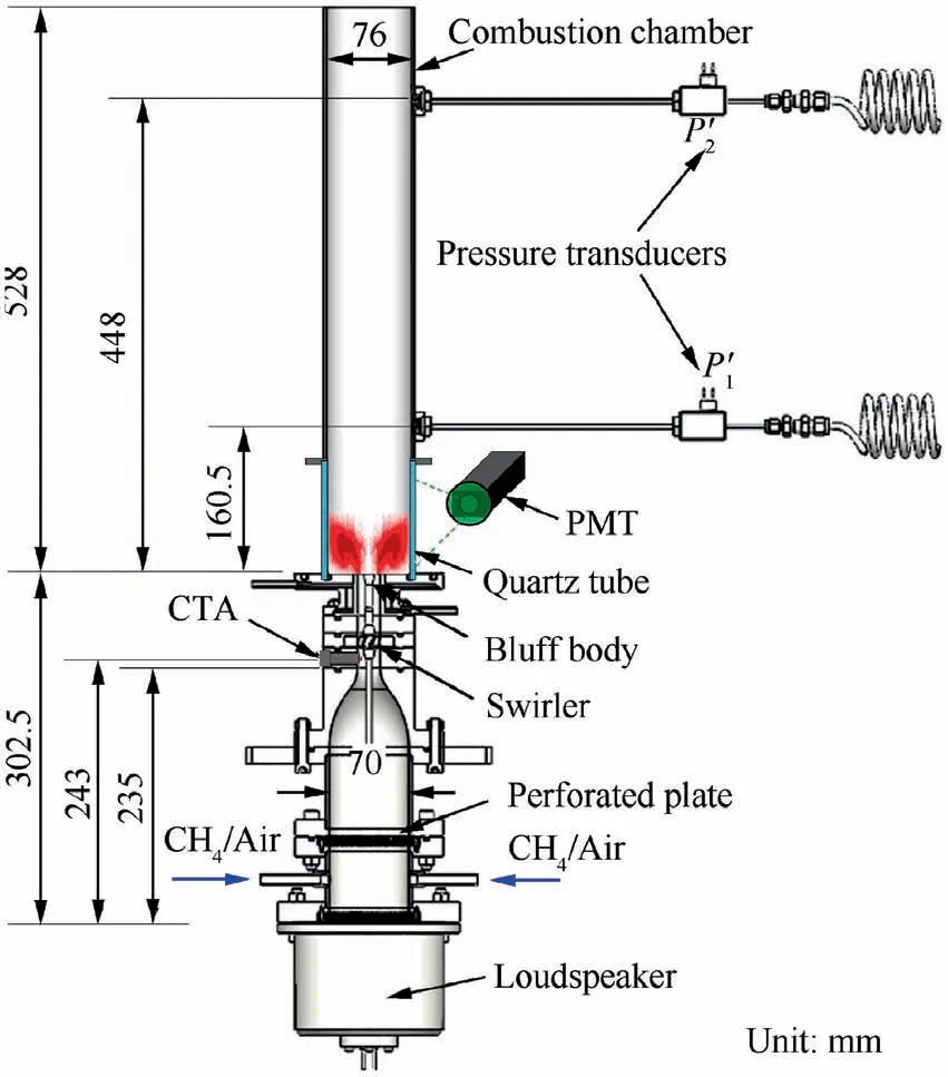
Fig. 1 Swirl combustor for studying self-excited thermoacoustic instabilities.
The controlling error of the mass flowmeter does not affect the analysis of experimental results,because the static air pressure at the upstream of the test rig is stabilized with two big tanks with a total volume of 5 m.It ensures that the mass flowmeters work in a stable state. The fuel gas is supplied with high pressure gas cylinder, which also guarantees the stability of fuel gas flow.As has been mentioned above that the pressure wave is measured with the semi-infinite-tube. The P(see Fig. 1) is applied to analyze the experimental results in the following.However, Pis an indirect measurement, which exists deviations with the pressure in the combustion chamber. To get the measuring error of the pressure signal, the semi-infinitetube method are corrected. Firstly, in the cold flow, the loudspeaker is used to produce sound waves in the frequency range of 50–500 Hz,which is of interest in the present work.Secondly,two semi-infinite tubes and two transducers are directly set at the combustion chamber. The transducers are mounted opposite to the semi-infinite tubes in the same axial position. In the experiment, we also have changed the excitation voltage of the loudspeaker to modulate the pressure amplitude.At last,we obtain the correction factor of P/Pthat is shown in Fig.2.Pis directly measured pressure and Pis the pressure based on semi-infinite tube method. In Fig. 2, the line represents the mean value and the gray shading is the error band.Then,under hot conditions, the factor of P/Pwill be used to correct the measurement with semi-infinite tube method.
2.3. Swirler position
Fig. 3 shows the strategy of changing the swirler’s position.The section of the swirling flow applies modular design so that the time delay between the upstream perturbation and the flame is adjustable. Three cases with three different locations of the swirler are adopted as shown in Fig. 3, which are Case#1 with L=-15 mm,Case#2 with L=0 mm,and Case#3 with L= +15 mm. The swirling distance in Case #1 is the same as that in Case#2.The mixing length at the upstream of the swirler in Case#1 is 15 cm longer than that in Case#2.The total mixing lengths of Case#1 and Case#3 are the same,while the swirling mixing distance in Case #3 is 15 cm longer than Case#1 and Case#2.Therefore,three sets of experiments are conducted under three swirler positions, respectively. The mass flow rate of the premixed air/methane mixture is fixed at 80 SLM. The equivalence ratio φ is changed in the range of 0.65 to 0.80. Comparing results from the three cases, the effects of the swirl mixing distance on combustion dynamics will be concluded.
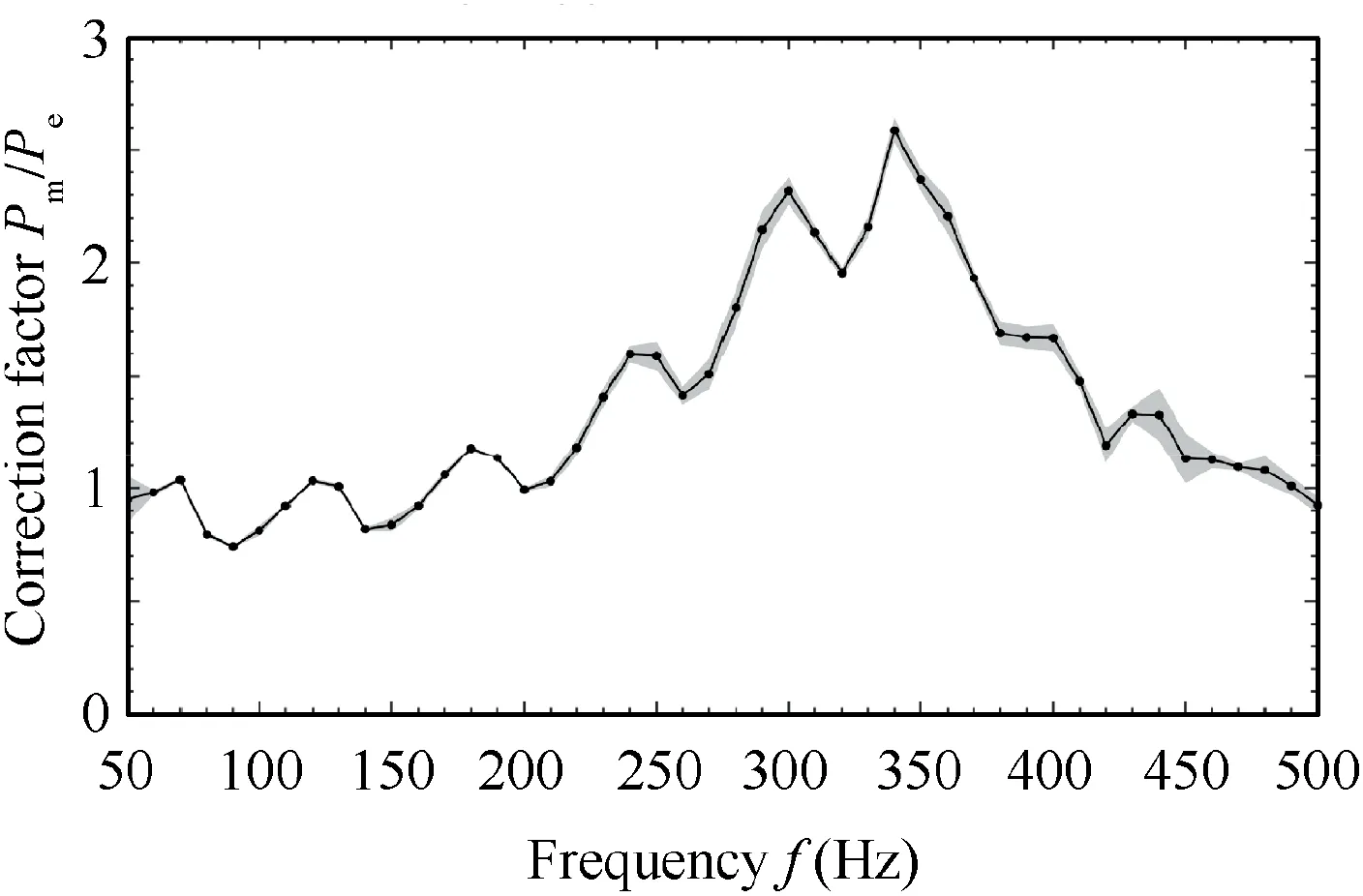
Fig.2 Correction factor of acoustic pressure measured by semiinfinite tube.
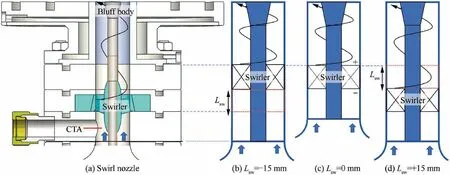
Fig. 3 Schematic diagram of modulation of swirler position.
3. Discussion
3.1.Experimental results of Self-excited combustion instabilities
The experimental results of the self-excited combustion instabilities are shown in Fig. 4. Fig. 4(a)–(c) show the raw data of pressure fluctuation P’ as a function of time t in five seconds. Fig. 4(d)–(f) are Fast Fourier Transform (FFT) spectrums of pressure oscillations.
In Fig. 4, the pressure waves in the combustion chamber differ a lot with varying operating conditions and swirl mixing distances.Two thermoacoustic modes are observed in the FFT spectrums.The general characteristics of the combustion instabilities with the variation of equivalence ratio are similar for Case #1 and Case #2 but different for Case #3. Fig. 5 shows the frequencies and the amplitudes of the two modes. In Case#1, the frequency of the first thermoacoustic mode increases from 253 Hz to 296 Hz as φ increases from 0.65 to 0.70.The pressure amplitude drops from 875 Pa to 118 Pa. As φ improves further to 0.75 and then 0.80, the mode shifts from 296 Hz to the second mode with a frequency of 201 Hz and 207 Hz, respectively. Correspondingly, the pressure amplitude reduces to less than 10 Pa as φ = 0.75 and then enhances to higher than 200 Pa when φ=0.80.In Case#2,the characteristic of combustion oscillation is similar to that in Case #1. In the above two cases,mode switches from the first mode to the second mode as φ increases from 0.65 to 0.80. However, in Case #3, the first mode, with a frequency range of 270 Hz to 309 Hz,always dominant the combustion dynamics.The pressure descends monotonously from 417 Pa to 13 Pa. In Fig. 5,the mode frequency generally rises with the increase of the equivalence ratio. This is due to that the improvement of the temperature enhances the sound speed in the combustion chamber. Besides, when increasing the equivalence ratio in the range of φ < 1, the flame is shortened and thus the time delay becomes smaller, which can lead the higher mode frequencies in a specific range.
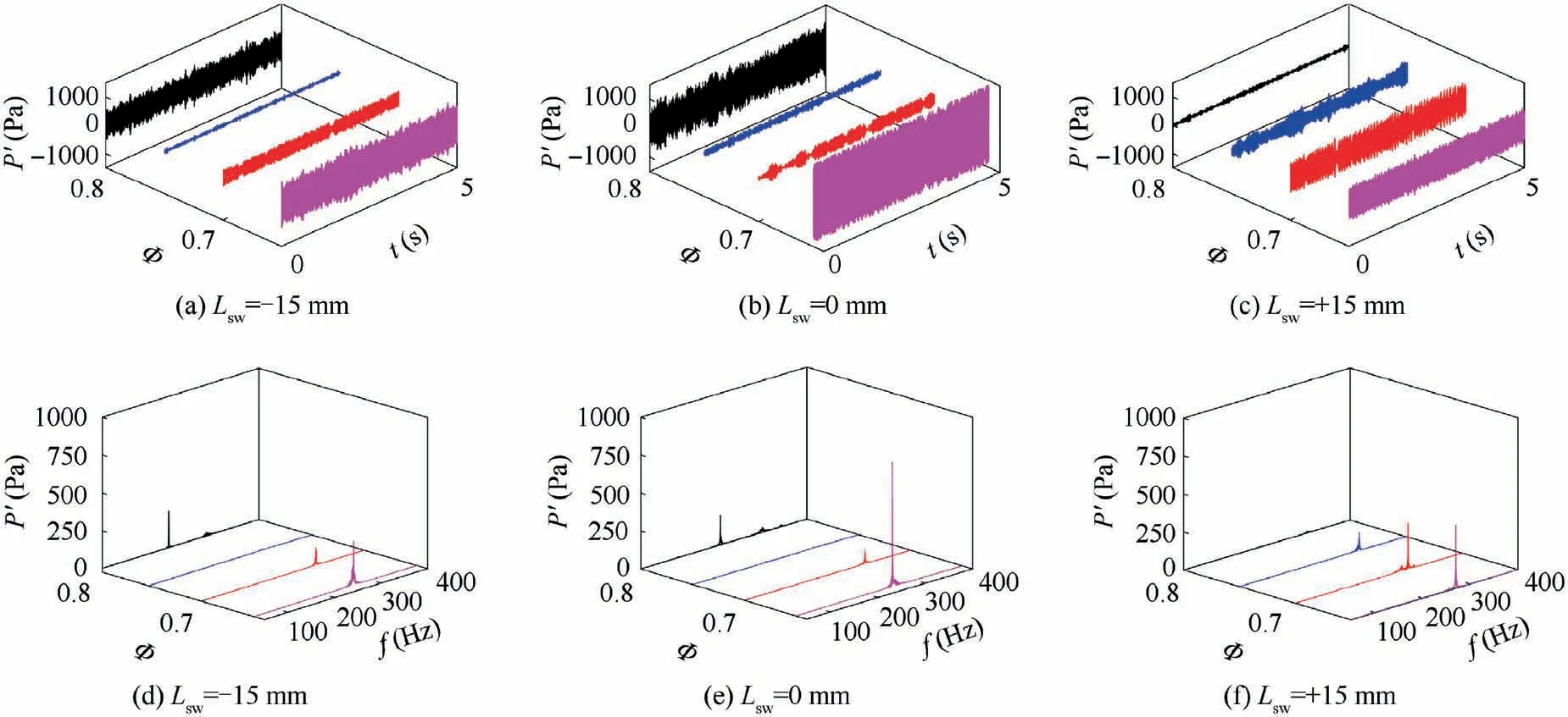
Fig. 4 Signals of combustion instabilities in three cases: (a)–(c) show raw data of pressure waves P’ and (d)–(f) are FFT spectrums of presure waves.

Fig. 5 Combustion instabilities as a function of equivalence ratio φ under three swirler positions. Case #1: ˚and ●Lsw = -15 mm;Case #2:▲Lsw = 0 mm; Case #3: ■Lsw = +15 mm.
Then, it can be concluded that the variation of the mixing length at the upstream of the swirler has no essential effects on combustion instabilities.However,the variation of the mixing length of the swirling flow can significantly change the combustion dynamics.It demonstrates that both thermoacoustic modes are driven by the feedback loop between the perturbations from the swirler and the unsteady flame.Changing the swirl mixing length means to vary the time delay of the feedback loop. As a consequence, the combustion instabilities and the flame response are changed.In the following,the flame transfer functions (F)will be measured to study the effects of the swirler position on the flame response. Finally, it will also be analyzed whether essential differences exist in the physical mechanisms of the two thermoacoustic modes with a low order model.
3.2. Flame transfer function
The flame transfer function F is commonly used to feature the flame response. The F is defined as the ratio of relative heat release rate fluctuation to the relative velocity perturbation at an upstream location:
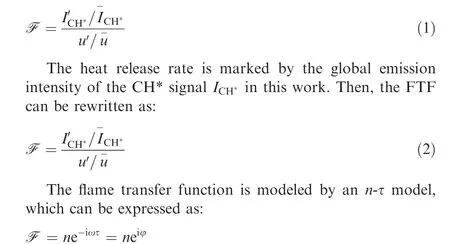
where n is the gain and τ the time delay, ω the angular frequency and φ the phase of F. The gain n is also called as the interaction index,which reflects the response level of the flame to acoustic perturbations.The time delay τ represents the time difference between the reference location and the flame.It can be determined by the FTF phase, which can be written as φ = –ωτ = –2πfτ. In this study, the flame transfer functions are measured at φ = 0.70, φ = 0.75 and φ = 0.80 under the three swirler positions, respectively. And, it needs to be noted that the length of the flame tube is 115 mm when measuring the FTF,which is just equal to the length of the quartz tube. The steel tube at the downstream of the quartz tube is dismantled to avoid self-excited combustion oscillations. In all measurements of F, u/u- is fixed at 0.1. The curves of F as a function of frequency are shown in Fig. 6(a). Based on the phase curves, global time delays are obtained in Table 1.
In Fig.6(a),for L=0 mm and L=–15 mm,the lines of the gain are similar on the whole and the phase lines are almost overlapped. The first peak of the gain curves appears at about 100 Hz.Then,the gain decreases to a local minimum near 150 Hz and followed by the second peak at 200 Hz.As the frequency increases to 350 Hz, the response level declines on the whole, though a third small lift occurs in the range of 300 Hz to 350 Hz.The local peaks of the F-curves are attributed to the combined affections of multiple perturbations with different time delays, which have been detailly investigated in Refs. 18,28–29. The above trend shows that the flame transfer function has the typical low-pass property,which has been also found in other works.The low-pass property is physically related with the driven mechanism of the flame response.For a velocity sensitive flame, the disturbances of the heat release rate are caused by the vortex shedding, which is induced by the acoustic waves. When the vortex rings interacted with the flame surface,the flame area is changed accordingly. As a result, the heat release rate is varied. For a disturbance with a low frequency, the dimension of the vortex is not far from that of the flame, therefore the interaction is sensitive.For a high frequency,the dimension of the perturbation is too small and easy to be dissipated in the reaction flow.This makes it difficult to have a significant effect on the flame dynamics. In short, it indicates that the low-pass property of the flame response is favorable for a low frequency oscillation,but unfavorable for a relatively high frequency oscillation.Because flame response is relatively weaker under a high frequency.
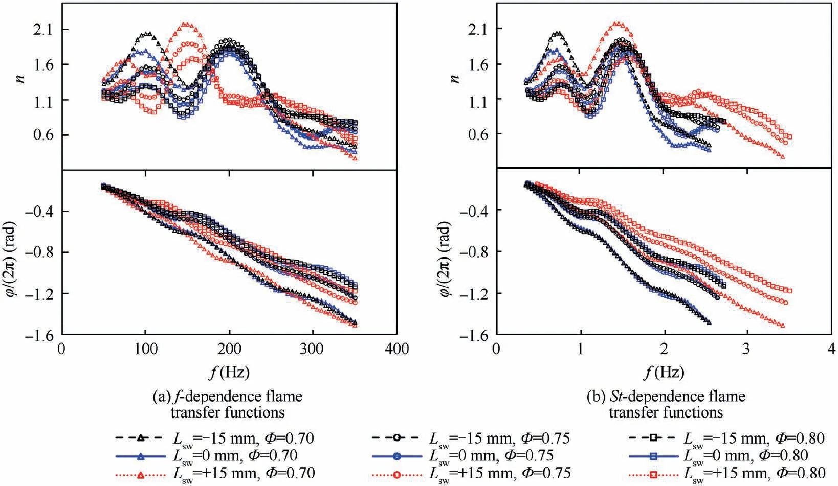
Fig. 6 Flame transfer functions under different locations of swirler.

Table 1 Global time delay of swirl combustion system.
Fig. 6 also shows that the modulation of the equivalence ratio has effects on the amplitude of the FTF gain, but little effects on the overall trend. It is mainly attributed to the change of the flame temperature and the flame speed, etc. As the rise of the flame temperature and the increase of the flame speed,the heat release rate is more powerful and the flame surface is more crinkled. As a consequence, the flame response tends be more saturated. Therefore, the gain tends to decline as the increase of the equivalence ratio. The equivalence ratio also has some effects on the phase curves.As the flame temperature and the flame speed are increased with the increase of φ,the time delay is reduced,which can be seen in Table 1.When φ increases from 0.70 to 0.80, the time delay is monotonously reduced from 4.23 to 3.16 ms as L= 0 mm and almost the same as L=–15 mm.Correspondingly,no remarkable variations of the phase curves are found in Fig. 6(a) when Lis changed from 0 mm to -15 mm. It indicates that increasing the mixing length at the upstream of the swirler in a limit range has no essential effect on the flame response. As a consequence, the combustion instabilities are not remarkably changed,which have been shown in Section 3.1.When Lchanges from 0 mm (or –15 mm) to + 15 mm, both the gain and the phase are distinctly modulated. Firstly, in Fig. 6(a), peaks and valleys of the gain curves are shifted to the direction of the low frequency. For instance, the first peak shifts from 100 Hz to 75 Hz, and the second peak moves from 200 Hz to 150 Hz. Secondly, the phase curves are changed with the variation of equivalence ratios. As a result, global time delay is increased (see Table 1).
To further analyze the effects of the swirler position on the flame response,we define a Strouhal number as St=f∙l/U,where lis the swirl mixing distance, which is defined as the distance from the trailing edge of the swirler to the inlet of the combustion chamber,Uis the bulk velocity in the mixing channel, which changes little in various conditions. When L= 0 mm and L= –15 mm, lequals to 42 mm; when L= +15 mm, llengthens to 57 mm. Then, the Stdependent flame transfer functions are obtained and shown in Fig. 6(b). All the gain curves show the same trend and the positions of peaks and valleys are well matched on the St axis,particularly for the same equivalence ratio.It indicates that the modulation of the gain curves in Fig.6(a)has a direct correlation with the change of the swirling distance. The peaks and valleys seem to be stretched with a factor of l/(l+ 15).Simultaneously, the St-dependent phase curves are stretched to the same trends with the results as L= 0 mm or L=–15 mm.The deviations in the slope of the phase curves reflect the variations of the global time delay.
In Section 3.1, we have mentioned that the first mode is about 300 Hz and the second mode is around 200 Hz. In Fig. 6(a), as L= 0 mm and L= –15 mm, the maximum value of the gain varies in the range of 1.75 to 1.95. And the corresponding frequency is exactly around 200 Hz. However,the gain at 300 Hz is much smaller, which is in the range of 0.43 to 0.86.For a fixed velocity perturbation, the higher gain at 200 Hz means the greater the heat release rate fluctuation of the flame at this frequency. When L= +15 mm, the mode near 200 Hz becomes stable at all three equivalence ratios.This can be attributed to the changes in the gain and time delay of the flame response.The gain is roughly equivalent to 1.95 near 200 Hz as L= –15 mm or 0 mm and dropped dramatically to 1.05 as L=+15 mm.It can be concluded that the sharp drop in the interaction index can significantly change the combustion instabilities. The increase in the time delay leads to a decrease of the mode frequency. The increment of the time delay when Lchanges from 0 mm to+15 mm is in the range of 2.3%to 4.5%.It also has some effects on the thermoacoustic instabilities. It demonstrates again that the second mode has a strong correlation with the flame response. Based on the above phenomena and the results from our previous works,the mode near 200 Hz is the intrinsic thermoacoustic mode, which is predominated by the flame. The mode near 300 Hz is the quarter-wave mode of the combustion chamber.
In conclusion, the location of the swirler has essential effects on the flame response and the self-excited combustion instabilities. The gain curve is compressed or stretched by changing the swirling distance. The phase curve is changed in the slope and thus induces an increment of the time delay.Therefore, it is easy to understand the mode transition of the combustion instabilities that have been shown in Figs. 4 and 5. Furthermore, the falling of the gain probably plays an important role in eliminating the combustion oscillation of the ITA mode. This inference may be further confirmed and explained by the low order modeling of the thermoacoustic system in the next section.
3.3. Modeling of the thermoacoustic system
3.3.1. Modeling description
Generally, combustion instabilities can be qualitatively analyzed with a low order modelwhen the flame response is known. In this section, the thermoacoustic system of the swirl combustor is modeled in the framework of a linearized acoustic network, which is sketched as Fig. 7.
Considering the longitudinal thermoacoustic mode in this study,the sound propagates in the combustor as planar waves,including waves traveling upward and downward. The downward and upward waves can be written in the forms of Aeeand Bee, respectively. Where ω is the angular frequency, c is the speed of sound and k = ω/c is the wavenumber. In the frequency domain, the traveling waves in opposite directions can be expressed as f = Aeand g=Be.Then,the acoustic pressure waves can be written as
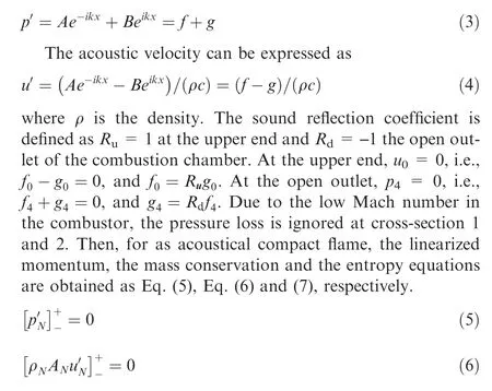
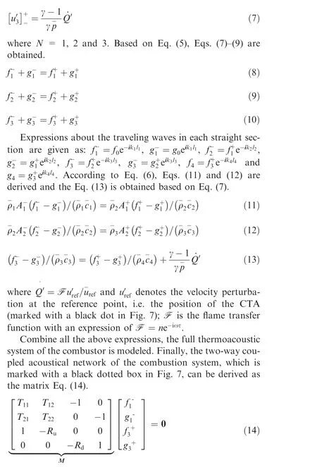
where T is the acoustic transfer matrix from the inlet of a constricted throat of the channel to the position of the flame. The thermoacoustic mode of the system will be given if det(M)=0 has a non-trivial solution when Rand Rare not equal to zero. Table 2 gives the input parameters for solving the problem. In the network model, if the flame transfer function F is set as zero, the model gives the pure acoustic modes of the combustor; if F is modeled with the n-τ model, the full thermoacoustic modes are given.
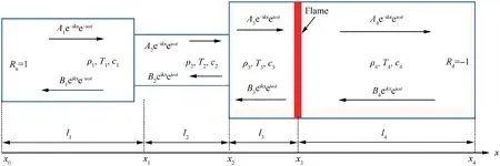
Fig. 7 Low order modeling diagram of swirl combustor with changes in cross-section.
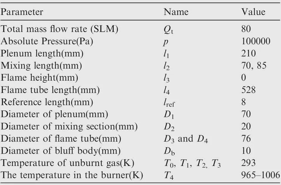
Table 2 Input parameters of low order model.
3.3.2. The acoustic modes of the system
In this section,the theoretical analysis of combustion instabilities is conducted with the simplified acoustic network model.The input parameters for the modeling are listed in Table 2.It needs to be noted that the length of the plenum lis corrected as 210 mm considering the contraction section and the perforated plate in the plenum. Firstly, the flame response is modeled with an externally forced flame transfer function from the experiment. Then, to give a further explanation of the results,the flame response will also be modeled with the simply n-τ model, which is in the form of F = ne.
(1) With the measured flame transfer function
With the measured flame transfer functions(see Fig.6),the predicted combustion instabilities of the full thermoacoustic system are given in Fig. 8. The subfigures of 8(a), 8(b) and 8(c) corresponding to the three cases of L= - 15 mm,L= 0 mm and L= +15 mm, respectively. The positive growth rate means that the predicted thermoacoustic mode is unstable; otherwise, the mode is stable. In the model, the frequency is limited to the range of 50–400 Hz,which is of interest to this study. Then, three thermoacoustic modes are given in Fig. 8 for all the three cases. Based on previous works,the mode near 100 Hz is the Helmholtz mode of the upstream plenum and the mode near 300 Hz is the quarter-wave mode of the combustion chamber.Furthermore,the second mode from the model,with a frequency between 130 Hz and 200 Hz can be identified as the intrinsic thermoacoustic mode. It was concluded that the number of the full thermoacoustic modes is the sum of that of the cavity acoustic modes and the ITA mode.The ITA mode predicted in the calculation corresponds to the second mode in the experiment, with a frequency near 200 Hz. Similarly, the third mode from the model also can be found from the experiment. The Helmholtz mode from the model is insensitive in the experiment.This may be due to two aspects:(A)the pressure of the Helmholtz mode is too weak to be detected in the combustion chamber;(B)the Helmholtz mode keeps stable at all the conditions even the model gives a positive growth rate.
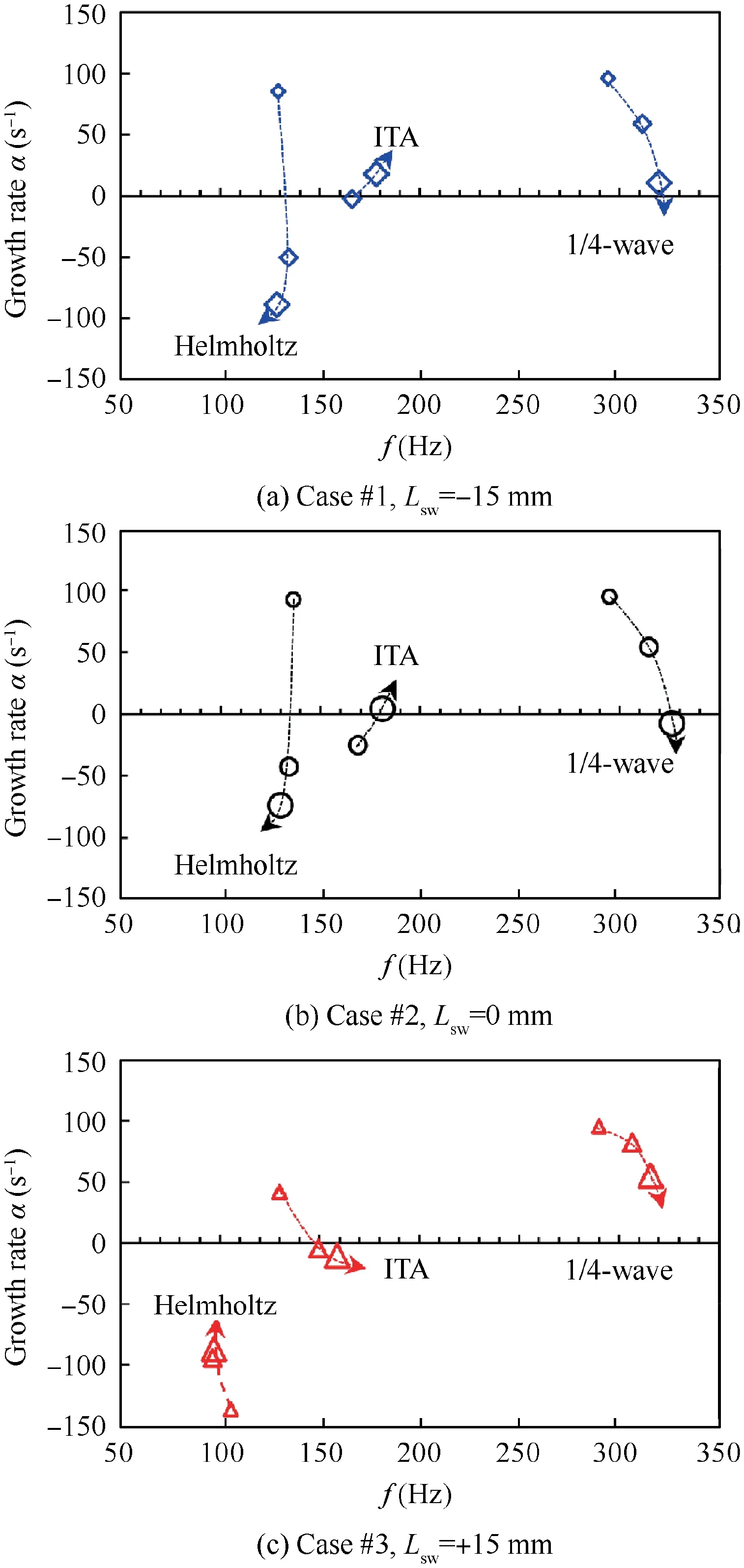
Fig. 8 Thermoacoustic instabilities of combustion system from modeling. The size of the marker represents the value of the equivalence ratio. The smallest marker denotes φ = 0.70 and the largest represents φ = 0.80.
In Fig.8,the trends of the combustion instability of the 1/4 wave mode are similar for all three cases. The frequency increases with the enhance of the equivalence ratio. The growth rate decreases with the increase of the frequency. The increment of the frequency is mainly attributed to two factors.One is that the increase of the equivalence ratio enhances the gas temperature and, subsequently, the sound speed in the combustion chamber. The other factor is that the increased flame speed and the shortened flame height cause a smaller time delay; consequently, the frequency of the thermoacoustic mode is increased. The decrease in the growth rate demonstrates that the coupling between the flame and the acoustic of the 1/4 wave mode becomes weaker when the frequency increases. This is due to changes in the flame response.
For the ITA mode, the frequency also increases with the increasing equivalence ratio. Because the frequency of the ITA mode is directly determined by the time delay..The rising equivalence ratio causes a decrease in the time delay,thus the frequency of the ITA mode is reduced.The f-α trajectories of the ITA mode present a different trend for different swirl mixing distance. In Case#1 or Case #2 (see Fig. 8(a)and (b)), the growth rate increases with the raise of the frequency. However, it decreases with the increase of the frequency in Case #3 (see Fig. 8(c)). The f-α trajectories for the Helmholtz mode are also in a different direction for the two positions of the swirler.In Case#1 or Case#2,the growth rate monotonously decreases with the increase of the equivalence ratio but the frequency only changes in a small range.In Case#3, however, the growth rate monotonously increases and the frequency significantly reduces with the equivalence ratio.
The above-mentioned modeling results are consistent well with that of the experiment in general.Firstly,both the experimental and the model results show that the 1/4 wave mode tends to be stable as φ increases from 0.70 to 0.80 for all three cases. In the experiment, the amplitude of the oscillation decreases as φ increases. Correspondingly, the growth rate monotonously declines in the modeling. Secondly, in Case #1 or#2,the ITA mode is aroused from a weak signal to the fluctuation with large amplitude in the experiment as φ increased from 0.75 to 0.80. Accordingly, the growth rate of the ITA mode increases from negative to positive from the modeling.In Case #3 as φ = 0.70, the predicted ITA mode is unstable at 130 Hz, which is exactly the frequency of the signal with a low amplitude extracted from the experiment. As φ = 0.75 and φ = 0.80, the ITA mode is stable both in the model and the experiment.
The results predicted by the model are not matched well with that of the experiment for some conditions.For example,there is a remarkable difference between the predicted frequency of the ITA mode and that of the experiment. Another deviation is that the 1/4 wave mode is stable as φ = 0.75 in Cases #1 and #2 in the experiment while it is unstable in the model.This can be analyzed from two aspects.The one is that the low order model is simplified and linearized. Accurate boundary conditions and operating conditions are difficult to be obtained and modeled. The other is that the flame transfer functions of the externally forced flame in a small perturbation deviate apparently from that of the self-excited flame.The combined effects lead to the underestimation of the ITA frequency and the overestimation of the frequency of the quarter-wave mode. Besides, the mode switching between ITA mode and the 1/4 wave mode in Cases #1 and #2 may associate with a nonlinear effect that is not able to be predicted in the present model.
(2) With n-τ modeled flame transfer function
The modeling with measured flame transfer functions effectively predicts the frequencies and instabilities of the modes in the above cases. It explains why the ITA mode became stable after the swirl mixing length is increased. For the measured FTF, the gain and phase change simultaneously with the frequency. Therefore, it is difficult to draw an exact conclusion on how the gain and phase affect the combustion instabilities.Then,the simple n-τ model is applied to model the interaction of the flame and the perturbation.The results for Case#2 and Case #3 are shown in Fig. 9.
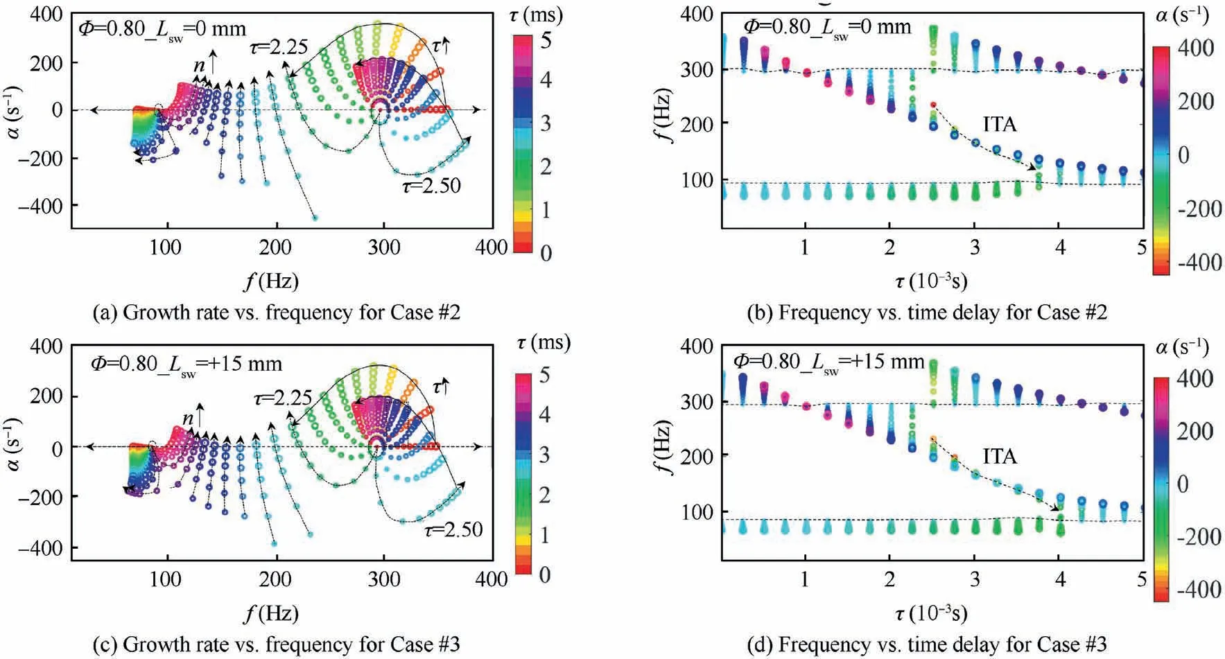
Fig. 9 Modeling results of Case #2 ((a) and (b)) and Case #3 ((c) and (d)) with the simple n-τ model. n (expressed with the size of the circle) changes in the range of 0–2 and τ in the range of 0–5 ms.
In the simplified flame model, which is F = ne, n changes in the range of 0–2 and τ in the range of 0 to 5 ms.Fig.9(a)and(c)show the f-α trajectories of the thermoacoustic modes under various time delays for the two cases. Fig. 9(b)and (d) show the τ-f trajectories under various interaction index. A general observation of the results from both cases is that the predicted thermoacoustic modes can be unstable and stable when varying n and τ. The instabilities of the modes are very sensitive to the interaction index and time delay.When the gain and the time delay both equal to zero, two modes are given. The first is around 100 Hz and the second near 300 Hz. These two modes are the pure acoustic modes of the combustor because the flame is not coupled with the acoustic field. The first mode is the Helmholtz mode of the plenum at the upstream of the swirler and the second mode is the quarter-wave mode of the combustion chamber. As the interaction index is low (e.g., n = 0.2), two thermoacoustic modes are identified at various time delays. The frequency of each mode varies in a limit range with the increase of the time delay, which can be found in Fig. 9(b) and (d). Correspondingly, the f-α trajectory forms into a circle. When n increases further, an additional thermoacoustic modes split from the 1/4 wave mode as the time delay is larger than 2.5 ms in both cases. With further increase of the time delay (τ ≥4 ms for Case #2 and τ ≥4.25 ms for Case #3), the ITA mode merges with the Helmholtz mode, and thus, only two modes exist in the thermoacoustic system again. This provides a reasonable explanation for the results from the experiment or the modeling mentioned above that no ITA mode is identified as φ = 0.70 but one ITA mode is found as φ = 0.75 and 0.80.In Fig. 9, the frequency of the ITA mode decreases monotonously with the increase of the time delay. The growth rate monotonously increases with the increase of the gain. For the condition with a fixed time delay, when the ITA mode approaches the Helmholtz mode, the frequency increases with the increase of the gain;on the contrary,as it closes to the 1/4 wave mode, the frequency reduces with the increase of the gain. This explains why the f-α trajectories of the Helmholtz mode and the ITA mode present the opposite trends in Fig.8(b)and(c).Fig.9 also shows that the ITA mode is more prone to be unstable in Case #2 than that in Case#3. In Case#2 (see Fig. 9(a) and (b)), the growth rate of the ITA mode becomes unstable as n is greater than 1.5. However, in Case#3, triggering of the ITA mode requires a gain of about 2.Recall the flame transfer function in Fig. 6, we can find that the maximum of the gain is in the range of 1.5–2 in Case #2 and the corresponding frequencies are close to those of the ITA modes in the experiment. However, in Case #3, the max gain is lower than 1.9 as φ = 0.75 or φ = 0.80. This clarifies the reason why the ITA mode changes from unstable to stable when the swirling distance is increased from 70 to 85 mm.According to the results from the two modeling and the experimental, the conclusion can be confirmed that the ITA mode is a flame-dominant mode. It infers that when the ITA mode is triggered, the heat release rate will oscillate in a large amplitude. Specifically, the area and location of the flame will change dramatically.The interaction between sound waves and the unsteady flame tends to produce a nonlinear effect.
4. Conclusions
The effects of the swirl mixing distance on the combustion instabilities, particularly the intrinsic thermoacoustic mode(ITA), is experimentally and theoretically investigated in this paper.The position of the swirler has significant effects on the instabilities on the ITA mode,but the weak influence is observed in the quarter-wave mode. It indicates that the intrinsic thermoacoustic instability is driven by a local feedback loop.
The flame transfer functions(FTFs)are measured at different equivalence ratios under various swirl mixing lengths.The FTFs show that the swirl mixing length has remarkable effects on the peak positions of the FTF again and the specific effects on the FTF phase.The gain curves are likely to be stretched by increasing the distance from the swirler to the entrance of the combustion chamber.
Modeling results show that the variation of the time delay and gain due to the modulation of the swirl location changes the frequencies and growth rates of thermoacoustic modes.The cavity acoustic modes are closely related to the pure acoustic modes of the combustor but the ITA mode is different.The intrinsic thermoacoustic instability is directly driven and dominated by the flame.
Combining the experiment and the modeling,it can be concluded that the ITA mode may be raised in a combustor if two conditions are satisfied: the time delay is within the appropriate range and the FTF gain is large enough.
The authors declare that they have no known competing financial interests or personal relationships that could have appeared to influence the work reported in this paper.
This study was supported the National Natural Science Foundation of China (Nos. 51676126 and 51776191).
