Effects of forward-flight speed on plume flow and infrared radiation of IRS-integrating helicopter
Zongyao YANG, Jingzhou ZHANG, Yong SHAN
Key Laboratory of Thermal Management and Energy Utilization of Aircraft of Ministry of Industry and Information
Technology, College of Energy and Power Engineering, Nanjing University of Aeronautics and Astronautics, Nanjing 210016, China
KEYWORDS Exhaust plume;Forward-flight speed;Helicopter;Infrared radiation;Integrating infrared suppressor
Abstract To address deeper understandings about the aero-thermal performance of an integrating infrared suppressor under more realistic situations,a numerical investigation is motivated in the current study, concerning the effects of forward-flight speed on exhaust plume flow and infrared radiation of the Infrared Suppressor-integrating(IRS-integrating)helicopter,wherein the forward-flight speed is changed from 0 m/s(hover state)to 100 m/s,while both the engine exhaust parameters and the main-rotor operation parameters remains unchanged during different forward-flight velocities.The results show that the interaction between forward-flight flow and downwash flow alters the exhaust plume development and the internal flow inside the IRS-integrating rear fuselage more complicatedly,tightly dependent on the forward-flight speed.Of particular concern is the situation where the forward-flight flow has nearly the same level as the downwash flow, the hot mixing flow could possibly interacts with the helicopter rear fuselage to play a local heating effect. With the increase of forward-flight speed, the ejection coefficient is generally increased and the average exhaust temperature of mixing flow is decreased, leading to a reduction of the infrared radiation intensity of exhaust plume in 3–5 μm band.However,the influence of forward-flight speed on the overall infrared radiation intensity of IRS-integrating helicopter is conjectured not monotonous due to the complicated interaction between forward-flight flow and downwash flow.Under high-speed forward-flight states, the overall infrared radiation intensity of the IRS-integrating helicopter in 3–5 μm band is reduced with the increase of forward-flight speed. With respect to 3–5 μm band,the forward-flight speed has little effect on the infrared radiation in 8–14 μm band.
1. Introduction
The helicopters usually fly with a low-attitude and low-speed fight profile. In the high-technology battlefield environment,they face to many threats form multiple spectrum targeting,such as infrared, radar and acoustic detectors.As the infrared detection is of passive tracking feature that seeks the native emitting energy of the objects,its threat to the survivability of helicopters is more crucial. With the rapid developments of infrared detection technology and the progressing increase of power-to-weight ratio of helicopter-equipped turbo-shaft engines, the infrared signature suppression becomes more and more challenging to the helicopter susceptibility.
It had been well demonstrated that the main infrared sources of helicopter include the hot components and exhaust plume of the engine,as well as the airframe skin heated by the engine and plume.To suppressthe infrared signaturelevel,an effective means is the use of Infrared Suppressor(IRS)that utilizes the exhausting momentum to pumping cold ambient air into the mixing exhaust duct,wherein the hot exhaust flow ismixed and diluted by the suctioned cold ambient air.As a consequence, both the exhaust plume temperature and the mixing-duct wall temperature are reduced.In accordance with this acceptance of infrared suppressing mechanism, vast efforts were devoted toward the highefficient mixer-ejectorand the advanced infrared suppressorduring past decades.These investigations indeed provide the designers with more comprehensive understandings about the multi-parameter influences on the aerodynamic, thermal and infrared performances of the infrared suppressor.
It was also well identified that the optical blocking of internal hot components is a very important aspect in the design of helicopter IRS.To meet the requirement of high-stealth development trend of the helicopters,a novel integrating infrared suppressor was proposed, wherein the engine exhaust system was embedded in the rear fuselage.By utilizing an integrating infrared suppressor, the infrared radiation from internal hot mixing duct is effectively concealed.To demonstrate the infrared radiation characteristics of the IRSintegrating helicopter,Pan et al.conducted numerical simulations regarding the coupling of internal flow and external flow of the IRS-integrating helicopter, based on a simplified rotor downwash model. The effects of engine exhaust temperature and fuselage surface emissivity on the helicopter infrared radiation characteristics under hover status were illustrated.Li and Xuanput forward an integrated methodology to consider the fuselage/engine construction coupling and energy transfer relation of the helicopter.More recently,Zhou et al.numerically studied the radar/infrared integrated stealth characteristics of helicopter with integrated infrared suppressor.
To the best of our knowledge,most of the previous researches relating to IRS were conducted by using‘‘isolated”IRS model itself, without considering its ‘‘integrated” modes in the helicopter and the ‘‘practical” external flow regimes. In the real applications, the exhaust flow was apparently affected upon the impact of external flow, as a consequence of variation of the temperature distribution and infrared radiation spatial distribution of helicopter.Therefore, a research objective is motivated in current study to illustrate the effects of forwardflight speed on the plume flow and infrared radiation of the IRS-integrating helicopter,by using a numerical methodology.From current study,deeper understandings about the IRS performance under more realistic situations are put forward.
2. Physical and computational models
2.1. Brief description of physical model
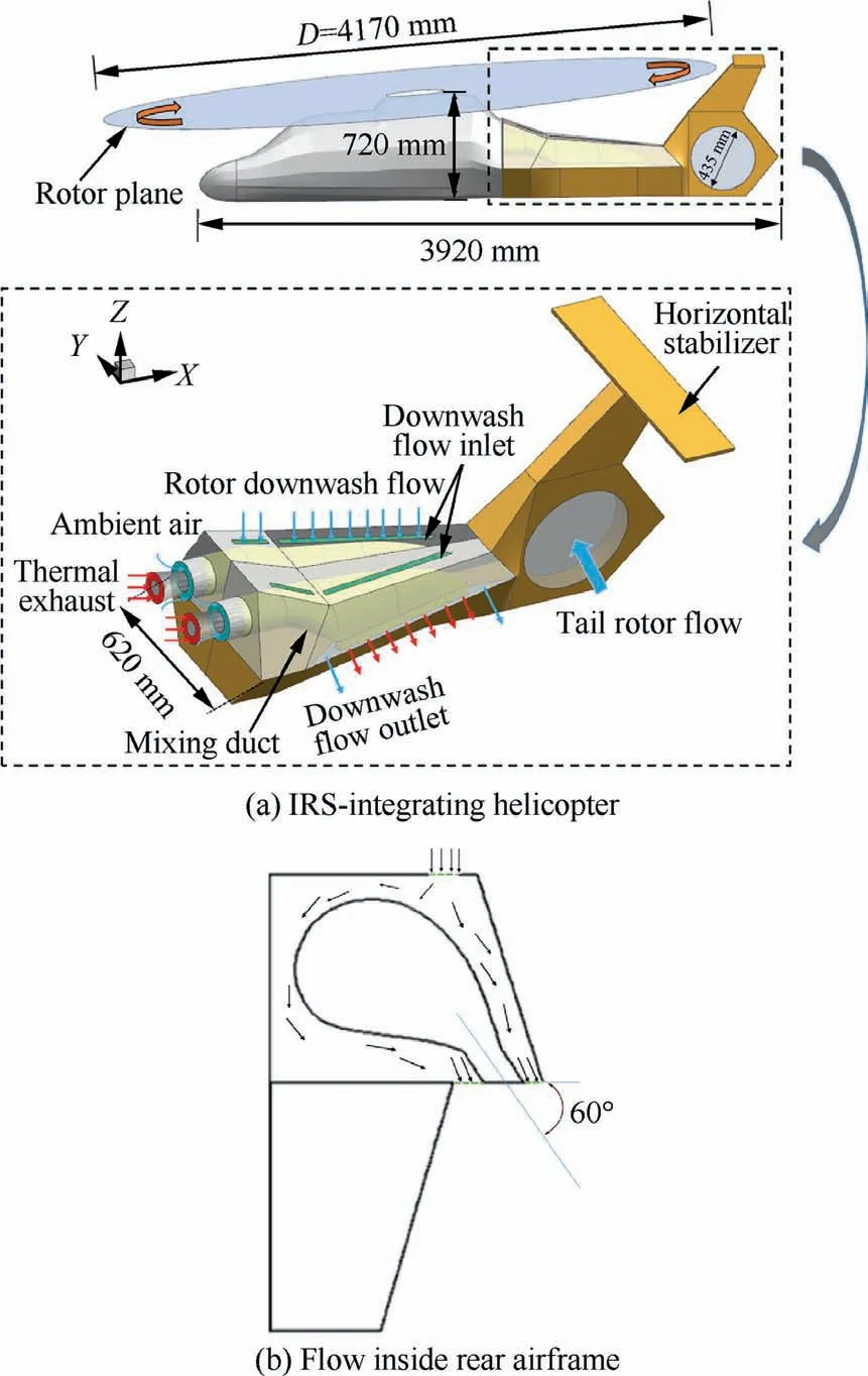
Fig. 1 Schematic of helicopter integrating infrared suppressor.
A hypothetical scaled helicopter model is taken into consideration in current study,as schematically displayed in Fig.1.The main geometrical parameters for the currently hypothetical scaled-helicopter model are listed in Table 1. Its length, width and height are 3920 mm, 620 mm and 720 mm, respectively.Twin engines are equipped in this helicopter. Both the main rotor and the tail rotor are simplified as the actuator discs.The main rotor has a rotating diameter (D) of 4170 mm and rotates in the clockwise direction.The tail rotor has a rotating diameter of 435 mm and actuates the tail-rotor airflow from the left side to the right side of the fuselage.
The exhaust system is installed inside the rear fuselage of helicopter. The rear fuselage takes on a convergent contour with varying convergent ratios along the axial direction. Twin turboshaft-engine nozzles are adopted in the exhaust system.A baffle plate is used to divide the internal space of rear fuselage into two symmetrically individual chambers, in accordance to twin exhaust nozzles. At each side, two slot-shaped inlets are arranged on the top of rear fuselage to guide the rotor downwash flow into the rear fuselage for the purpose of cooling the mixing duct.The front inlet has a length of 190 mm and width of 22.5 mm.The rear inlet has a length of 630 mm and width of 22.5 mm. For each side, the high-temperature gas after the engine’s power turbine is discharged from the main nozzle into the mixing duct. Both the exhaust flow and the rotor downwash flow are ejected from the slot outlet at the side of the fuselage, with an inclined angle of 60° relative to the fuselage.This slot outlet has a length of 700 mm and width of 70 mm.
The exhaust system is shown in Fig.2.Its main geometrical parameters are also listed in Table 1.The diameter of the mainnozzle behind the outlet of the power turbine is 80 mm. The main nozzle adopts the lobed nozzle, which is a highefficiency ejector nozzle form.Twelve lobes are evenly arranged along the circumference and the expansion angle of the lobes is 24.5°. In the integrated design of exhaust system and rear fuselage, the mixing duct has a complicated profile that transits from an initial circular inlet to the final slot outlet,to match with the internal space of the rear fuselage. Its axial length is 1100 mm. The inlet diameter of mixing duct is 144 mm and the outlet has a large aspect ratio with a length of 630 mm and a width of 33 mm.The outlet-to-inlet area ratio of mixing duct is about 1.28.
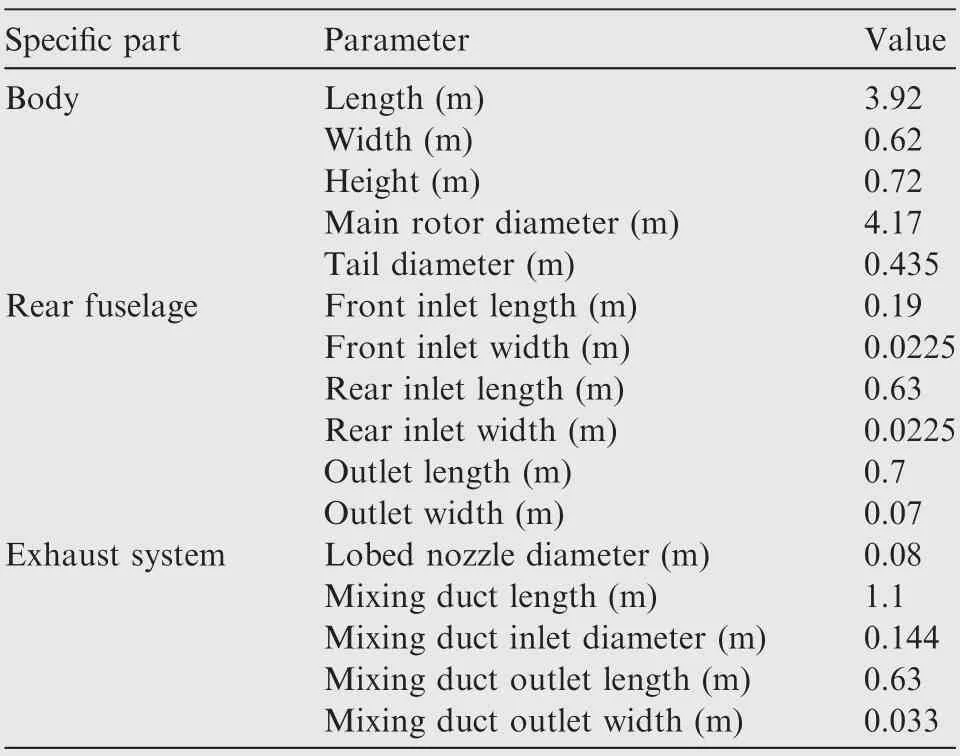
Table 1 Main geometrical parameters of IRS-integrating helicopter model.
2.2. Brief description of computational model
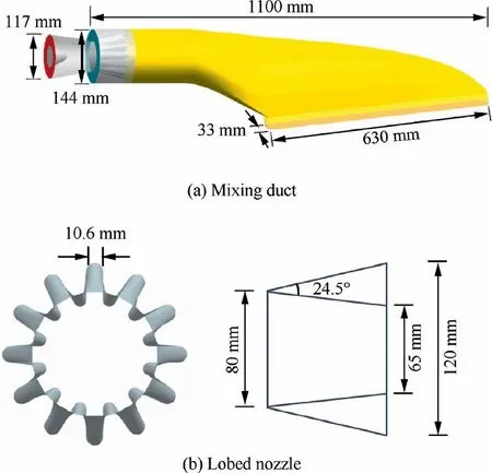
Fig. 2 Schematic of exhaust system.
Fig. 3 shows the computational model. A cubic space is selected as the computational zone, wherein the helicopter is located. The horizontal plane has a side-length of 5 times of the main-rotor diameter(that is 5D)and the height of the cubic space is 6D. In this computational model, four flows are involved,including the hot exhaust flow,the forward-flight airflow, the main-rotor downwash flow, and the tail-rotor airflow.
During current study, some simplified treatments are adopted to model the present problem, with that aim at illustrating the forward-flight speed on the plume flow and infrared radiation of the IRS-integrating helicopter, as follows:
(1) On account the many complicated factors are highlycoupled in the real flight profile, such as the ambient parameters, engine operational aerodynamic parameters, and the main-rotor operational parameters, to make the theoretical analysis on the current issue more realistic, a specific simplified treatment is made, by neglecting the variations of engine exhaust and mainrotor operation during different flight status. That is,both the engine exhaust parameters (such as the mass flow rate, pressure and temperature) and the mainrotor operation parameters (such as incidence angle of rotor blade,rotational speed)remains unchanged during different forward-flight velocities.
(2) On account that the combustion efficiency is generally higher than 0.97 in the turbo-shaft engines,the imported exhaust gas is treated as an ideal mixed gas from the complete combustion of aviation kerosene. The exhaust flow is originated from the nozzle inlet. It is composed by nitrogen, carbon dioxide and water vapor.
(3) The impact of surface emissivity on infrared radiation is not considered in current study,as it does not affect the evaluation of infrared radiation relationships between different forward-flight speeds.
In accordance to the computational model,the corresponding boundary conditions are set as follows:
The exhaust flow is originated from the nozzle inlet,as displayed in Fig. 2(a). For each nozzle, the inlet is defined as the mass-flow-inlet, with a mass flow rate of 0.342 kg/s and the temperature is set as 840 K, providing an ejecting velocity of 100 m/s approximately that matches to the actual situation of engine exhaust speed. The imported exhaust gas is an ideal mixed gas. Its mass fractions of nitrogen, carbon dioxide and water vapor are specialized as 0.706, 0.209 and 0.085 respectively, and the absorption coefficient of exhaust gas is set as 0.1 m, referring previous researches.With regard to the suctioned flow from the ejector, a surrounding static pressure at the front of mixing-duct inlet is set as the ambient pressure. Assuming that the hover or cruise altitude is 300 m, the temperature of surrounding air is set as 293 K. Besides, the injected flow is assumed to be mainly composed of nitrogen and oxygen, with corresponding mass fraction of 0.756 and 0.244, respectively.
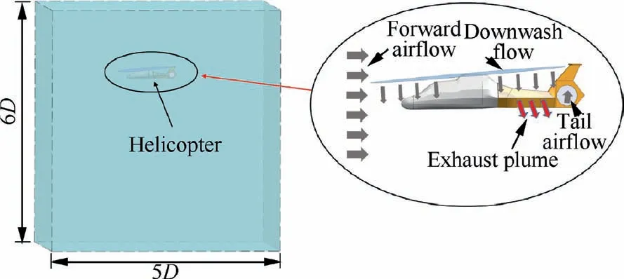
Fig. 3 Schematic of computational domain.
In the simulation of main-rotor downwash flow, a simplified ‘‘actuator disk” model is utilized. Generally, an accurate simulation of rotor downwash flow could be realized by using Multiple Reference Frame (MRF) method for the isolated main rotor, as displayed in Fig. 4(a), wherein the computational domain is divided into two zones, referred as rotational zone that encloses the rotating blades,and stationary zone that closes to the inner rotational zone.In this manner, the detailed local flow fields could be captured. It is certain that the local flow in the circumferential direction behaves significantly in the immediately downward section of main-rotor central plane, as displayed in Fig. 4(b). However, downstream a little far from main-rotor central plane, the downwash flow develops to approach a similar-rigid circulating flow feature,as displayed in Fig. 4(c). Therefore, a simplified approach by utilizing ‘‘actuator disk” is realistic for modelling the mainrotor downwash flow in the investigations of flight aerodynamics and infrared radiation of helicopters.On account that the‘‘actuator disk”model has an obvious advantage on saving the computational grids, it is applied in the current study.

Fig. 4 Rotor downwash flow simulation with MRF method.
The main-rotor downwash flow is deduced by using an‘‘actuator disk” model, same as that adopted by Pan et al.It passes through the rotation plane with an induced velocity(v) perpendicular to the blade chord line, as displayed in Fig.5(a).With respect to the actuator disk,this induced velocity could be deposed as two velocity components,namely,vertical component perpendicular to actuator disk (v) and the tangential component parallel to actuator disk (v), such as v=vcosφ and v=vsinφ, here φ is the incidence angle of rotor blade with respect to the actuator disc, which is set as 10°in current study.In addition,the induced velocity distribution along the blade radial direction is assumed to be increased linearly from the center to a position of 80% blade radius and then decreases linearly to zero at the blade edge,as displayed in Fig. 5(b). It the current study, the mean downwash flow velocity is set as 15 m/s. Fig. 5(c) presents a comparison of the velocity distribution between the actuator-disk-based simulation and the MRF-based simulation for an isolated rotor, at a downward section of 0.05D apart from the from main-rotor central plane. It is confirmed that the ‘‘actuator disk” model is realistic for modelling the main-rotor downwash flow in the simulations of infrared radiation of helicopters.
With regard to the tail-rotor airflow, a simple throughout flow scheme is adopted with a uniform velocity of 12 m/s,which is directed to the right side of the fuselage.
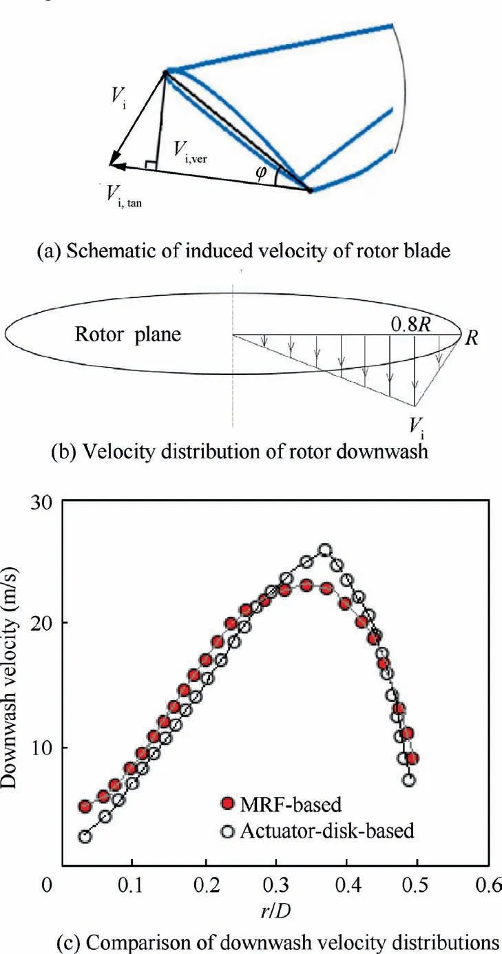
Fig. 5 Rotor downwash flow mode.
The boundaries at the cubic space are set as the pressure outlet under the helicopter hover status (that is zero-speed forward-flight case).While under the forward-flight status,the boundary condition at the front plane of cubic space is replaced by a velocity-inlet and the rear plane of cubic space.For simplicity, all of the solid walls in the helicopter body are treated as zero-thickness walls,that is,the thermal conduction heat transfer inside the solid wall is ignored.Only the convection heat transfer and the radiation heat transfer are concerned to determine the surface temperature on the solid walls. All solid-wall surfaces are treated as gray-diffuse surfaces, with a fixed emissivity of 0.8.
3. Computational methodology
3.1. Flow field simulation
Firstly, a three-dimensional CFD simulation is conducted to determine the flow and temperature fields, in accordance with the computational model.The governing equations include the mass conservation, momentum conservation and energy conservation equations, as well as the species transport and radiation heat transfer equations. These equations are described in details by Li et al.
Considering an irregular helicopter fuselage and a wide computational zone, a mixed computational mesh is adopted in the current study, by dividing the computational zone into three local regions. They are the internal flow region inside the exhaust nozzle, the near-field region around the helicopter and the far-field region enclosing the near-field region. In the exhaust nozzle and the near-field region, unstructured grids are used to fit the corresponding wall surface. While in the far-field region, structured grids are used, as displayed in Fig. 6. Mesh refinement is applied to the near-wall layer to ensure that the dimensionless normal distance ynear the wall satisfy the requirement of the turbulence model.
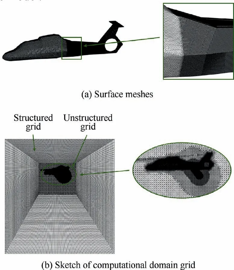
Fig. 6 Computational grids in CFD.
The CFD simulation is conducted by the use of commercial software ANSYS Fluent 14.0.According to Pan et al.the Shear Stress Transport k-ω (SST k-ω) turbulence model is adopted and the near wall region is modeled using standard wall functions. In order to verify the grid independence, four sets of grids were designed by changing the size of the grid densification area near the wall and the outlet of the mixing duct and the grid size in the densification area. Table 2 shows the values of the pumping coefficient of the left ejector mixing duct of the helicopter in hover under different grid numbers. Form the grid independence test, a proper grid number is finally determined by considering both the computational accuracy and computer resource, which is approximately 18 million.The convergence criterion for the CFD computations is set as that all normalized residuals are less than 10.
A static-state ground test is performed to determine the surface temperature filed for an IRS-integrating rear fuselage experimental model, as displayed in Fig. 7(a). The geometry of this experimental model is nearly the same as that adopted in the current helicopter model. The exhaust flow is provided by a compressor. It passes through a combustor and then enters the nozzle. The mass flow rate is 0.2 kg/s and the temperature is about 620 K.A blower is adopted to provide a uniform downwash flow, with a velocity of 12 m/s. The ambient temperature is about 286 K. According to the experimental model, corresponding numerical simulation is conducted.The testes surface temperature image detected by the IR camera and the computed surface temperature image are presented in Fig. 7(b) and (c), respectively. Fig. 7(d) shows the comparison between the simulated exhaust flow temperature and the tested value at an immediate position downstream the mixing duct outlet.By comparing both images,it is confirmed that the current CFD method provides a better prediction of the temperature distribution on the rear-fuselage surface that suffers to hot and cold flows.
3.2. Infrared radiation simulation
The infrared radiation intensity simulation is performed after the three-dimensional CFD simulation. In the current study,a forward–backward ray-tracing method is used to calculate the helicopter infrared radiation (I), same as that adopted by Pan et al.This method is regarded as a statistical method by tracing the rays, as schematically displayed in Fig. 8(a).Form a specialized detector location which is located at a position of 1700 m from the helicopter center,a certain solid angle is assigned to enclose the IR target (including the helicopter fuselage and the exhaust plume). This solid angle is dividing into many small elements, in terms of the zenith angle (θ)and azimuth angle (ψ). Here the discretization number of zenith angle and azimuth angle are 180 and 120, respectively.
During the forward ray-tracing process, the rays originating from detector are traced towards the helicopter. In this procedure,the rays that interact with exhaust plume and fuse-lage will be counted. Their radiances are calculated from the radiation transfer equation in absorbing-emitting medium, as follow:
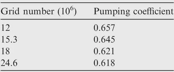
Table 2 Computed results of mixerejector pumping coefficient under different grid numbers.
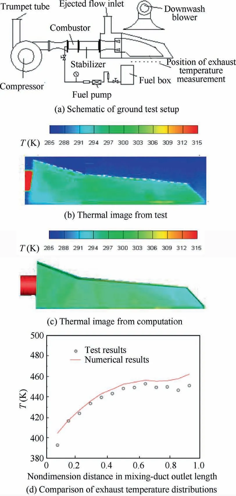
Fig.7 Validation of temperature distribution on IRS-integrating rear-fuselage test model.
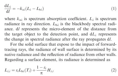
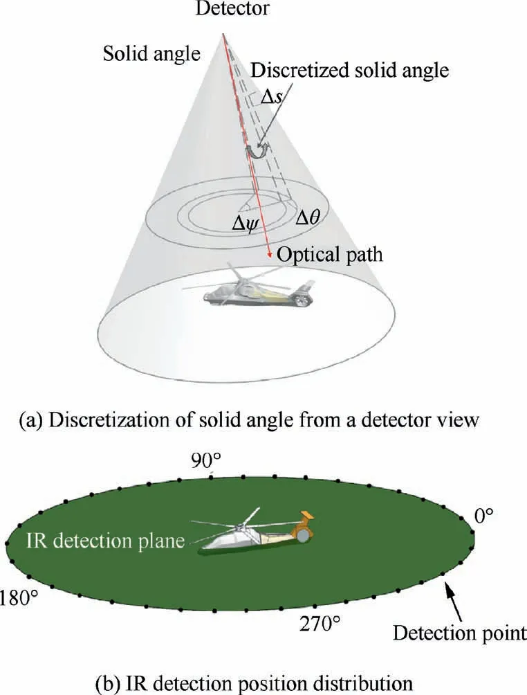
Fig. 8 Schematic diagram of infrared detection.
where the first term on the right side is the radiance of wall i by itself, and the Tis the temperature of the wall i. The second term is the reflected spectral radiance of wall i, Hrepresents the total illuminance received by the micro-element surface i.All of fuselage surfaces are treated as diffusive and grey. εis the emissivity.
In the backward process, every beam of energy emitted from target towards the detector is summed along optical path of the recorded rays. The whole ray transmission path is divided into n layers, with a segment thickness of Δs, to consider the absorption and emission effects in the radiation transfer route, such as
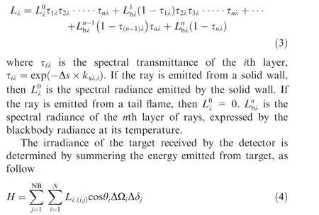
where NB is the total band number, N is the number of recorded rays, θis the angle between ray and the normal of wall i, ΔΩis the solid angle of i th ray, Δδis the spectrum interval.
Furthermore, assuming the target a point source, the radiant intensity of the target can be obtained as:

where Ris the distance between detector and helicopter.
The flight altitude of helicopter is generally at the maneuvering flight altitude (about 300 m). As the detection distance of IR detector can reach more than 10 km,therefore, as shown in Fig. 8(b), the position of the infrared detector on the ground and the detected helicopter are almost on the nearly same horizontal plane. Besides, as the main threats in the battlefield come from the ground-based IR detectors and IR-guided missiles, the infrared radiation distribution on the helicopter-located horizontal plane is concerned in current study.The detective points are distributed uniformly in the circumferential direction, with an interval angle of 10°.
4. Results and discussion
4.1. External flow field around helicopter
Four flight speeds are selected as specific research objects corresponding to the four flight states of the helicopter in turns.They are, V = 0 m/s that corresponds to the hovering state;V = 30 m/s that corresponds to a low-speed flight state,V=60 m/s that corresponds to a moderate-speed flight state;and V = 90 m/s corresponds to a high-speed flight state.
Fig.9 shows the streamlines of exhaust plume and external flow at different flight states of helicopter.Under the static state(that is, no downwash flow and no forward-flight flow, as displayed in Fig. 9(a), the exhaust flow development behaves as free jet. It mainly spreads downward in its narrow side of the large aspect slot. Under the hover state, as seen in Fig. 9(b),the development of exhaust plume is obviously affected upon the ‘‘pressing” role of rotor downwash. Apparently, the penetration length of exhaust plume along the backward direction is shortened with respect to the static state.Subjected to the tangential component of induced velocity of the rotor downwash,the streamlines of the exhaust flow from right-nozzle are not symmetrical to the left nozzle. Because of the clockwise rotation of the main rotor, the exhaust plume shows a ‘‘swirling”effect, in accordance with the main-rotor rotational direction.When compared to the hover status, under the forward-flight status, the exhaust flow is not only affected by the main-rotor downwash,but also affected by the forward-flight flow.As seen in Figs.9(c)–(e),the‘‘pressing”role of the rotor downwash on the exhaust plume flow is certainly weakened and the exhaust flow is forced to align with the forward-flight flow direction.When the backward flow (relative to the helicopter) passes through the helicopter body, it will form a low-pressure area behind the fuselage. The exhaust plume will be rolled into the low-pressure area when it reaches the back of the fuselage.Under the forward-flight state, the interaction between forward-flight flow and downwash flow makes the exhaust plume development more complicated, tightly dependent on the forward-flight speed.It can be seen from Fig.9(c)that when the helicopter is flying at low speed(V =30 m/s), the exhaust plume is entrained to the left side of fuselage due to the influence of tangential velocity of downwash flow.With the increase of helicopter flight speed,the role of the rotor downwash on the exhaust plume flow is significantly weakened and the exhaust flow is more seriously affected the forward-flight flow. As displayed in Figs.9(d)and(e),the exhaust flow is more align with the forward-flight flow direction. Also, the streamlines of the exhaust flow from right-nozzle are basically symmetrical to the left nozzle.

Fig. 9 Streamlines of exhaust plume and external flow.

Fig. 10 Streamlines and temperature contours of mixed flow on specified longitudinal sections.
Fig. 10 shows the temperature contours and flow chart of exhaust plume on several specified longitudinal sections under four flight conditions. It is seen from Fig. 10(a) the exhaust flow is mainly affected by the main-rotor downwash under the hover state. The exhaust plume is deflected to flow downward after it exhausts from the nozzle exit. When the flight speed is 30 m/s,it can be seen from Fig.10(b)that the exhaust plume ejecting from the right nozzle is blown to the left side of the fuselage after being discharged from the nozzle outlet. In this state, the exhaust plume is greatly affected by the rotor downwash induced velocity.When the flight speed increases to 60 m/s,as seen in Fig.10(c),the forward flow is stronger than the rotor downwash flow. The influencing role of downwash flow on the exhaust plume is consequently weakened. The exhaust plume is more seriously affected by the forward flow and forced to be consistent with the forward flow direction.The hot plume flow length on both sides of the fuselage becomes shorter. When the flight speed is further increased up to 90 m/s, as seen in Fig. 10(d), the exhaust flow is further affected by the forward flow, and the streamline distribution on both sides of the fuselage is nearly symmetrical.
4.2. Internal flow field inside IRS-integrating helicopter
Fig.11 and Fig.12 display the static pressure distribution and temperature distribution of the mixed flow inside the mixing duct on specific cross-sections, respectively. As the forwardflight speed changes, the flow field around the helicopter fuselage is altered,and subsequently the back-pressure at the outlet of mixing duct. As demonstrated in Fig. 11 and Fig. 12, the higher flight speed the lower the static pressure and the mixing-flow temperature in the mixing duct. As the mixing duct is highly curved,the higher forward-flight speed is conjectured to help modifying the plume injection and reducing the back-pressure at the outlet of mixing duct. In addition, the forward-flight also helps to enhance the pumping capacity of the mixer-ejector. Fig. 13 presents the influence of forwardflight speed on the ejection coefficient (φ=m/m, here mis the primary mass flow rate and min the secondary or entrained mass flow rate). It is confirmed that the ejection coefficient is generally increased with the increase of helicopter forward-flight speed. In particular the ejection coefficient of the left nozzle is a little greater than the right nozzle, except the forward-flight speed range from 20 m/s to 50 m/s.The reason is conjectured to be caused by the complicated interaction between forward-flight flow and the rotor-downwash flow.Fig. 14 presents the influence of forward-flight speed on the average temperature of mixed flow at the outlet of mixing duct.With the increase of helicopter forward-flight speed, the average exhaust temperature of mixing flow is reduced because of the increased ejection capacity.
Fig. 15 shows the velocity vectors and temperature contours inside the rear fuselage on several specified longitudinal sections.In general,the throughflow of the external flow inside the rear fuselage becomes stronger along the axial direction of helicopter. As schematically shown in Fig. 1(a) and Fig. 5(b),the X1 section is close to the rotor center so that the rotordownwash velocity is relative small.Under hover state,as seen in Fig. 15(a), due to the ‘‘swirling” effect of downwash flow,the inflow angle at the left intake is distinct from that at the right intake. Therefore, the throughflow of the external flow inside the rear fuselage is asymmetric. This feature remains clearly in the situation, when the forward-flight speed is relative small, as seen in Fig. 15(b). With the forward-flight speed is high (e.g., V = 60 m/s and 90 m/s), the role of downwash flow is weakened by the forward-flight flow, which makes the temperature distribution in the rear fuselage cavity tends to be symmetrical, as demonstrated in Figs. 15(c) and (d). Seen from Fig.15,it is also found that the temperature at the outer side of the mixing ducts or nearby the fuselage surfaces is less than that in the vicinity of symmetric plane inside the rear fuselage.
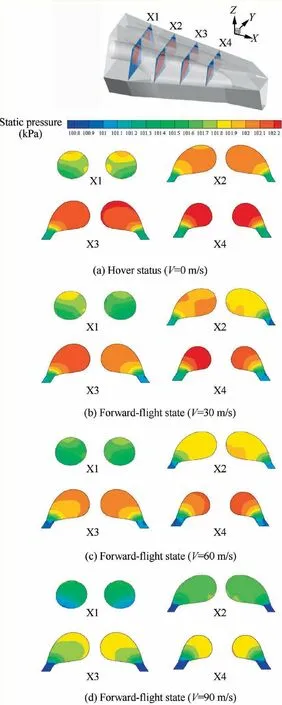
Fig. 11 Static pressure contours on longitudinal sections inside mixing duct.
Fig.16 presents the influence of forward-flight speed on the mass flow rates of the right and left intakes on the top of helicopter rear fuselage.Since the rotor rotates clockwise,the mass flow rate inflowing into the right intake is generally greater than the left intake under hover and low forward-speed situations.When the forward-flight speed is located in the range of 30–50 m/s,the mutual interaction between downwash flow and forward-flight flow causes an obvious reduction of inflow at the left intake but an increase at the right intake.
4.3. Temperature distribution of surfaces
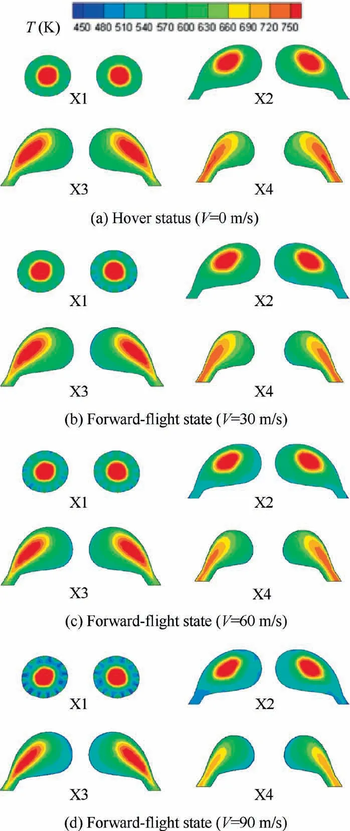
Fig. 12 Temperature contours on longitudinal sections inside mixing duct.
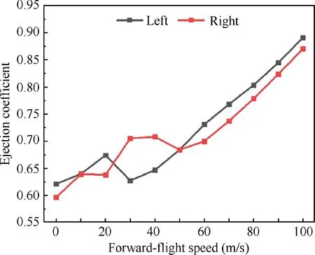
Fig. 13 Ejection coefficient varies with forward-flight speed.
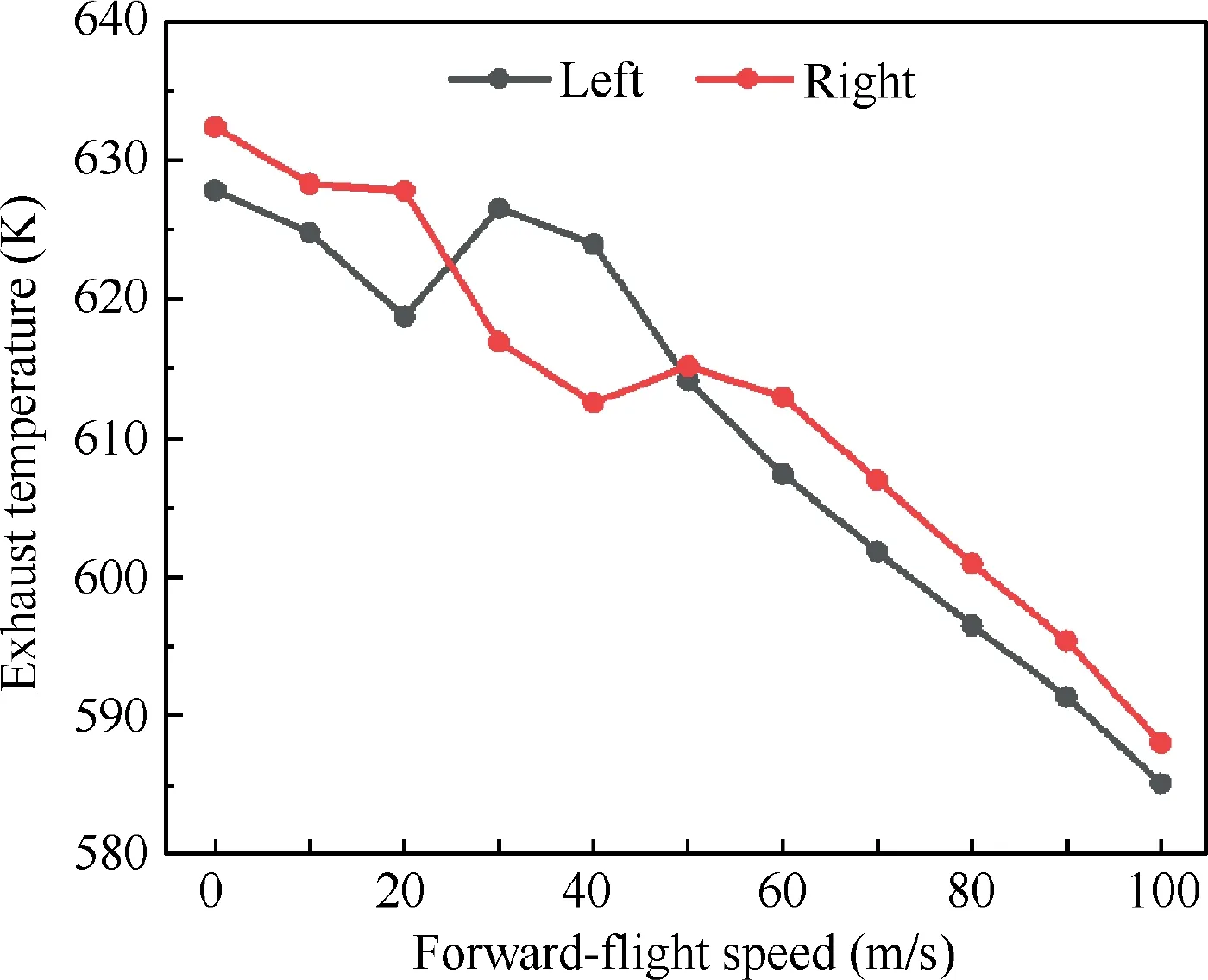
Fig. 14 Exhaust temperature varies with forward-flight speed.
Fig. 17 shows the wall temperature contours on the mixing duct surface. As previously illustrated in Fig. 13 and Fig. 16,when forward-flight speed is 30 m/s, the ejection flow rate of the left mixing duct and the mass flow rate of the left downwash flow intake are the minimum. Therefore, it is seen from Fig. 17 that the wall temperature on the left mixing duct surface is the highest when V = 30 m/s. It is suggested that the increase of forward-flight speed is not conducive to the downwash flow entering the rear fuselage cavity.However,when the forward-flight speed is high, the injection flow rate inside the mixing duct is enhanced obviously and the throughflow inside the rear fuselage is well modified,therefore,it can be seen from Fig.17 that the wall temperature on the mixing duct is the lowest when the helicopter forward-flight speed is 90 m/s.
Fig. 18 shows the temperature contours on the helicopter surface. It can be seen that when the forward-flight speed is 30 m/s, the wall temperature on the right-side surface of the helicopter is increased significantly. The main cause attributed to the impact of the mutual interaction between downwash flow and forward-flight flow.As the downwash flow has a tangential velocity component, the exhaust plume ejecting from the right outlet could be induced to move direct to the symmetric plane of helicopter. Under a hover state, the impact of downwash flow is dominant to ensure the exhaust plume with a strong downward penetration. Therefore, the deflection of the right-ejecting exhaust plume has a rare influence on the hot-flow interaction with the rear fuselage, as seen in Fig. 10(a). Under the forward-flight state that has a big speed, the forward-flight flow is strongly dominant to make the exhaust plume align with the forward-flight flow direction, as demonstrated in Fig. 10(d). However, when the forward-flight speed is about 30 m/s, the pressing role of downwash flow on the exhaust plume is a little reduced by the forward-flight flow.Meanwhile, the forward-flight flow does not have enough capacity to force the exhaust plume align with its direction.As a consequence, the exhaust plume ejecting from the right outlet is more concentrated around the right side of helicopter and possibly interacts with the helicopter rear fuselage,as seen in Fig. 10(b). From Fig. 18, it is also found that under the forward-flight state that has a big speed, the temperature distribution on the rear fuselage surface is modified when compared to the hover state. But in this situation, the surface of helicopter tail is partially heated by the hot flow due to the alignment of exhaust plume development with the forwardflight flow.
4.4. Infrared radiation intensity
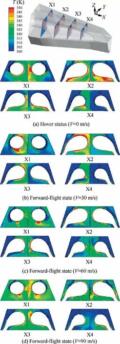
Fig. 15 Temperature contours on longitudinal sections inside rear fuselage.
Fig.19 shows the 3–5 μm infrared radiation intensity distribution of the helicopter on the detection plane in four flight states. In order to clearly analyze the contribution of each infrared radiation source, the gas radiation and fuselage surface radiation are separately displayed. With the increase of forward-flight speed, the peak infrared radiation intensity of the exhaust plume in 3–5 μm band is decreased by approximately 20% for every 30 m/s increase in the flight speed due to the reduction of exhaust temperature and the enhanced cooling effect of exhaust plume by the forward flying flow,as displayed in Fig. 19(a). With regard to the radiation from the fuselage surfaces, as shown in Fig. 19(b), when the flight speed is 30 m/s, the wall surface below the exhaust outlet on the right side of the fuselage is heated by the exhaust plume and the temperature rises obviously, resulting the peak infrared radiation intensity of the 3–5 μm band on the fuselage right-side at this speed is about 37% higher than the other three flight states.It can also be seen from Fig.19(b)that when the flight speed is 90 m/s,the infrared radiation intensity of the helicopter left-side surface is slightly higher than that of the other three flight states due to the heating effect of exhaust plume on the left-side surface. From the total infrared radiation intensity distribution, as shown in Fig. 19(c), the increasing of the flight speed is beneficial to reduce the infrared radiation intensity of the helicopter in 3–5 μm band, except that the infrared radiation on the right side of the helicopter under the situation when the flight speed is 30 m/s.In general,avoiding the heating effect of exhaust plume on fuselage surface is still the key to suppress the helicopter infrared radiation.
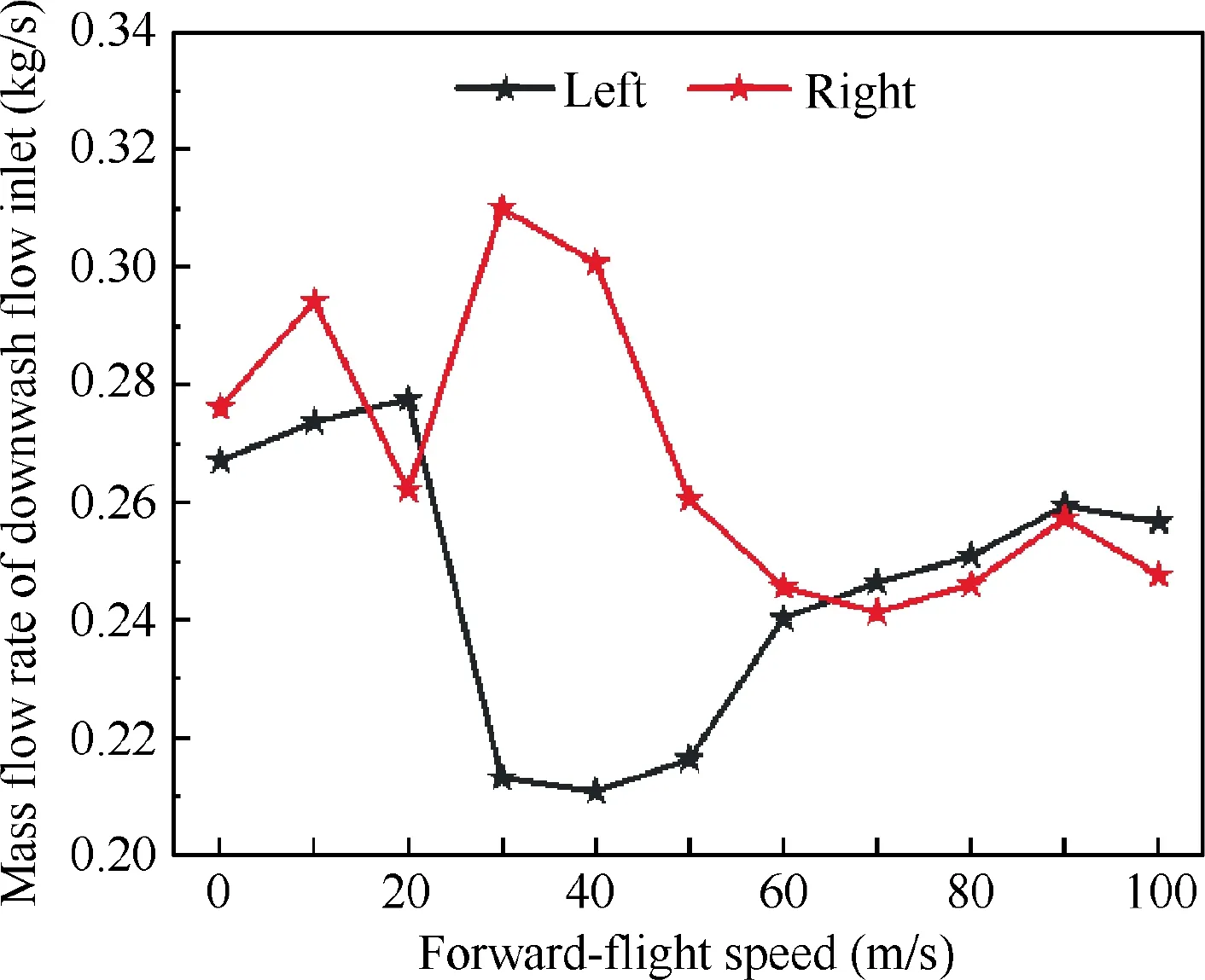
Fig. 16 Mass flow rate at intakes varies with forward-flight speed.
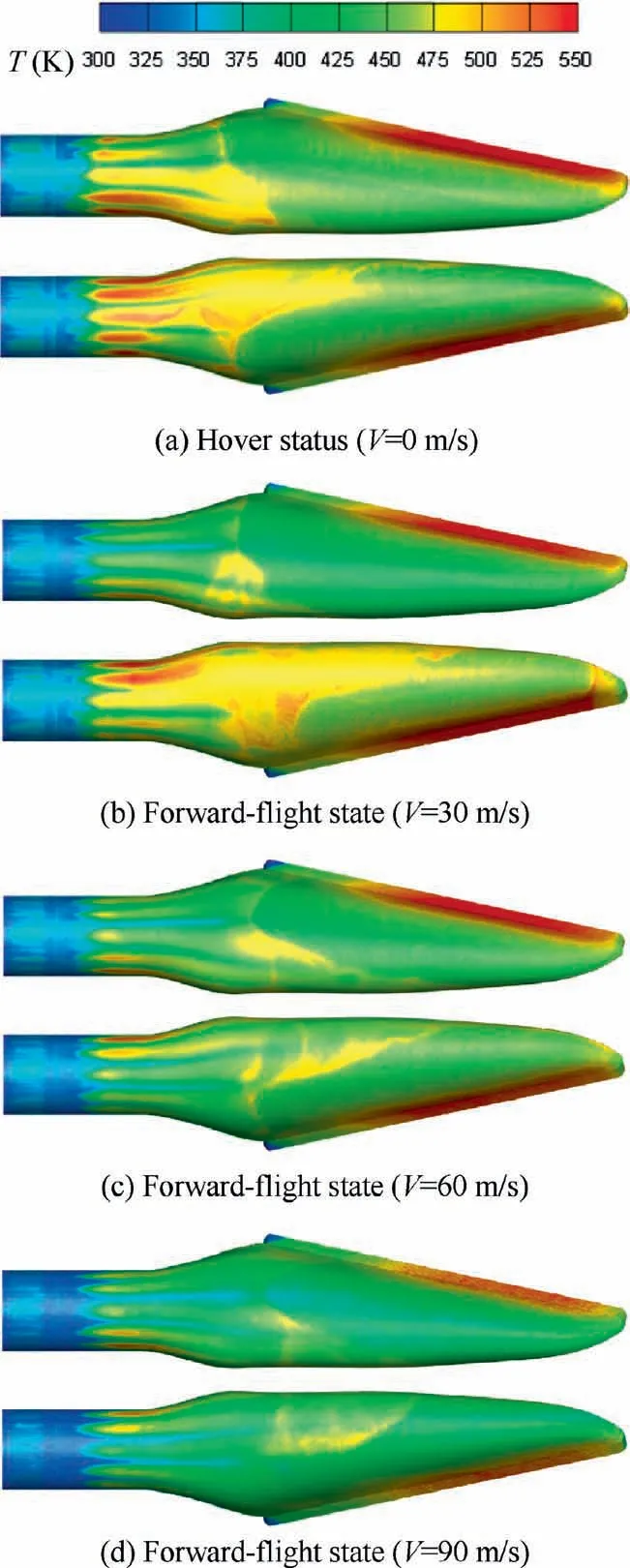
Fig. 17 Temperature distribution on mixing duct surface.

Fig. 18 Temperature distribution on helicopter surface.
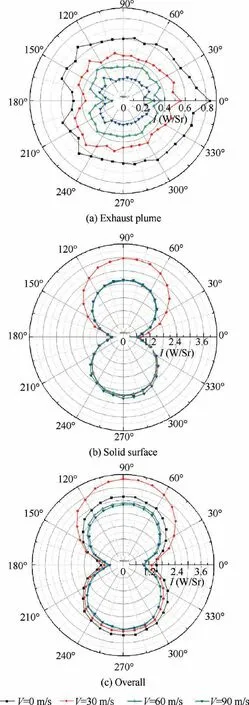
Fig. 19 3–5 μm band infrared radiation intensity distribution.
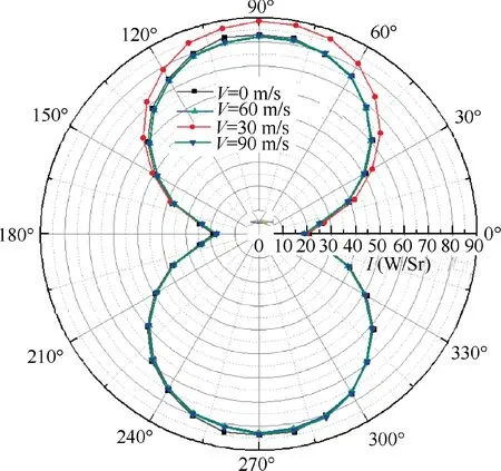
Fig. 20 8–14 μm band infrared radiation intensity distribution.
Fig. 20 shows the infrared radiation intensity distribution of helicopter in 8–14 μm band under four flight states on the detection plane. For the infrared radiation of 8–14 μm, the contribution of exhaust plume is very weak. It mainly comes from the surface of helicopter. The radiation intensity is related to the area and temperature of the airframe surface.When the flight speed is 30 m/s, the temperature on the local zone below the helicopter right exhaust outlet is heated by the exhaust plume, resulting in an increase of 8 W/Sr in the peak infrared radiation intensity of 8–14 μm band when compared with the other three states. Generally speaking, the forward-flight speed of helicopter has little effect on the infrared radiation of 8–14 μm band. Similar to the conclusion obtained in 3–5 μm band, avoiding the heating effect of exhaust plume on fuselage surface is still the key to reduce the infrared radiation intensity of helicopter in 8–14 μm band.
Fig. 21 shows the influence of forward-flight speed on the 3–5 μm infrared radiation intensity of exhaust plume. With the increase of forward-flight speed, the infrared radiation intensity of the exhaust plume in 3–5 μm band is decreased generally, because the exhaust plume is diluted more strongly.The infrared radiation intensity at 180° position is the lowest among the four detection positions.
However,the influence of forward-flight speed on the overall infrared radiation intensity of IRS-integrating helicopter is not monotonous, either in 3–5 μm band or 8–14 μm band, as displayed in Fig. 22. As the exhaust plume could be entrained to interact with the helicopter fuselage upon the impact of forward-flight flow, the infrared radiation from the helicopter fuselage would be enhanced.In current study,such a situation occurs when the flight speed is located in a range between 30 m/s and 40 m/s. By comparing, it is seen that the forward-flight speed of helicopter has little influence on the infrared radiation of 8–14 μm band.
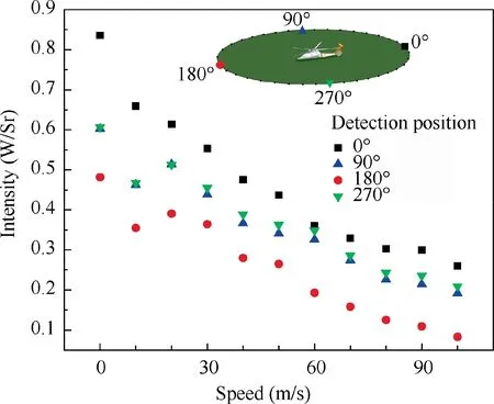
Fig. 21 Influence of forward-flight speed on 3–5 μm infrared radiation intensity of exhaust plume.
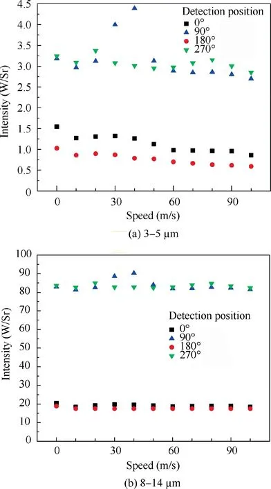
Fig. 22 Influence of forward-flight speed on overall infrared radiation intensity of helicopter.
5. Conclusions
The present study provides a numerical simulation to address the effects of forward-flight speed on exhaust plume flow and infrared radiation of the IRS-integrating helicopter, wherein the forward-flight speed is changed from 0 m/s (hover state)to 100 m/s, while both the engine exhaust parameters and the main-rotor operation parameters remains unchanged during different forward-flight velocities. From the current study,the following conclusions are put forward.
(1) Under the hover status, the development of exhaust plume is obviously affected upon the ‘pressing’ role of rotor downwash. In addition, because of the clockwise rotation of the main rotor, the exhaust plume shows a‘‘swirling” effect, in accordance with the main-rotor rotational direction.
(2) Under the forward-flight state, the interaction between forward-flight flow and downwash flow alters the exhaust plume development and the internal flow inside the IRS-integrating rear fuselage more complicatedly,tightly dependent on the forward-flight speed. Under a low-speed forward-flight state, the downwash flow is dominant in the external flowfield. Under a high-speed forward-flight state, the forward-flight flow is strongly dominant to make the exhaust plume align with the forward-flight flow direction. Of particular concern is the situation where the forward-flight flow has nearly the same level as the downwash flow, the hot mixing flow could possibly interacts with the helicopter rear fuselage to play a local heating effect.
(3) With the increase of forward-flight speed, the ejection coefficient is generally increased and the average exhaust temperature of mixing flow is decreased, leading to a reduction of the infrared radiation intensity of exhaust plume in 3–5 μm band. However, the influence of forward-flight speed on the overall infrared radiation intensity of IRS-integrating helicopter is conjectured not monotonous due to the complicated interaction between forward-flight flow and downwash flow.Under high-speed forward-flight states, the overall infrared radiation intensity of the IRS-integrating helicopter in 3–5 μm band is reduced with the increase of forwardflight speed. With respect to 3–5 μm band, the forward-flight speed has little effect on the infrared radiation in 8–14 μm band.
It is noted that in current study some simplified treatments are adopted to make the theoretical analysis on the current issue more realistic. In the actual practices, the complicated factors involved in real helicopter flight profile should be taken into consideration. This issue needs further concerns.
The authors declare that they have no known competing financial interests or personal relationships that could have appeared to influence the work reported in this paper.
The authors gratefully acknowledge the financial supports for this project from the National Science and Technology Major Project of China (No. J2019-III-0009-0053).
