
Feasibility study of creep feed grinding of 300M steel with zirconium corundum wheel
2022-03-25 04:28:12JiaqiangDANGHengZANGQinglongANWeiweiMINGMingCHEN
Chinese Journal of Aeronautics 2022年3期
Jiaqiang DANG, Heng ZANG, Qinglong AN,*, Weiwei MING,Ming CHEN
a School of Mechanical Engineering, Shanghai Jiao Tong University, Shanghai 200240, China
b State Key Laboratory of Mechanical Systems and Vibration, Shanghai Jiao Tong University, Shanghai 200240, China
KEYWORDS 300M steel;Chip formation;Creep feed grinding;Surface morphology;Zirconium corundum wheel
Abstract The ultrahigh strength 300M steel has been commonly used in the manufacture of aircraft landing gear and rotor shaft parts due to its excellent mechanical properties.Creep feed grinding is one of the essential operations during the whole component manufacturing processes.In this work, the feasibility of creep feed grinding of 300M steel by using the hard zirconium corundum wheel was theoretically and experimentally evaluated. A variety of responses including grinding forces, temperature fields, specific grinding energy, surface integrity and chip modes were carefully recorded. Besides, the mechanism of ground surface profile generation and the spatial frequency spectrum of the surface profile were tentatively analyzed. It was found that the wheel speed has a relative influence on the grinding forces and temperatures of which the work hardening effect dominates the material removal with lower wheel speed while the thermal softening becomes crucial as the wheel speed exceeds the critical value for the studied 300M steel. Furthermore, a scattered spatial frequency spectrum for the generated surface profile was noticed with lower wheel speed while the spectrum gathers towards the lower frequency values with higher amplitude as the wheel speed increases. The shearing chip and flowing chip dominates the main chip type, indicating the excellent abrasive sharpness during the grinding process. In general,the used zirconium corundum wheel presents feasibility for the creep feed grinding of 300M steel because of the high material removal rate, absence of surface burn, low wheel wear and higher compressive residual stresses.ⓒ2021 Chinese Society of Aeronautics and Astronautics.Production and hosting by Elsevier Ltd.This is an open access article under the CC BY-NC-ND license(http://creativecommons.org/licenses/by-nc-nd/4.0/).
1. Introduction
300M steel, characterized as a modified version of AISI 4340 steel, has superior mechanical properties of high tensile strength, yield strength and good fracture toughness.Its ultimate tensile strength could reach up to ~2000 MPa and yield strength could reach up to ~1700 MPa after being subjected to the proper heat treatment processes.Owing to such advan-
https://doi.org/10.1016/j.cja.2021.01.029
1000-9361 ⓒ2021 Chinese Society of Aeronautics and Astronautics. Production and hosting by Elsevier Ltd.
This is an open access article under the CC BY-NC-ND license(http://creativecommons.org/licenses/by-nc-nd/4.0/).tages, ultrahigh strength 300M steel has been commonly applied in the production of aircraft landing gear and rotor shaft parts, which are served in the harsh environment.However, 300M steel has been unfortunately regarded as a typical difficult-to-machine material by manufacturers due to its relatively high strength,high hardness and poor ductility.
Many researchers have paid attention to the high-efficiency machining of ultrahigh strength 300M steels and diverse aspects including cutting tool design,parameters optimizationand novel lubrication methodology explorationwere covered in the research processes. Wang and Zhaoattempted optimizing the novel ceramic tool materials for cutting 300M steel by analytic hierarchy process in combination with Criteria Importance Through Intercriteria Correlation methods.They finally obtained the optimization results of mechanical properties for the ceramic tool and the process performance as well as tool wear mechanisms were subsequently investigated.Sadeghifar et al.investigated the optimization strategy by a hybrid genetic algorithm to identify the optimal process parameters to improve the machining characteristics and residual stresses during orthogonal turning of 300M steel. They concluded that the weighting factors show a higher influence on the optimal values of the objective function than the given process parameters. Ajaja et al.focused on the machining condition optimization to weaken the machined surface roughness and white layer thickness, enhance the compressive surface residual stresses when hard turning the 300M steel with a bulk hardness of 55 HRC via principal component analysis(PCA) and gray relational analysis (GRA) methods. It was noted that the combination of PCA and GRA approach was responsible for reducing the surface roughness, white layer thickness while increasing the compressive axial and tangential surface residual stresses. Zhang et al.addressed the influence of machining parameters on the cutting responses during highspeed milling the 300M steel with dry and cryogenic minimum quantity lubrication(CMQL)conditions.The findings showed that the CMQL approach could lower the cutting forces and temperatures, in which the cutting depth and speed have the most significant influence on the cutting force and temperature, respectively. Note that most studies regarding the 300M steel machining are focused on the cutting methodology in order to optimize the responses induced by the processing.However, few types of research are collected to give guidance for the grinding performance evaluation of 300M steel which is crucial to be well known for the manufacturers during the production engineering applications since grinding-induced surface properties play an essential role in the final fatigue life of the components.
To be specific, grinding is one of the key finish machining operations for the production of most aerospace and automobile parts.The single grain grinding was firstly developed at the nanoscale depth of cut to study the fundamental material removal mechanismand the maximum undeformed chip thickness was then obtained.High dimensional accuracy and required surface integrity are collectively demanded outputs of this process.A lot of researchers have put effort into the grinding characteristics of difficult-to-cut materials, in which three categories including surface grinding,speed stroke grindingand creep feed grindingare involved.Manimaran and Kumarinvestigated the surface grinding performance of EN31 steel with seeded-gel abrasive (SG)grinding wheel under liquid nitrogen(LN2)cryogenic method.They found that the delivery pressure of coolant and grinding wheel type have great influence on the grinding forces and surface roughness, both of which were reduced under cryogenic environment compared to dry and wet grinding. Duscha et al.discussed the distribution of residual stress originating from the practical speed stroke grinding experiments of steels with cubic boron nitride (CBN) grinding wheel. The thermal aspects of speed stroke grinding given an in-development FEA model were also studied.Xi et al.evaluated the performance when creep feed grinding the Ti-Al alloy by using the electroplated diamond and CBN grinding wheels. The grinding responses such as wheel wear, material removal rate, surface integrity as well as chip type are discussed with the variation of operating parameters. They found that the diamond wheel is responsible for favorable grinding outcomes given better material removal rate but slighter wheel wear rate.Apart from the SG,diamond and CBN wheels,the zirconium corundum(ZA)and brown fused alumina(BA)abrasive wheels were also utilized to creep feed grind the difficult-to-cut materials, especially for the high strength steels. In this way,the grinding process was enhanced while the total grinding cost was reduced due to the wheel cost saving. Wang et al.studied the influences of abrasive material (ZA and BA) and hardness on the machining efficiency and wear type of grinding wheels subjected to rail grinding experiments. They draw the conclusions that ZA wheel contributes to higher grinding efficiency while lower degree of surface burn risk, thinner white layer and weaker tensile residual stresses compared to BA wheel. Meanwhile, the surface roughness shows downtrend while thickness of white layer increases as the wheel hardness was elevated. In their another work,the removal mechanism of rail material during the grinding process with different forward speeds was concerned. It was found that the grinding efficiency increase first and then decreases while the machined surface quality is improved with the elevation of forward speed.
It can be drawn from the literature survey that,most previous studies on the 300M steel were focused on the material characterization, high-efficiency cutting and surface strengthening. However, researches on grinding characteristics of 300M steel are still rare, especially for the creep feed grinding process,which greatly limits the development of 300M steel in both academic and engineering aspects.Meanwhile,due to the high hardness and work hardening tendency,grinding of 300M steel still faces several challenges but its grindability is of great importance to be understood by industrial manufacturers. To cover this gap and promote the engineering application, the present work was conducted to comprehensively evaluate the performance of creep grinding of 300M steel.The ZA grinding wheel was used for the experiments owing to its superior creep resistance during the grinding process.The grinding forces and temperature fields under different input parameters were carefully recorded.The grinding induced surface features including surface topography and surface roughness were discussed in detail. Besides, the surface profiles under different parameters were analyzed with spatial frequency spectrum to gain more in-depth understanding about the creep feed grinding. This paper is expected to provide technical guidance to those developing high-efficiency grinding technology of 300M steel applied to engineering applications.
2. Experimental procedures
The workpiece material tested in the present work was 300M(40CrNi2Si2MoVA) ultrahigh strength steel manufactured with 575°F (302°C) temper method. The chemical compositions(wt%)of the studied material is 0.42%carbon,1.65%silicon, 0.07% vanadium, 0.80% chromium, 0.75% manganese,1.80% nickel, 0.40% molybdenum and the balance of iron.The tensile strength and yield strength at room temperature of 300M steel used in the experiments are 2013 MPa and 1696 MPa, respectively, which were provided by the material manufacturers of LATROBE specialty steel company. In this study, the tested material was machined into cuboid-shaped specimens with a size of 30(L)×20(W)×15(H)mmby wire electrical discharge machining (WEDM) method for grinding tests. Before the machining experiments, the metallographic specimen was prepared by a serial of operations including hot mounting, mechanical polishing with silicon carbide(SiC) sandpapers (180#, 360#, 800#, 1200#) and a diamond suspension (9 μm, 3 μm and 50 nm). After that, the samples were finally etched by 4% Nital for optical microscope (OM)and scanning electron microscope (SEM) observations and meanwhile used for vibration polishing with a SiOsuspension(30 nm) for electron backscattered diffraction (EBSD) analysis, respectively. Fig. 1(a)–(d) shows the microstructure of 300M steel used in the present work with OM, SEM, grain boundary of EBSD and the enlarged SEM images, respectively.It has been found that the tempered martensite and bainite dominates the microstructure of 300M steel and they present typical lath features concerning the grain boundary maps.
All the grinding trials were carried out on an MKL 7132 surface grinding machine in the up-grinding mode.Fig.2 plots the schematic diagram of the setup for grinding experiments and data acquisition. During the processing, the tangential and normal grinding forces were recorded by a piezoceramic dynamometer (Kistler 9272) in connection with a charge amplifier (Kistler 5070A). The temperature fields induced by the grinding process were captured by the infrared thermal imager (FLIR A615) with a space resolution of 0.68 mrad.Both of force and temperature signals can be collected by its individual software installed on the PC. Fig. 3 shows the insitu experimental setup and zirconium corundum grinding wheel for performing the grinding experiments. The grinding wheel of zirconium corundum abrasives provided by the Norton company was used, which has a constituent of AlOand ZrO, diameter of 400 mm, width of 50 mm and abrasive particle size of 60#.The experimental grinding parameters used in the present study are listed in Table 1.It should be noted that the process parameters and their level of the present work were selected based on the practical production of components suggested by the manufacturers. Each of the trials was repeated three times and the average value of the collected data was used for the final analysis. After each trial, the grinding wheel was trimmed by the diamond wheel dresser to keep the abrasive sharp with a rough and finish dressing speed of 600 mm/min and 200 mm/min, respectively.

Fig. 1 Microstructures of 300M steel prior to creep feed grinding process.

Fig. 2 Schematic diagram of setup for grinding experiments and data acquisition.
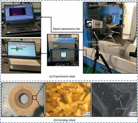
Fig. 3 In-situ experimental setup and grinding wheel for grinding experiments.
After the completion of all the grinding experiments, the specific grinding energy versus the input parameters was calculated to evaluate the energy consumption evolution for varying wheel speeds.The machined surface topography was observed by OM (Keyence VHX-500F) and a laser scanning confocal microscope (Zeiss LSM800) while the surface roughness was measured by a commercial portable instrument (Mitutoyo SJ-210). The chip morphology and microstructure alternation of the machined superficial layer were captured by SEM(Vega LaB6) under the secondary electron mode. The surface residual stresses of two orthogonal directions (σ: parallel to the direction of grinding feed along the x-axis, σ: perpendicular to the grinding direction along the y-axis) were measured by an X-ray stresses analyzer with Cr-Kα radiation using a voltage of 20 kV,current of 4 mA and X-ray incident angle of 35°.
3. Results and discussion
3.1. Grinding force description
The grinding force plays an essential role in all of the grinding responses since it indicates prognosis on the process stability,quality and some other machining-induced defects.During the grinding process, the in-situ force signals marked as horizontal force (F), axial force (F) and vertical force (F) werecarefully recorded by the Kistler dynamometer. The original forces generated with wheel speed of 10 m/s, feed rate of 200 mm/min and grinding depth of 0.2 mm is plotted in Fig.4(a),with the steady state(see the red rectangular region)enlarged shown in Fig. 4(b). It is clear that the original forces are composed of three stages namely cut-in, steady state and cut-off,and all of the generated forces in the three orthogonal directions present a high frequency feature due to the timevarying interactions between workpiece material and numerous abrasive grains. More interestingly, the force signals of both Fand Fin the steady state indicate periodic evolution with the workpiece forward. To be specific, this phenomenon can be attributed to the regular variation of the undeformed chip thickness during one pass cycle grinding. Meanwhile, it can be noted that the force components of Fand Fkeep consistent periodicity because of their magnitude variation,which matches well with the analysis on undeformed chip thickness.During the grinding process with applied grinding wheel, the grinding force was actually the superposition of numerous single grits.For the single grit,it will undergo three stages including sliding, ploughing and cutting during one pass cycle. In general, the force signal shows larger magnitude as the undeformed chip thickness of single grit was elevated during the grinding process.
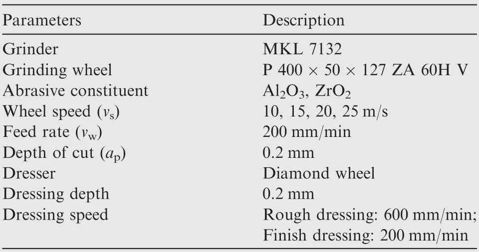
Table 1 Grinding parameters used in present work.
According to the force signals generated in the steady state,the average horizontal and vertical forces under different input grinding parameters were then calculated by using the Eq.(1):
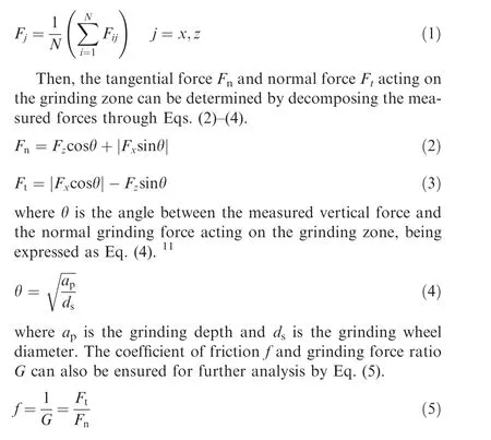
Fig. 5 is the comprehensive plot with respect to the steady grinding forces including coefficient of friction, force components and force ratio under different process parameters.Each of the measurement was repeated three times to obtain the reliable results for further analysis. As depicted in Fig. 5(a), the coefficient of friction presents a dropping tendency with the elevation of wheel speed. This finding can be mainly ascribed to the different contact conditions (shearing or ploughing dominates the material removal) between the abrasive wheel and workpiece with varying wheel speeds.It can be noted from Fig.5(b)that both Fand Ffirst increased and then decreased with the wheel speed increased from 10 m/s to 25 m/s.Theoretically,the grinding force decreased with the elevation of wheel speed due to the reduction of undeformed chip thickness of the single abrasive grain.However,due to the liable work hardening effect of the studied 300M steel (measured ground surface hardness of about 590,575,563,530 HV with wheel speeds of 25,20,15,10 m/s and the matrix of about 500 HV),the grinding force initially increased as the wheel speed became higher within a certain range. Moreover, it can be seen that for the creep feed grinding of ultrahigh strength steel, the normal grinding force is relatively higher than the tangential force,especially for the case with higher wheel speed during the grinding process. This phenomenon contributes directly to the increase of grinding force ratio with the increment of wheel speed, which turns to be more obvious with higher magnitude of wheel speed.
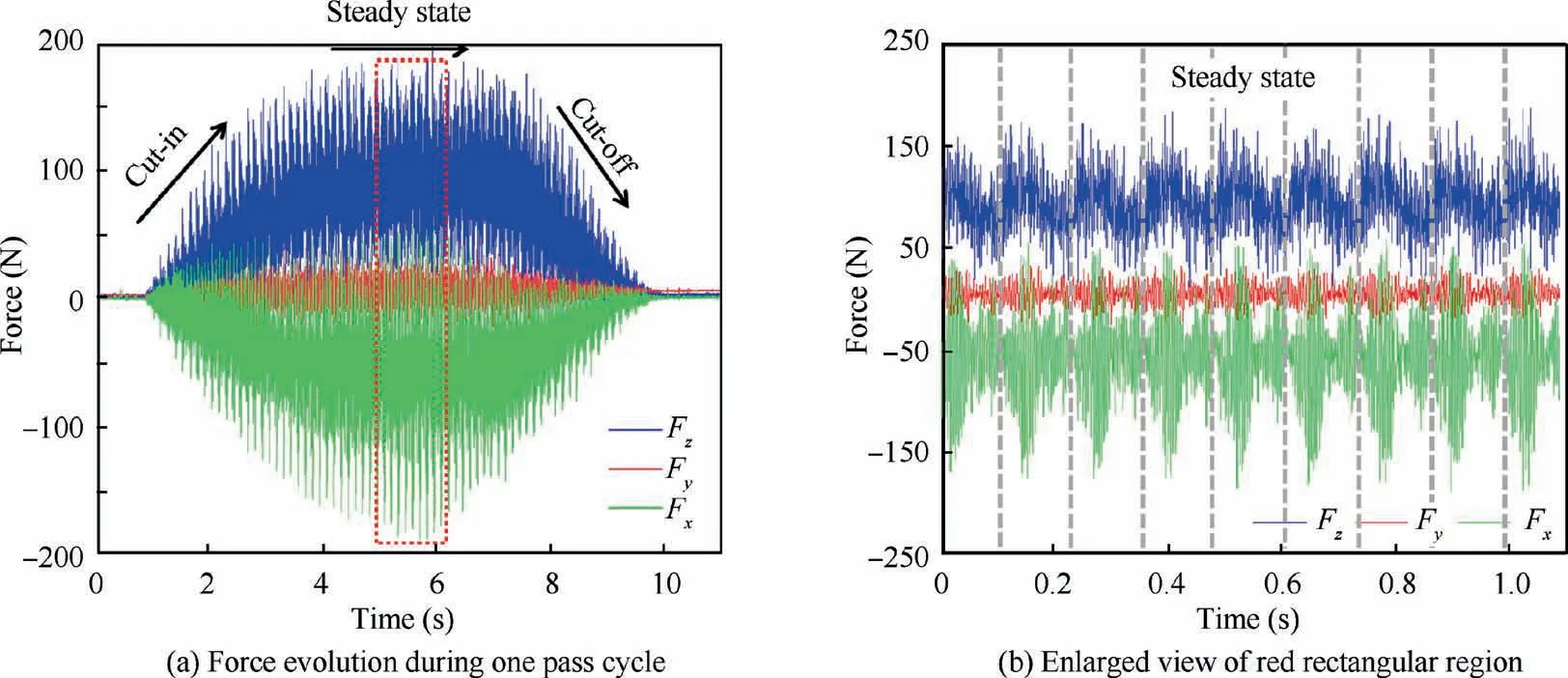
Fig. 4 In-situ force signals with wheel speed of 10 m/s.
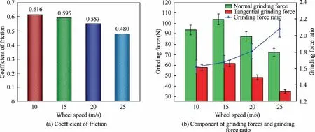
Fig. 5 Results under different wheel speeds for grinding experiments.
3.2. Grinding temperature field
The grinding temperature field was also tested based on the thermal infrared imager with the arranged parameters which was also used by Liu et al.and the maximum temperature of the grinding zone was extracted and plotted according to its corresponding field, as shown in Fig. 6. It is clear that the grinding temperature continues to rise in the beginning of processing, approaches to the peak magnitude at some point due to the accumulation of heat, and then drops with the wheel advancement. The higher wheel speed usually leads to the increase of grinding temperatures due to the elevation of number of abrasive grains involved in the grinding process.Nevertheless, the temperature magnitude overall presents lower values for the investigated steel compared with the results in the recent published reports,which shows the unique advantages of zirconium corundum wheel for creep feed grinding of the 300M steel to reduce surface burn.
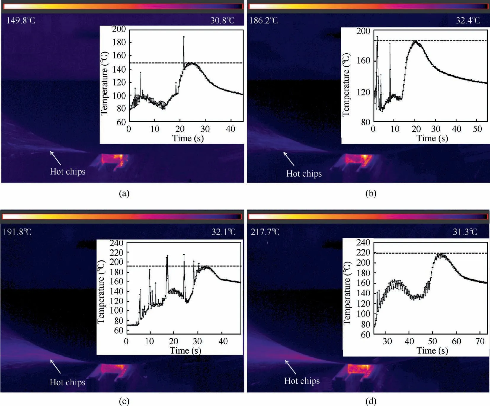
Fig. 6 Grinding temperature field under different wheel speeds.
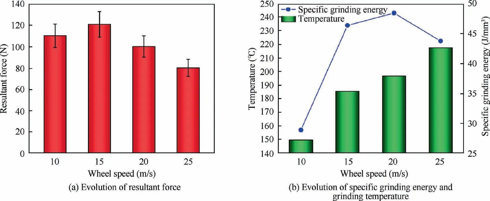
Fig. 7 Influence of wheel speeds on machining responses.
The specific grinding energy can reflect the energy consumption during unit volume of material removal process and thereby determines the process performance, which can be expressed by Eq. (6).

where Pis the grinding power, vis the wheel speed, vis the workpiece feed rate,Fis the tangential grinding force,bis the workpiece width and ais the grinding depth.According to the force results and arranged parameters, the specific grinding energy under different wheel speeds was calculated and it was correlated with the resultant grinding forces and temperatures,as shown in Fig.7.It can be seen from Fig.7(a)that the resultant grinding force shows similar evolution tendency with the force component, which first increases and then decreases as the wheel speed increases while the temperature shows a continuous uptrend. Interestingly, it can be seen from Fig. 7(b) that the specific grinding energy also increases first and then decreases, approaching the maximum value under wheel speed of 20 m/s. This finding can be mainly attributed to the competition between the work hardening and thermal softening. During the grinding process, the mechanical deformation of superficial material occurred under the strong force induced by the numerous abrasive grits. As a result, dislocation propagation,tangle and then dislocation cell (i.e.grain refinement)were generated, which inevitably causes the work hardening according to the classic Hall-Petch effect. Meanwhile, dislocation annihilation also appeared on the deformation layer due to the associated recovery and recrystallization under high temperatures,which leads to thermal softening to some extent.In other words, the final properties of the surface layer were determined by the combination of those phenomena. In this paper, it was found that the work hardening effect dominates the material removal with lower wheel speed while the thermal softening becomes crucial as the wheel speed exceeds the critical value for the studied 300M steel, which can be verified by the shown results.
3.3. Surface roughness characterization and morphology discussion
The surface roughness is usually utilized to characterize the machined surface quality and plays an important role in determining the final service life of shaped components.Fig. 8 presents the average value of surface roughness(each parameter was tested three times)under different wheel speeds. It can be found that the surface roughness indicates elevation trend with the increase of wheel speed. This can be mainly ascribed to the adhesive wear of grinding wheel due to the high grinding temperatures with increased wheel speed, which was also reported by Zhang et al.Meanwhile, due to the inherent higher grit size of grinding wheel and depth of cut for the creep feed grinding process, the magnitude of surface roughness is relatively higher compared to the finish grinding operation.The in-depth understanding of the mechanism involved in the generation of surface profile during the grinding process and thereby the final surface roughness magnitude will be discussed later.
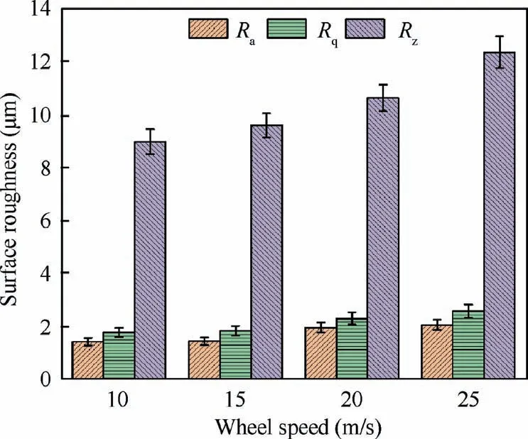
Fig.8 Surface roughness evolution under different wheel speeds.

Fig. 9 Ground surface profile under different wheel speeds.
During the grinding process, the surface profile was produced by the interaction between numerous abrasive grits and workpiece. Theoretically, the final profile of the ground surface can be approximated by the lowest points of the abrasive trajectory and the values of surface roughness then can be calculated.Assuming that there are totally Nc rows of abrasives distributed along the circumferential direction and constant distance between adjacent rows was determined.Besides, there are Nm abrasive grits passing through the cross-sectional surface (Y-direction) and the distance between adjacent abrasives is also constant.Both the abrasive tip radius and protrusion height are assumed to follow a normal function, which can be expressed as Eqs. (7) and (8).
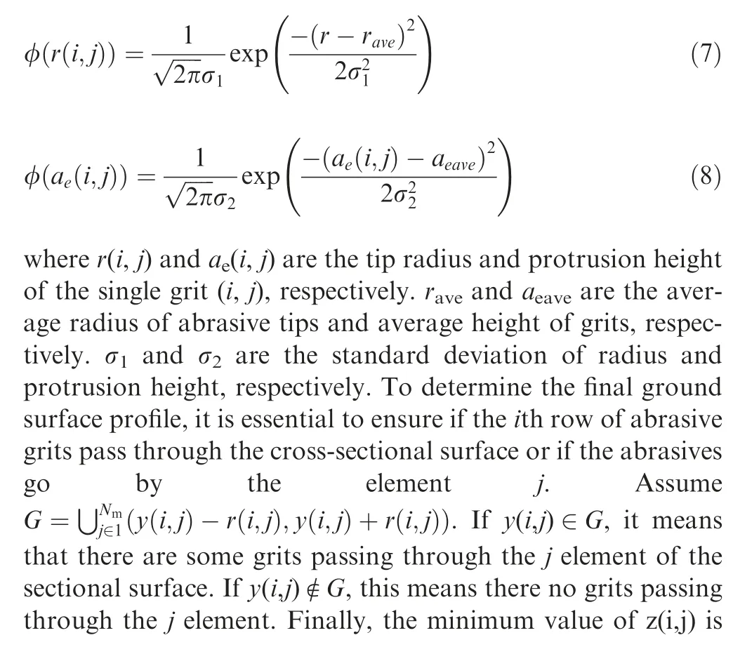

Fig. 9 shows the ground surface profiles under different wheel speeds detected by the laser scanning confocal microscope. It can be clearly found that the grinding marks due to the cutting traces of numerous abrasive grains were generated on the ground surface regardless of the wheel speed.This phenomenon is the inherent outcome of grinding process determined by the wheel property such as abrasive material, size and binding type. Meanwhile, grooves and chip adhesion due to the material side flow were observed. As can be seen from the surface profiles shown in the right side,some irregular cusps were captured on the surface profile, especially with higher wheel speed. In order to analyze the mechanism for the surface generation, the spatial frequency spectrum for the surface profiles was tentatively conducted in this paper and the results are plotted in Fig. 10.
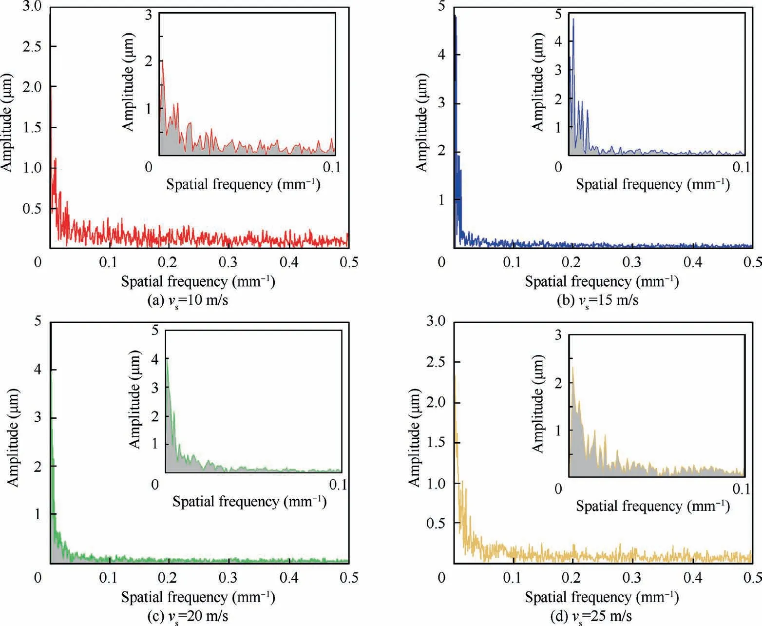
Fig. 10 Spatial frequency analysis of ground surface profile with different wheel speeds.
Fig. 10(a)–(d) represents the frequency spectrum results of generated surface profiles under different wheel speeds, with the curves of low frequency region enlarged as shown in the top right corner. It is obvious that the frequency shows random distribution and covers all of the tested regions regardless of the grinding parameters, which is totally different with the results of milling process.When the lower wheel speed of 10 m/s was adopted, the frequency points of the tested profile are more scattered (see Fig. 10(a)), which means the profile is the superposition of many traces with different frequencies.In other words, this finding may be supported by the increased number of abrasive grits passing through the cross-sectional surface. Nevertheless, the enlarged view of low frequency region shows that the amplitudes indicate relatively lower values,implying a lower surface roughness for the profile. As the wheel speed increases(see 15 m/s and 20 m/s),the corresponding frequency points of surface profile gather toward the lower values (see Fig. 10(b) and (c)). This behavior illustrates an information that the number of abrasive grits passing through the cross-sectional surface for the generation of surface profile reduced.Meanwhile,it can also be supported by the reduction of undeformed chip thickness with the elevation of wheel speed. However, the amplitudes corresponding to the lower frequency region greatly increased, which implies the increase of average surface roughness. As the wheel speed continues to increase, the number of low-frequency points with higher amplitudes is enhanced, being supported by the reduction of number of abrasive grits passing through the cross-sectional surface. Meanwhile, some higher frequency points were also captured owing to the material side flow behavior induced by the high temperatures.
Fig. 11 shows the representative SEM images of ground surface under different wheel speeds, which accords well with the analysis of surface roughness and spatial frequency spectrum. During grinding with lower wheel speed, relatively smooth surface was produced while surface smearing and chip adhesion gradually occurred on the ground surface with the elevation of wheel speed. Furthermore, severe material side flow appeared on the surface with the wheel speed of 25 m/s,which sharply increases the average value of roughness and deteriorates the ground surface quality. Fig. 12 plots the elemental mapping distribution of ground surface with wheel speed of 25 m/s.Note that due to the severe material side flow induced by the high grinding temperatures, some alloying elements were slightly and regionally dissipated on the ground surface. Furthermore, the carbon element partially gathered on the machined surface due to the smearing effect induced by the high temperatures. More importantly, it can be clearly found that surface burn was absent in all of the tested cases.
3.4. Microstructure alternation and residual stresses

Fig. 11 SEM images of representative ground surface under different wheel speeds.
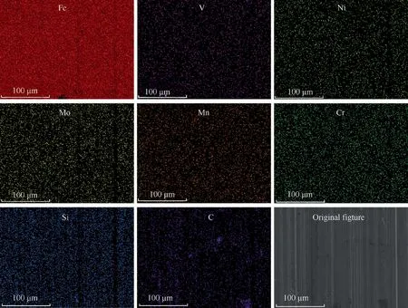
Fig. 12 Elemental mapping distribution of ground surface with wheel speed of 25 m/s.
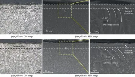
Fig. 13 Optical and SEM images of microstructure alternation of the surface layer under different wheel speeds.
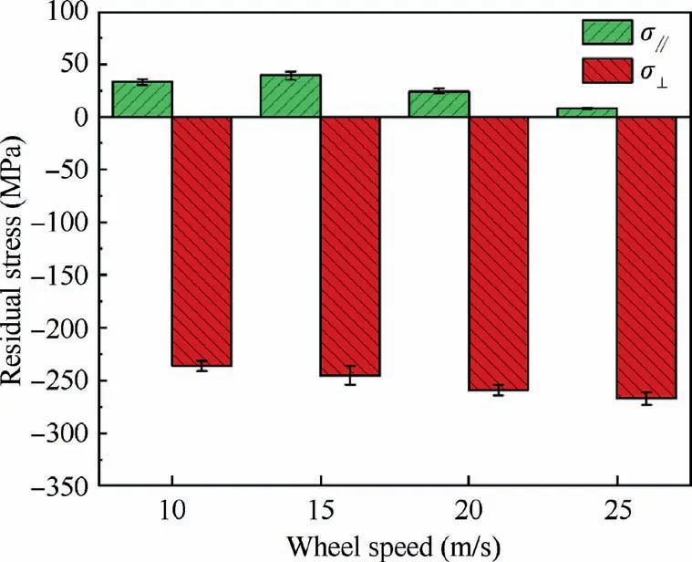
Fig. 14 Residual stress of ground surface with different wheel speeds.
As can be obtained from the analysis of surface morphology,no obvious signs showing the surface burn even at the high wheel speed of 25 m/s were observed. This partially shows the feasibility and reliability of the zirconium corundum wheel for the creep feed grinding process of the ultrahigh strength 300M steel. This section will discuss the microstructure alternation and surface residual stresses induced by the creep feed grinding process for comprehensively evaluating the creep feed grinding performance. Fig. 13 plots the OM and SEM images of surface microstructure alternation with different wheel speeds.It can be seen from the OM images that a surface plastic deformation (SPD) layer was observed on the region adjacent to the machined surface for both wheel speeds. From the magnified view of SEM images, the deformed lamella was noticed and meanwhile the grains within a thin layer of~2 μm were severely refined in view of its morphology.Besides, a higher wheel speed contributes to the increase of deformation (see the defined angle θ between the deformed lamella and surface) due to the elevation of strain rate during the grinding process.Fig.14 shows the surface residual stresses induced by the creep grinding. Interestingly, all of the surface residual stresses present compressive values in the perpendicular direction but tensile values in the parallel direction.Moreover, the compressive stress increases while tensile stress reduces with the increase of wheel speed, which shows the potential of this grinding process applied in the shaped parts to improve their fatigue resistance during the service process.
3.5. Chip morphology
Chip formation during grinding process is the direct signs reflecting the workpiece properties and process performance.Fig. 15 plots the representative SEM images of chip modes during creep feed grinding of 300M steel. It can be clearly found that the shearing chip and flowing chip dominate the main chip type, which outlines excellent abrasive sharpness during grinding process. This finding is similar to the results during grinding the 100Cr6 steel.Meanwhile, the shearing chip presents typical serrated and smooth features on the free and back surfaces,respectively.The free surface occupies some fractured edges due to the diverse geometry of the abrasive edges. The comparison of chip morphology with different wheel speeds is also presented in Fig.16.It can be clearly noted that the chip indicates break and thick features under lower wheel speed while it gradually evolves into continuous and thin chips with the elevation of wheel speed.All in all,the used zirconium corundum wheel presents feasibility for the creep feed grinding of 300M steel concerning the machining responses of high material removal rate,absence of surface burn,low wheel wear, higher compressive residual stresses and favorable chip removal process.

Fig. 15 SEM images of typical chip morphology with wheel speed of 25 m/s.
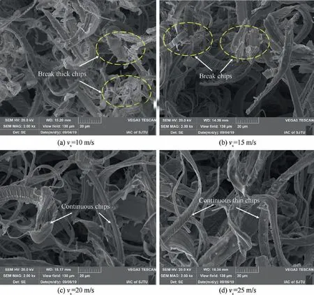
Fig. 16 Comparison of chip morphology with different wheel speeds.
4. Conclusions
Feasibility of creep feed grinding of an ultrahigh strength 300M steel by using the zirconium corundum wheel was evaluated in this paper. A variety of topics including grinding forces, temperature fields, ground surface integrity and chip morphology are addressed. Based on the findings, the main conclusions are summarized as follows.
(1) The zirconium corundum grinding wheel shows good feasibility for the creep feed grinding of 300M steel in view of the high material removal rate, low grinding forces, absence of surface burn, low wheel clogging and high compressive residual stresses.
(2) There is a competition between the work hardening and thermal softening effect during the creep grinding process. The work hardening effect dominates the material removal with lower wheel speed while the thermal softening becomes crucial as the wheel speed exceeds the critical value for the studied 300M steel.
(3) The lower wheel speed during creep feed grinding process usually leads to a scattered spatial frequency spectrum for the generated surface profile. Nevertheless,the spectrum gathers towards the lower frequency values with higher amplitude as the wheel speed increases.
(4) Shearing chip and flowing chip were found to be the main chip modes,which indicates that the poor ductility of 300M steel may not arise much concern for the manufacturers during creep feed grinding. Meanwhile, it is still possible to elevate the material removal rate within the surface burn limit to achieve high efficiency grinding of this material.
The authors declare that they have no known competing financial interests or personal relationships that could have appeared to influence the work reported in this paper.
This study was supported by the National Natural Science Foundation of China (U19372708).
Supplementary data to this article can be found online at https://doi.org/10.1016/j.cja.2021.01.029.