Microstructural evolution and mechanical properties of brazed IN718 ultrathin-walled capillary structure using different particulate reinforced filler alloy
Wenpeng HAN, Min WAN, Rui ZHAO, Hui KANG, Yuantong RAO
School of Mechanical Engineering and Automation, Beihang University, Beijing 100191, China
KEYWORDS Composite filler alloy;Hypersonic Precooler;Mechanical properties;Ultrathin-walled structure;Vacuum brazing
Abstract The development of hypersonic precooled combined cycle engine provides a reliable power system for the future intercontinental navigation and reusable space orbital transportation.The compact heat exchanger precooler is the key component of the cooling cycle system,which provides efficient heat management for the hypersonic engine.This investigation mainly focused on the manufacturing process of precooler,and the typical structure of the precooler,ultrathin-walled capillary structure, was facilitated by the vacuum brazing using the particle reinforced composite filler alloy. The effects of different types and contents of the reinforced particle on the spreading behaviour,microstructural evolution,mechanical performance changes were investigated in detail.During the cooling process, the nucleation and growth of the γ-Ni solid solution on the surface of the reinforced particles was the main reason for the microstructure homogenization. Compared to the Ni particles, the more obvious mechanical properties improvement could be achieved by using IN718 particles reinforced composite filler alloy. The tensile strength and elongation of the brazed ultrathin-walled structure present 9.36% and 47.27% higher than that using initial filler alloy.Moreover, the micro-hardness distribution result revealed that the reinforced particles reduced the overall micro-hardness of the brazed region, dispersed the eutectic structure and increased the hardness dispersion, which would reduce the stress concentration tendency and improve the structural properties.
1. Introduction
The fierce demand for reusable space orbital transportation and remarkably reduce the time of intercontinental navigation makes hypersonic vehicle engine a crucial future trend in the aerospace field.In the process of the hypersonic cruise, the rapid rise of the stagnation airflow in the intake increases the difficulty of the air compression. Meanwhile, it brings the severe thermal protection problem of the gas turbine engine,which limits the use of the air-breathing engine. The airbreathing based combined engine has the advantages of high thrust and specific impulse, and reduces the risks of the thermal protection under the high flight Mach number condition,which brings the potential to provide the reliable power in the broader flight range.Different to the conventionally mentioned TBCC and RBCC cycle combined power system, as a single-engine, the cooling cycle combined power system could avoid the performance degradation of the engine caused by the engine mode conversion and high inlet temperature of the combustion chamber,which has been proven to be an effective way to improve the flight range of the turbine engine. Therefore, more and more attention has been paid to the development of the cooling cycle combined power system.
The remarkable feature of the cooling cycle combined power system is the thermal management system and the precooler arranged in the inlet.The significant heat transfer capacity of the cooling cycle combined engine is achieved by the key component precooler. The intense heat exchange between the incoming air and the cooling medium is accomplished on the ultrathin-walled metal wall, which results in the rapid cooling of the hot air. Hydrogen and helium are a good choice for the cooling medium because of the excellent heat transfer property. The ultra-high power-to-weight ratio of the precooler is determined by the ultra-compact and lightweight structure, and the plate-and-tubes type heat exchanger has more adaptability and efficiency. Therefore its application in cooling cycle combined engine is more promising. In recent years,a large number of scholars and institutions have focused on the design method for the cooling cycle combined power system of the hypersonic vehicles.
A precooler with thousands of ultrathin-walled capillariesand-plate brazed connection structure has attracted much attention due to its excellent heat exchange capacity and ultra-compact structure. The primary purpose is to meet the technical requirements of high heat exchange efficiency, high compact structure, high power-to-weight ratio, high-pressure recovery capability, and more complex operating conditions.Webberproved the feasibility of this type of precooler design under the Mach 5 number condition. The demand for low mass flux and large heat transfer surface is necessary,and also the decrease of the tubes diameter is beneficial for the compactness and heat transfer coefficient. Murray et al. have conducted some investigations about the design parameters such as tubes distribution strategy, the size of the tubes and discussed the possibility of the design extrapolation. Then a small-scale test heat exchanger was manufactured and verified the feasibility of the design.
However,the complex service condition and strict technical requirements faced during the high Mach number cruise make a great challenge to the reliability and the manufacturing process of the precooler. The leakage of the cooling medium would lead to the failure of the precooler, even to the vehicle.Simultaneously, there are few reports on the manufacturing process of the precooler. The Reaction Engines Ltd. reported that the precooler with thousands of ultrathin-walled capillaries-and-plate type structure was conducted using brazing method,which might affect the properties of the ultrathinwalled capillaries. Moreover, mechanical integrity was experimented but suffered from partial leakage in brazed joints.Zou et al.carried out some studies on the properties of the ultrathin-walled capillaries for the precooler modules and Meng et al.summarized the possible manufacturing techniques for microchannel compact heat exchangers, but the details were not published. Therefore, the integrity of the ultrathin-walled brazed structures and the reliability of manufacturing are related to the safety of the hypersonic vehicle.
IN718 is a typical precipitation-strengthened nickel-based superalloy. Due to its excellent oxidation and corrosion resistance, high-temperature mechanical properties and welding property, IN718 has been widely used in manufacturing the key high-temperature components in the aerospace field.Meanwhile, more and more attention has been paid on the manufacturing process of IN718. Pouranvarihave performed some investigations on the TLP bonding IN718 alloy process, the microstructure evolution and the relationship between the ASZ size and the process parameters were discussed.Khorram et al.concentrated on the element interdiffusion phenomenon by comparing the furnace brazing and the laser brazing, the more uniform element distribution could be achieved by furnace brazing method. Jamaloei et al.have investigated the TLP bonding of IN600 and IN718 alloy,and proposed that the intermetallic phases could be eliminated by using higher bonding temperature and long time homogenization treatment. However, most of the researches focused on the influences of the brazing process on the bonding region.Furthermore, the partial weakening of the base material and brazed structure caused by the brazing process might result in a risk of failure,especially for the ultrathin-walled structure.A few numbers of investigations have noted that the change in the shape and the microstructure evolution of the brazing fillets might result in the change of the failure mode and the increasing risk of stress concentration.Moreover, there was evidence indicated that the phase transformation induced by the additive particles might result in the deflection of the fracture path.The brazing fillet of the plate-and-tube type structure is formed by the solidification of excessive liquid phase under the capillary force. The stress concentration caused by the significant blocky eutectic phase in the brazing fillet might bring the potential failure risk, especially for the ultrathin-walled capillary structure.In order to reduce the risk of failure induced by the continuous solidification of the excessive residual liquid phase, the composite filler alloy with the addition of high melting point alloy particles has been used in the aero-engine blades repairing work by some scholars and institutions.The additive particles provide numerous nucleation sites during the solidification process,thus avoiding the formation of the continuous eutectic phase.Another problem is the significant coefficient of thermal expansion (CTE)mismatch between hard eutectic microstructures and soft γ-Ni solid solution or base metal. The difference in CTE results in a high level of residual stress, which might increase the failure risk. Some investigations on the brazing process of ceramics and metal reported that the relief of the residual stress could be achieved by using composite filler alloy.The particle reinforced composite filler alloy is an effective method to solve the residual stress of joint caused by the CTE mismatch. However, the effects of additive reinforced particles on phase transformation during the solidification and the properties of the ultrathin-walled brazed structure are rarely mentioned. The CTE of Ni based filler alloy Ni71CrSi(12.0×10K)is similar to that of IN718(11.8×10K)and pure nickel (13.0×10K). Moreover, the nickel-based filler alloy presents good wettability on nickel-based superalloy and pure nickel. The elements Al, Ti, Nb provided by IN718 would promote the formation of the main strengthening phases γ’[Ni(Al,Ti)] and γ’’(NiNb). Considering the melting point,wettability,CTE difference and strengthening elements,the IN718 and pure Ni particles were selected to prepare the composite filler alloy in our work.
In this paper, the ultrathin-walled structure was brazed using two different particle reinforced composite filler alloys.The primary purpose of this work was to investigate the influences of different reinforced particles and contents on the microstructure evolution behaviour and the properties of the ultrathin-walled structure. Besides, the fracture pattern and the strengthing mechanism of the ultrathin-walled brazed structure using different particle reinforced composite filler alloy were discussed.
2. Experimental procedure
In this study, the base material selected for the capillaries and plate was Ni-based superalloy IN718, and the Ni-based vacuum atomized powder filler alloy Ni71CrSi was used for brazing the ultrathin-walled plate-and-tube structure. The Beijing Institute of Aerial Materials supplies the material used in this study, and the element compositions are shown in Table 1.
Fig. 1 presents the brazed ultrathin-walled structure sample, which is fabricated by vacuum brazing. The capillaries and plate are bonded by an equal amount of solder presetted on the plate. The capillaries with a diameter of 0.9 mm and a wall thickness of 50 μm are fabricated under the same drawing process and heat treatment system. The assembly holes with a diameter of 0.93 mm are fabricated by mechanical drilling and polishing, which distributed in a 60-degree array pattern on the plate. The composite filler alloy used in this work was prepared in the mechanical mixture method,then the average size of the initial filler alloy and reinforced particle was 200 mesh. Four different contents (0–20wt%)and two different types of particles,IN718 and Ni particle,were used as the additive reinforced particle. The capillaries and plate were cleaned in the acetone bath for 30 minutes before assembling process. The detailed preparation process has been presented in our previous work.In order to ensure the dislocation and torque caused by material softening under high-temperature condition, the assembled samples were fixed in a specially designed jig during the brazing cycle.The brazing process was conducted on 1170 ℃for 3 minutes under a vacuum pressure of 5×10Pa and then cooled down to the room temperature in the vacuum furnace.
After bonding, the mechanical tests of the brazed samples were performed on the MTS E44 electronic universal testing machine with a tensile velocity of 2 mm/min. The tensile test was performed with reference to the test method for flatwise tensile strength of sandwich constructions (ASTM C297). In order to ensure that the tensile process is stable and avoid the influence of torque and bending moment, the tensile tests were finished in a designed tensile clamper. The stress–strain curve shown in Fig. 1(d) was used to investigate the mechanical performance.The stress was obtained by dividing the force by the cross-sectional area of the remaining capillaries. The strain was obtained by diving the displacement by the initial length. The typical stress–strain curve presents some discontinuities during the tensile process, which is deduced by the gradual failure of the capillaries as the loading continues. As the safety of precooler is seriously threatened by leakage, the stress and strain corresponding to the initial fracture point are used as the reference for the evolution of the mechanical properties. The fracture location and fracture path are shown in Fig. 1(e) and (f), the brazing fillet region is the high risk region of failure,therefore,the brazing fillet region is the main focus of this work.
The wetting tests were carried out at 1170 ℃for 3 minutes on the IN718 base material.The brazing paste was prepared by a mixture of the same proportion of composite filler alloy and paste, weighing the same mass, placed on the centre of the sheet-like samples.After the brazing process,the morphologies of solidified droplets were photographed by the digital microscope,and the spreading area was measured using the software Image-Plus Pro 6.0. The Differential Scanning calorimetry(DSC, STA 449 F5 Jupiter, Netzsch) experiment was carried out to investigate the phases transformation behaviour of the composite filler alloy during the brazing cycle.The same heating and cooling rate of 20 ℃/min was used to measure the phase transformation temperature, and the experiment was performed in the argon atmosphere.
In this study, the bonding region was cut from the brazing fillet zone of the plate-and-tube joint,and then the microstructures were analyzed using an optical and a scanning electron microscope (FE-SEM, JOEL 7610Plus) equipped with an energy dispersive spectrometer (EDS). In order to investigate the micro-hardness profile of the brazed joint, a microhardness test was performed on the Vickers hardness tester(Falcon 500, INNOVATEST). The indenter load was selected as 200 g, and each micro-hardness value of the point was the mean of ten measurements.
3. Results and discussion
3.1. Effects of different type of particle reinforced composite filler alloy on wetting behaviour
Fig. 2 illustrates the wetting behaviour of the composite filler alloy in different type and content of the reinforced particles.The typical spreading pattern of the brazing droplets on the IN718 substrate was presented. The spreadability experimentwas conducted on 1170 ℃for 3 minutes. The filler alloy melts and spreads at the brazing temperature, and then solidifies during the cooling process. It could be observed in Fig. 2,the pattern of the spreading droplet is circular approximately.With the increasing particle content, the spreading behaviour of the brazing droplet becomes more nonuniform, and the unevenness of the surface becomes more apparent than the initial sample. Under the brazing temperature, the unmelted and semi-melted reinforced particles move and interact with each other, which might result in the irregular spreading pattern of the molten droplet.

Table 1 Element compositions of material used in this study (wt%).
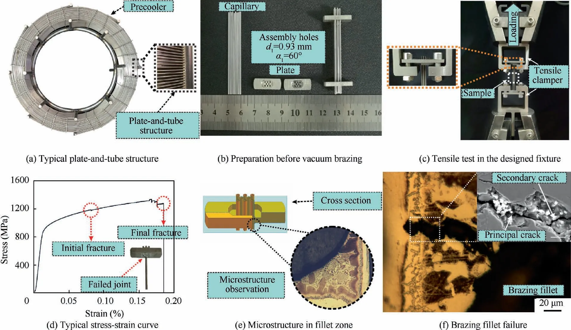
Fig. 1 Illustration of preparation and testing for brazed ultrathin-walled structure.
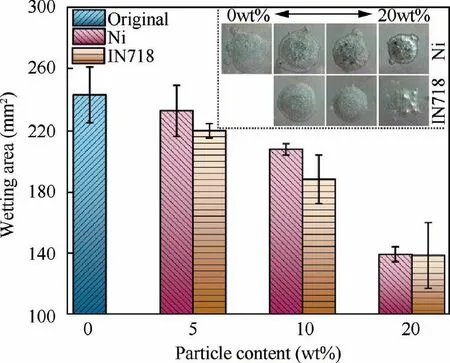
Fig. 2 Variation of the brazing droplet wetting area in different type and content of reinforced particles.
As shown in Fig.2,with the increase of the content of reinforced particles, the wetting area of the molten droplet decreases. Moreover, the wetting area of the composite filler alloy with 5wt% reinforced particle presents little difference with the initial filler alloy, showing the excellent wettability.And the spreading area of the different composite filler alloy with 10wt% reinforced particle presents 14.46% and 22.30%decrease than the initial filler alloy. However, by comparing the initial condition, the wetting area decreases ~43% with increasing the reinforced particle to 20 wt%.
Fig.3 shows the microstructure of brazing droplet with the excessive reinforced particle. Compared with the microstructure of brazing droplet with the initial filler alloy,the continuous eutectic microstructure was dispersed in the brazing droplet with composite filler alloy, and more Ni-based solid solution region could be observed. Similar to the spreading experiment results, the wetting angle of the 20wt% particle reinforced composite filler alloy increases significantly. The 1.6°wetting angle of the initial filler alloy presents a good wettability, however,the wetting angle increases to 8.1°and 10.5°with increasing the different reinforced particle to 20wt%.Moreover, the internal cracks and holes caused by excessive reinforced particles was presented in Fig. 3(c). It could be observed that there are some unmelted and semi-melted particles around the defects. With the increasing reinforced particles, the liquid phase provided by the initial solder decreases significantly. The diffusion behaviour between the reinforced particles and filler alloy result in the variation of the actual liquidus temperature. The solidification behavior starts on the dispersed particle sites, and the defects caused by insufficient liquid phase are easily formed at the interface of actual liquid interface during the cooling process. When brazing the array distributed ultrathin-walled plate-and-tube structure of the precooler, the insufficient liquid phase would easily result in the non-uniform spreading behaviour. The sectional microstructure of the uneven surface in the brazed ultrathinwalled structure was presented in Fig. 3(d). The non-uniform spreading behaviour is easy to lead to the local brazing filler alloy shortage, resulting in the decrease of structural strength and the leakage of coolant. According to the result of the spreading experiment, the effect of composite filler alloy with additive IN718 particles on reducing wettability is more prominent.
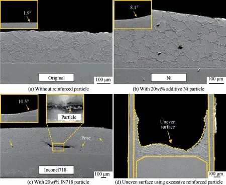
Fig. 3 Cross section of brazing droplet in spreading experiment.
The change of the solidus–liquidus temperature caused by different reinforced particles is the main reason for the spreading pattern variation. During the solidification process, the variation of the liquidus temperature is determined by the distribution equilibrium coefficient (k).The element Fe and Cr dissolved from the IN718 particles,which has a larger distribution equilibrium coefficient than the unity, increasing the liquidus temperature. A similar phenomenon has been reported by Ghasemi.Moreover, the element Al, Ti and Nb have a strong tendency to segregate in the Ni-based solute, resulting in the change of the local liquidus temperature.Furthermore,the formation of the G-phase could be promoted by element Nb has been affirmed in our previous work.The consumption of element Si induced by the diffusion of element Nb,Al and Ti would lead to an increase in the liquidus temperature. Consequently, the difference in wetting behaviour might be caused by the different elements in the reinforced particle.
In order to further investigate the effects of different additive reinforced particles on phase transformation behaviour during the melting and solidification process, the TG-DSC experiment was carried out, and the result was presented in Fig. 4. The endothermic and exothermic peaks present the phase transformation events in the DSC curve during the brazing process, and the values of the peaks reflect the intensity of phase transformation. It could be seen from Fig. 4a, the heating curve shows little difference in the starting point of the endothermic peak, which reflects the different composite filler alloy starts melting at 1076 ℃and the solidus temperature might not be influenced by the additive reinforced particles.Meanwhile,the endothermic peaks of the composite filler alloy are lower in value than that of the initial filler alloy.The difference in heat absorption illustrates the diffusion behaviour between the reinforced particles and filler alloy has been generated during the heating process.
The jagged exothermic peak presented in Fig.4(b)indicates a series of solidification events during the cooling process.From the DSC results presented in Fig. 4(b), it could be concluded that he liquidus temperature of the three different filler alloy is 1180 ℃, 1144 ℃and 1131 ℃, respectively. Moreover,the IN718 particle is more effective for improving the liquidus temperature than that of Ni particles. Compared with the result of the initial filler alloy,the DSC curve of the IN718 particle reinforced filler alloy presents a rapid return to the baseline reflects there might be some semi-melting particles in the melting liquid. The difference in shape and the magnitude of the exothermic peak indicates the diffusion phenomenon has mainly occurred during the heating process,although no additional holding time at the brazing temperature.
Fig.5 shows the calculated liquidus surface in the Cr-Ni-Si ternary system.The actual composition point of the Ni71CrSi is given in the ternary phase diagram. It could be concluded that the liquidus temperature of the filler alloy is lower than 1200 ℃and there exists a ternary eutectic point Enear the actual composition point.The corresponding ternary eutectic reaction is L ↔(Ni)+NiSi+CrNiSi.
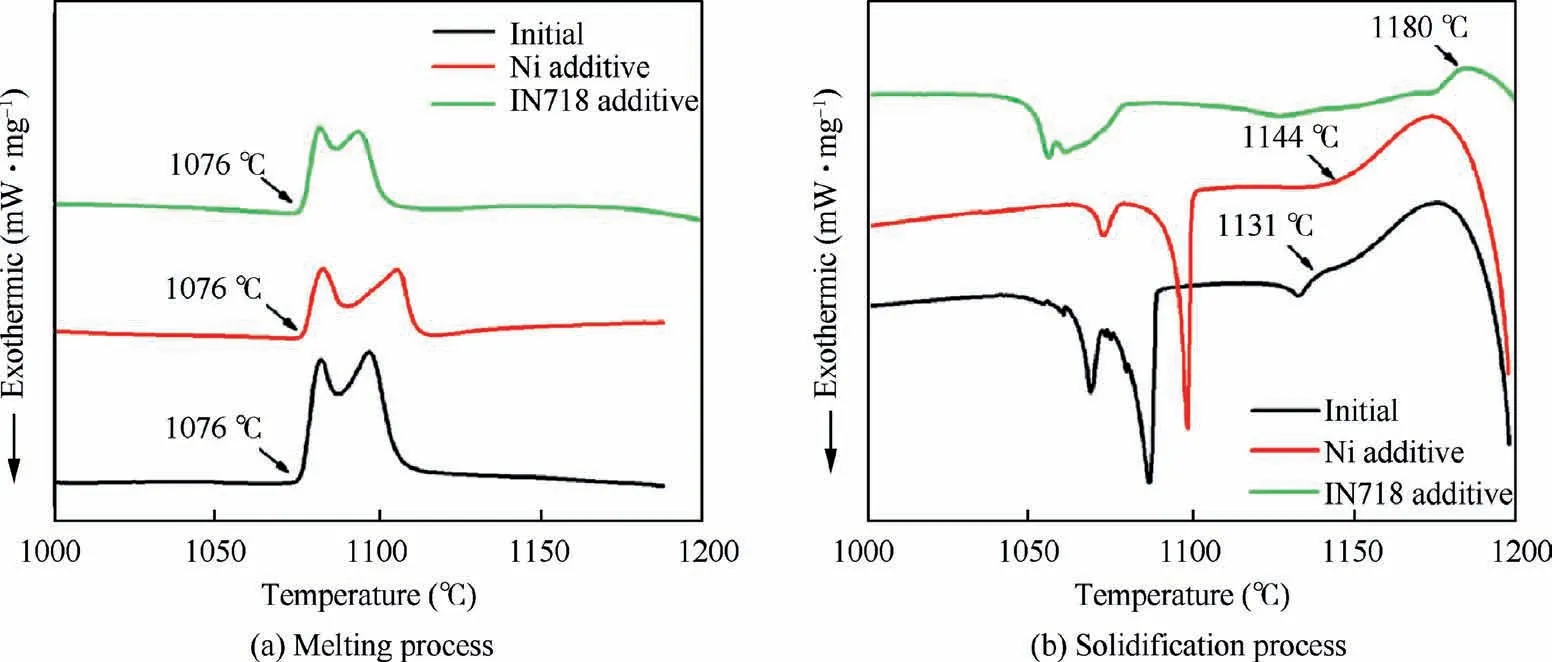
Fig. 4 DSC curves of composite filler alloy using a different type of additive particle.
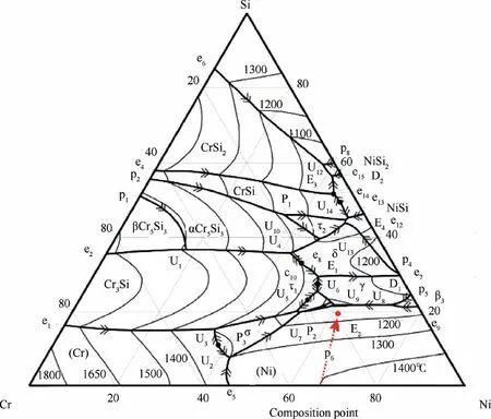
Fig. 5 Calculated liquidus surface in Cr-Ni-Si ternary system.35
Fig.4(b)shows three distinct exothermic peaks in the DSC traces and the liquidus temperature of 1135 ℃ has been reported in some investigations.Meanwhile, the chemical consumption of Ni71CrSi might be located in the actual real liquid region at 1135 ℃.Therefore,the first exothermic peak observed about 1135 ℃is related to the appearance of solid phases. As shown in Fig. 5, the actual composition point of the Ni71CrSi is close to the eutectic point E,with the solidification of molten solder and the change of chemical composition, the possible reaction path could be expressed as: e→D→U→E. A series of reactions could be expressed as L→(Ni)+β-NiSi (e), L+β-NiSi →β-NiSi (D), L+β-NiSi→(Ni)+NiSi(U), L→(Ni)+CrNiSi+-NiSi(E). According to some investigations on phase equilibria of the Cr-Ni-Si ternary system, a ternary eutectic reaction L ↔ (Ni)+NiSi+CrNiSi(20at% Cr and 20at%Si)could be detected at 1077 ℃.In addition,the reaction was also affirmed in Cr-Ni-Si ternary system by Schuster,but the temperature of 1084±2 ℃was a little deviation with the investigation mentioned above.Consequently,it could be concluded that the second exothermic peak of 1086 ℃is caused by the ternary eutectic reaction. It could be observed from Fig.4(b),the onset temperature of the second exothermic peak in DSC traces of composite filler alloy using Ni particles and IN718 particles are 1100 ℃and 1079 ℃, respectively. During the heating process, the acute diffusion phenomenon between the additive reinforced particles and filler alloy results in the increase of the element Ni content in the melting liquid.According to the calculated liquidus surface of Ni-Cr-Si ternary equilibrium system presented in Fig. 5, the increasing Ni content makes the chemical composition position of the composite filler alloy move towards the Ni edge of the isothermal section, which results in the actual composition point approach the border of the liquid region and solidification occurs in advance. Moreover, the diffusion phenomenon between additive IN718 reinforced particles and melting filler alloy increases the element Ti,Nb and Mo in the liquid,which have a lower distribution equilibrium coefficient (k) than the unity,reducing the phase transition temperature.As presented in the DSC curves, the third exothermic peak around 1068 ℃during the cooling process, which corresponds to the first endothermic peak around 1076 ℃, might be related to rapid solidification of the residual liquid. The high cooling rate and nonuniform elements distribution promote the formation of the non-equilibrium microstructures at the third exothermic stage.
Therefore, the change of composition caused by reinforced particles is the main reason for the change of exothermic peak position. The second exothermic peak value of IN718 particle reinforced filler alloy decreases obviously,which indicates that the ratio of residual liquid phase in the ternary eutectic reaction decreases. Meanwhile, the change of exothermic peak value also indicates that the content of IN718 particles is higher than that of Ni particles in the strengthening behaviour.
3.2. Microstructure of the brazing region
The brazed ultrathin-walled plate and tube structure was achieved at 1170 ℃using the different type of composite filler alloy. The formation of a smooth fillet reveals the excellent wettability between the filler alloy and the base material.Fig. 6(a) presents an overview of the brazing fillet obtained using the initial filler alloy. As shown in Fig. 6(a), the brazing fillet primarily consists of four zones: isothermal solidification zone (ISZ), athermal solidification zone (ASZ), diffusion affected zone (DAZ) and base metal (BM). The BM is composed of plate and capillary.The ISZ and DAZ mainly contain a layer of primary γ-Ni solid solution and precipitates. Moreover, the ASZ is composed of a large number of the eutectic structures and eutectic γ-Ni solid solution, which formed during the athermal solidification process.The detailed monopoly of the microstructure is magnified in Fig.6(d)-(f)and the summary of the chemical composition are listed in the Table 2.
To investigate the effects of different reinforced particles on the microstructure evolution in the brazing fillet, the SEMEDS was used to identify the microstructure composition and distribution.It can be seen from Fig.6(a)-(c),three significant differences could be observed with the addition of the reinforced particles. First, one can see that the area of the eutectic phase is replaced by the area of γ-Ni solid solution.Second,the eutectic phase distribution becomes more uniform and dispersed. Third, compared to the Ni reinforced particles,the effect of IN718 reinforced particles on dispersing the eutectic structure is more prominent.Based on the EDS results and our previous work,the microstructures formed in the joint was confirmed, and the suggested phases were summarized in Table 2. The detailed monopoly of the needle-like precipitates was shown in Fig. 6(d). According to our previous researches,the needle-like precipitates distributed at the solid–liquid interface might form in the isothermal solidification process. Moreover, the chemical composition of the precipitates was similar to the G-phase, presenting a characteristic of high Nb content. Since the precipitation process of the precipitates is accompanied by the nucleation of the solid solution base material, the precipitates tend to form at the grain boundaries. The details of the microstructures of the eutectic island brazed using different reinforced particles was shown in Fig. 6(e)-(f). Several typical intermetallic phases were confirmed: NiSi, CrNiSi, (Cr, Nb, Ti)(Ni, Fe)Si(usually called the G-phase) and γ-Ni solid solution. The eutectic islands presented in Fig.6e and f generate in the cooling process. The morphology and microstructure of eutectic island are determined by the distribution of dendrites and distribution equilibrium coefficient. Unlike the microstructures formed in the brazing fillet using the initial filler alloy,the Cr-NiSiphase was not detected in the eutectic island.Due to the low solubility of element Al, Ti and Nb in Ni, these elements are rejected into the residual liquid phase during the growth of dendritic solid solution, resulting in a large concentration gradient in the real solid–liquid interface. According to the previous investigation,the formation of the CrNiSiis mainly controlled by the further diffusion of element Cr in Ni-Siand the eutectic reaction L ↔(Ni)+NiSi+CrNiSi.Meanwhile, the element Nb and Ti are detrimental to the stability of CrNiSiphase. Consequently, the formation of the CrNiSiphase is affected by the residual liquid phase volume and the content of element Ti and Nb in the liquid phase during the ternary eutectic reaction.It could be concluded that the increase in the content of element Nb and Ti and the decrease in the volume of the residual liquid phase participating in the eutectic reaction would result in the CrNiSiphase to be difficult to detect in the eutectic island.
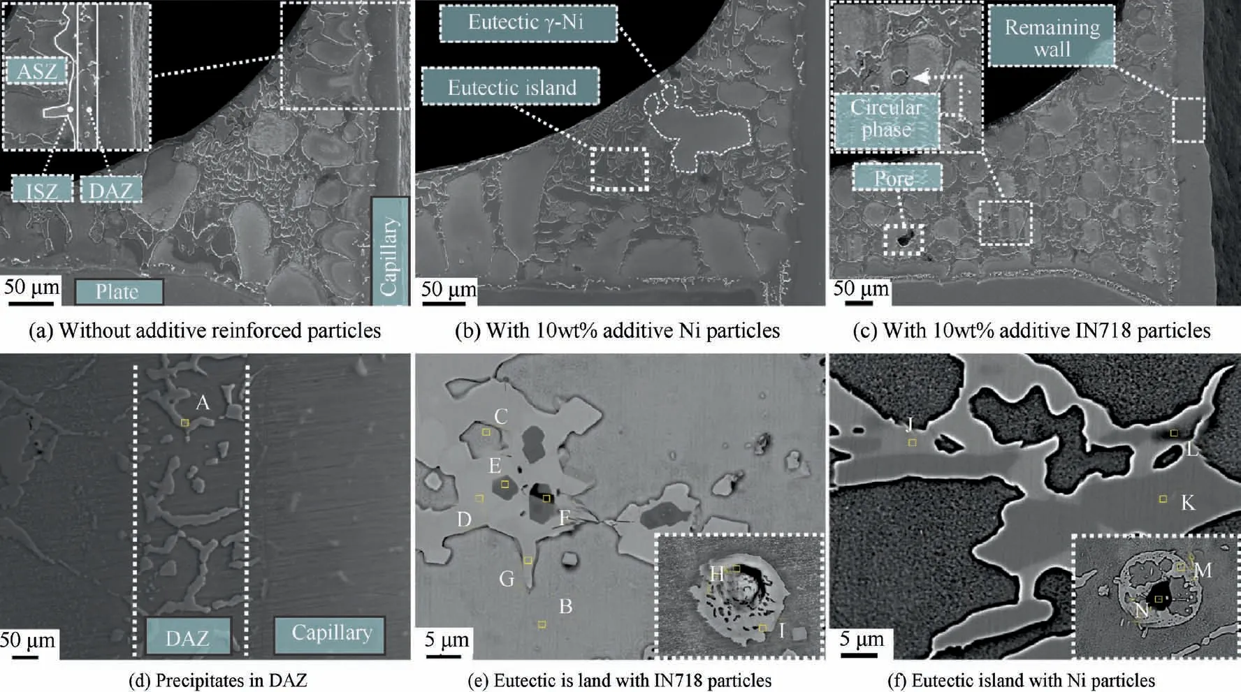
Fig. 6 Microstructures of brazed fillet with initial filler alloy.

Table 2 Chemical composition (at%) and possible phases of various spots marked in Fig. 6.
The higher magnification of the nucleation sites (see Fig. 6(e)and(f))shows that the nucleation particles exist in the form of circular intermetallic compounds.The difference in the morphology of the intermetallic compounds at the nucleation site is caused by the different phase transformation process. The circular phase formed at IN718 nucleation particles is similar to the needle-like precipitates in DAZ.The element Si diffuses into the particles during the holding process and precipitates with the decrease of the solubility during the cooling process,which is a eutectic mixture of γ-Ni and G-phases with a low Nb content. However, different from the IN718 reinforced particle,the epitaxial growth of intermetallics from the surface of Ni particles and some evident solid solution could be observed. That might be related to the dissolution behaviour of the Ni particle at the high brazing temperature. Due to the low solubility of element Nb in Ni, the dissolution of Ni particles results in the rejection phenomenon of element Nb.Consequently,the phases formed at the Ni nucleation particles mainly consists of NiSiand CrNiSi.
Fig. 7 presents several typical stages of the solidification process using particle reinforced composite filler alloy.In stageⅠ(heating and melting),when heated up to the liquidus temperature of the initial filler alloy, the molten filler alloy formed and the reinforced particles were surrounded by the molten liquid phase.In stage Ⅱ(holding and interacting),at high brazing temperature, the dissolution and diffusion behaviour of the base material and reinforced particles result in the change of the molten brazing alloy composition, and then the variation of the solidus–liquidus temperature. The molten matrix provides sufficient fluidity for the reinforced particles, and aggregation behaviour might occur under the influence of the Gibbs-Thomson effect. This phenomenon would result in the local solute deficiency during the cooling process,which might lead to the formation of the micro-void at the intersection of the eutectic structure. In stage III (holding and isothermal solidifying), a thin layer of equilibrium γ-Ni solid solution forms on the interface of the reinforced particle and base metal.It is the result of the change of the liquidus-solidus temperature induced by the dissolution behaviour.The dissolution and diffusion of the particles form a spherical inhomogeneous zone of the elements.According to the Ni-Si binary phase diagram,when the composition of the molten liquid phase reaches the line of L+(Ni) region at holding temperature,the Ni solid solution occurs and expands outwards along with the interface of the reinforced particle in a cellular pattern.Meanwhile,the diffusion of element Si into the capillary result in the initial formation of the precipitates.In stage Ⅳ(cooling and athermal solidifying), the undercooling provided by cooling is much larger than that provided by the component gradient,which promotes the nucleation.A great number of dendric solid solution expands rapidly on the interface of the base metal and additive particles. The γ-Ni solid solution tends to merge under the influence of the Gibbs-Thomson effect. The limited solubility of element Si, Ti and Al in Ni results in the rejection phenomenon into the residual molten liquid phase during the solidification process. The rapid shrinkage of the molten alloy would provide the possibility of the formation of the micropores at the interface of the liquid phase. When the element Si content is higher than the solubility of Si in γ-Ni, the eutectic structures are formed in the residual brazing liquid and the nucleation sites. As the temperature decrease,the non-equilibrium eutectic structures generate and the intermetallic phase precipitates in DAZ.
3.3. Mechanical properties of brazed ultrathin-walled structure using a different type of composite filler alloy
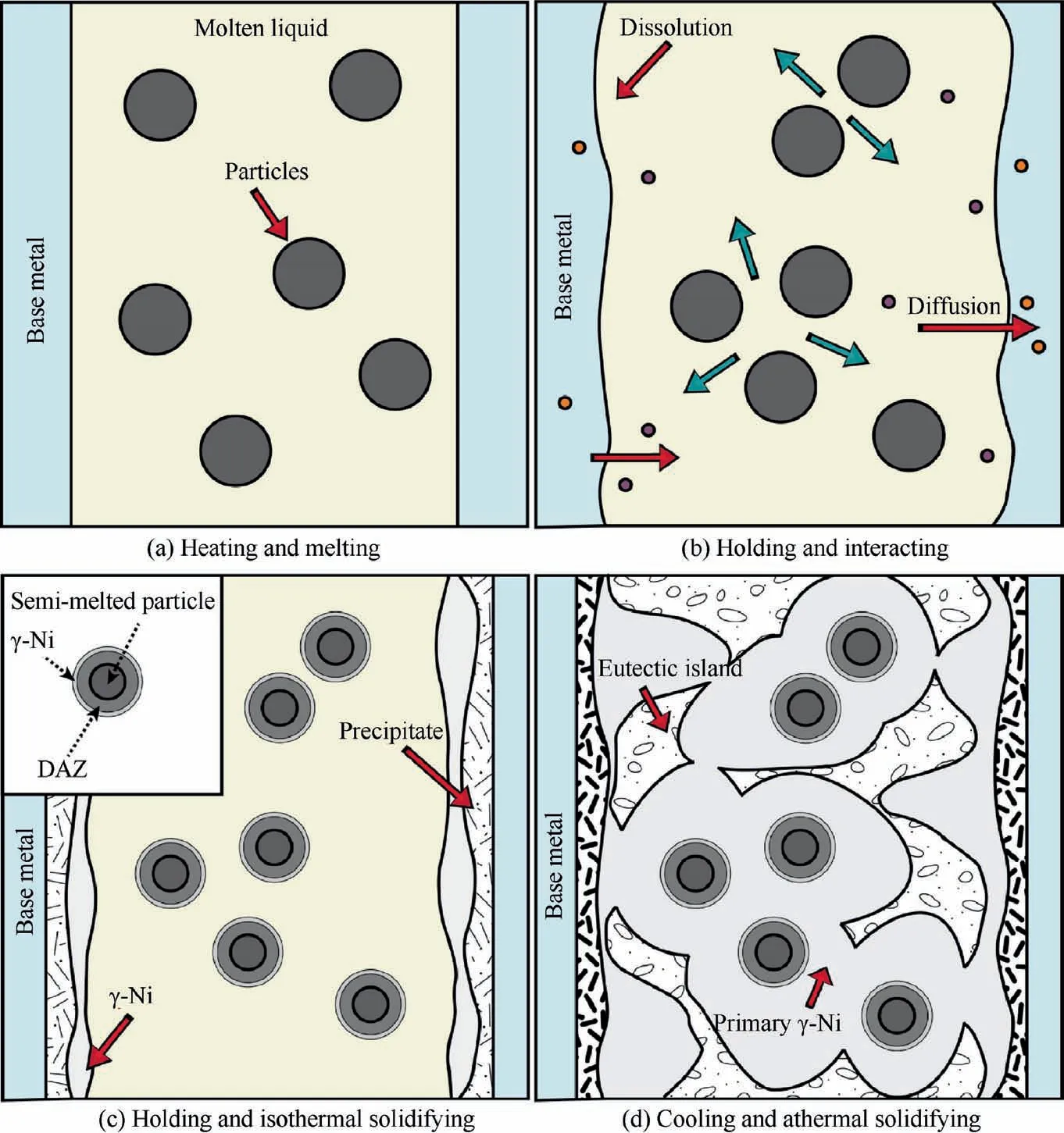
Fig. 7 Illustration of solidification process using particle reinforced composite filler alloy.
The purpose of this section is to outline the performance of the brazed ultrathin-walled structure using a different type of composite filler alloy. The brazing experiments were carried out at 1170 ℃, and then the tensile tests for the brazed ultrathinwalled structure were conducted. In this section, the tensile strength,dissolution width W,engineering strain ε and plastic strain εwere selected to evaluate the properties of the brazed joint. The dissolution width Wwas obtained by initial capillary wall thickness minus remaining capillary wall thickness after brazing.The remaining capillary wall thickness was illustrated in Fig. 6(c) and measured by optical microscope.
The summary of mechanical properties evolution influenced by the different types and contents of the reinforced particle is presented in Fig. 8. According to the results of the mechanical properties, one can see that the addition of the reinforced particle has a positive effect on the mechanical performance of the brazed ultrathin-walled structure. Compared to the results of the brazed samples using initial filler alloy,there is a marked improvement in the tensile strength of the brazed samples using composite filler alloy. Furthermore, the influences of the reinforced particle on the tensile strength of the brazed ultrathin-walled structure is not the same in different types and contents. The increase has been found more obvious for the samples brazed using 10wt% additive particle reinforced composite filler alloy, which presents 6.74% and 9.36% (Ni and IN718 particles) higher than the samples brazed with initial filler alloy.However,it should be noted that the further increasing additive reinforced particles to 20wt%would lead to the reduction of the tensile strength,which exhibits a 2.8%and 1.28%drop from the peak value.According to the results obtained in Fig.8(a),the IN718 reinforced particles are more beneficial for improving the tensile strength of the ultrathin-walled brazed structure. Fig. 8(a) also shows the effect of reinforced particles on the dissolution behavior of the ultrathin-walled capillaries at high brazing temperature.It could be seen that the dissolution width Wof the capillary using the initial filler alloy is 29 μm,which is more than half of the capillary wall thickness.Futhermore,the dissolution width Wdecreases obviously by using the composite filler alloy.When increasing the reinforcement particles to 20wt%,the dissolution width Wis reduced to ~11 μm,which is 165%lower than the original filler alloy. Based on the result of the influences of two different type particles on the ultrathin-walled capillary high temperature dissolution behaviour, the IN718 particles presents more effective effects on reducing the high temperature solidification behavior of the capillary. As an example, the dissolution widths Wof two different particle type composite filler alloy (Ni particle and IN718 particle)are 22.4 μm and 15 μm respectively. The dissolution width Wof capillary using IN718 particle reinforced composite filler alloy is 33% lower than that using Ni particle reinforced composite filler alloy.
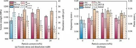
Fig. 8 Effects of varying type of reinforced particle on mechanical properties of brazed ultrathin-walled structure.
Fig.8(b)presents the variation of the tensile strain with the different types and contents of the reinforced particle. The results have demonstrated that the additive reinforced particles provide a positive effect on improving the elongation of the brazed ultrathin-walled structure. Similar to the results of the tensile strength, the ultrathin-walled structure brazed with 10wt% additive Ni particle reveals the highest engineering strain ε, which is 35.97% higher than the joint brazed using the initial filler alloy.Besides,the plastic strain εof the brazed ultrathin-walled structure increases by 31.87%. Moreover,compared to the results obtained using initial filler alloy, the engineering strain ε increases by 54.06% and 47.27% when brazed using 5wt%and 10wt%IN718 particle reinforced filler alloy. Furthermore, the plastic strain εalso presents 79.16%and 67.70% higher than the samples brazed without additive particles. However, a noticeable decrease in the value of the engineering strain ε and plastic strain εoccurs in further increasing the content of the reinforced particles.
According to the experimental results shown in Fig. 8, it could be concluded that the additive IN718 reinforced particles offers better mechanical performance than Ni reinforced particles. Moreover, it could be confirmed that the mechanical properties of the ultrathin-walled structure could be improved by using Ni71CrSi+5wt%-10wt% reinforced particle composite filler alloy,however,the mechanical performance might be weakened by adding excessive reinforced particles.Based on the analysis of the strain change among varied particle contents, the engineering strain ε of the samples brazed using 10wt% different reinforced particle composite filler alloy reveals a 35.97% and 47.27% increase respectively. However,the plastic strain εpresents a 31.87% and 67.70% increase.According to the variation of the engineering strain ε and plastic strain εincrement, it could be deduced that the contribution of the reinforced particle to the elongation of the brazed ultrathin-walled structure primarily comes from the evolution of the plastic deformation behaviour.
The changes in mechanical properties caused by different types and contents of the reinforced particles could be explained as follows. When heated up to the melting point of the filler alloy, the clearance between the capillaries and plate is filled with the molten filler alloy,then the brazing fillet forms during the solidification process. During the cooling process,the generation of the non-equilibrium intermetallic compounds would provide a preferred low resistance path for crack propagation. In this work, the hard and brittle intermetallic compounds formed in a shorter holding time is inevitable. The related investigation has reported that the formation of the hard and brittle intermetallic compounds provide a large number of the crack nucleation sites, which results in the remarkable decrease of the mechanical performance.Moreover,the brazing fillet also presents a high-stress region and eventually leads to structural failure.Consequently, stress concentration in the brazing fillet might be caused by two aspects:structural discontinuities and formation of blocky hardbrittle phases. Besides the higher brazing temperature could increase the solubility of base metal and weaken the strength of base metal, especially for the ultrathin-walled structure.The over-dissolution of the base metal phenomenon caused by high brazing temperature has also been reported in previous studies.Furthermore, the diffusion behaviour of element Si is improved significantly at higher brazing temperature,which has low solubility in Ni.And then the long diffusion distance of Si in capillaries promotes the formation of the Ni-Si-Nb intermetallic compounds at the deeper location in the ultrathin-walled base metal.The tendency of the hard and brittle intermetallic compounds precipitate in grain boundary would result in the stress concentration and grain boundary weakening of the base metal, which has been reported in our previous work.Consequently,the over-dissolution behaviour and the formation of the Ni-Si-Nb precipitates in the ultrathinwalled base material induced by higher brazing temperature might provide negative effects on brazing the ultrathinwalled structure.
According to the results obtained before, the mechanical properties are promoted significantly by using the particle reinforced composite filler alloy.The large blocky eutectic phase in the brazing fillet formed during the athermal solidification would result in the stress concentration, and provide a low resistance path for crack nucleation and propagation. During the solidification process,the unmelted and semi-melted particles would provide a considerable quantity of contacting surface, which could act as the nucleation sites in the free molten liquid and provide the bridge path.The γ-Ni solid solution generated at the uniformly distributed nucleation sites plays a role in separating the large blocky eutectic structure.Moreover, the random distributed solid solution with better plasticity provides a barrier for crack propagation. The dispersed eutectic structure effectively reduces the possibility of stress concentration and crack initiation in the fillet region.Fig. 8b presents the change of strain under different types and contents of the reinforced particle, and it could be concluded that the increase of structural elongation is mainly caused by the increase of plastic deformation capacity.During the tensile process,the enlarged solid solution region alleviates the deformation discontinuity of the brazing region and consume more plastic work, which improves the mechanical performance of the brazed ultrathin-walled structure. However,with the increase of the reinforced particle content, the local solute deficiency caused by the acute diffusion behaviour would increase the porosity in the brazing region,which weakens the mechanical performance.
On the other hand, the mechanical performance of the ultrathin-walled structure depends on the properties of brazing region and the strength of ultrathin-walled capillaries. Different from the traditional brazing structure,the change of capillary strength has obvious effect on the ultrathin-walled structure performance.According to the variation of structure strength and dissolution width W,it could be concluded that the decrease of the dissolution width Wof the capillary caused by the reinforced particles is beneficial to the increase of the structural strength.This is because the dissolution behaviour of ultrathin-walled capillary is affected by composition gradient, brazing temperature, holding time and the melting filler alloy volume. The liquid phase at brazing temperature is mainly provided by the initial filler alloy, and the volume of free liquid phase decreases with the increase of reinforced particle content at brazing temperature. Consequently, compared to the dissolution width Wof the capillary using initial filler alloy, the dissolution width Wdecreases obviously by using the composite filler alloy. The diffusion behaviour between the IN718 particles and the molten filler alloy increases the actual liquidus temperature of the filler alloy,which makes the solidification process faster than that of the Ni particle reinforced composite filler alloy. Therefore, compared to the Ni particle reinforced composite filler alloy, the smaller dissolution width Wis obtained by using the IN718 reinforced particles. However, However, when the particles are increased to 20wt%, the liquid phase of the two different composite filler alloy is insufficient, the dissolution width Wis basically the same.
Different from the traditional brazed structure, the diffusion behaviour from the brazing region into the capillary play an important role on the mechanical performance of the ultrathin-walled structure. According to the previous study,the precipitates formed in the base material might result in a decrease of the mechanical properties, especially for the ultrathin-walled structure.The precipitates formed near the solid–liquid interface is a eutectic mixture with comparison close to G-phase.The presence of the element Nb in base metal, which is a strong G-phase former, would promote the formation of the precipitates in the diffusion zone. Based on the binary phase diagram, the limited solubility of Si in Ni is 8wt% and decreases with decreasing temperature. During the brazing cycle, a large amount of element Si diffuses into the DAZ and precipitates with the decrease of the solubility.Solute rejection behaviour generally occurs during the isothermal solidification process. More nucleation sites are involved in the solidification process,which reduces the solute repulsion on the base metal surface and the diffusion of Si into the capillary. Compared to the initial filler alloy, solidification and eutectic reactions occur at more nucleation sites, which increases the consumption of the element Si and reduces the diffusion flux of Si to the basis metal.Meanwhile,the diffusion behaviour between the particles and the molten brazing filler alloy results in the reduction of the residual liquid phase,which further weakens the precipitation behaviour in DAZ. Consequently, it could be concluded that the addition of reinforcement particles affects the formation of precipitates in the diffusion zone,which is beneficial for mechanical performance.
According to the change of mechanical properties of the brazed ultrathin-walled structure caused by different reinforced particles, it could be confirmed that the effect of IN718 particles on the performance improvement is more evident than the pure Ni particles. During the high-temperature brazing cycle, the solubility of element Ni in γ-Ni solid solution is much higher than that of element Cr,Fe,Nb,Mo.Consequently, more nucleation sites could be provided by the additive IN718 reinforced particles in the molten brazing alloy.Moreover,the more element Si would be consumed by the diffusion phenomenon between the molten brazing filler alloy and the IN718 particles, which improves the isothermal solidification behaviour in brazing zone and hinders the generation of the precipitates in the capillary. Meanwhile, the lack of metallurgical reaction between Ni particles and molten solder might provide negative effects on guaranteeing the interfacial force between the reinforced particle and the matrix.The mechanism of solid solution strengthening depends on the degree of mismatch between solute and solvent atoms. The element Nb,Mo and Ti diffused from the IN718 particles have a significant contribution to the solid solution strengthening of the brazing region.In addition,the more element Nb and Ti in the brazing region are beneficial to the formation of the γ’ and γ’’strengthening phases,which improves the ageing strengthening ability of the brazing region. Consequently, it could be concluded that the composite filler alloy using IN718 particles as reinforcement particles has more advantages than the pure Ni particles in brazing ultrathin-walled structure.
3.4. Effects of the reinforced particles of the micro-hardness distribution of the brazed joint
Considering the limited testing area of the brazed ultrathinwalled structure and instability behaviour of the ultrathinwalled base material caused by the testing head, resulting in the fluctuation and distortion of the detection data. Consequently,the brazed sandwich structure was used to investigate the influences of the different types of the reinforced particle on the micro-hardness distribution of the brazed joint, which was used to investigate the failure behaviour of the brazed ultrathin-walled structure in our previous study.For each test point, the indenter pressure was selected as 200 g, and the detection distance was selected as 50 μm.
In order to study the effect of reinforced particles on the micro-hardness distribution of the brazed joint, the microhardness of several typical microstructures were measured,and the results were listed in Table 3. Each average microhardness of microstructures was conducted at 10 points. It should be noted that the Ni-Si binary eutectic phase and Cr-Ni-Si ternary eutectic phase could hardly be distinguished under the optical microscope. The result indicates that the average micro-hardness of the primary solid solution in ISZ is 304 HV,which is significantly lower than that of the eutectic structure in the brazing region.However, the average Vicker’s hardness of the solid solution generated during the athermalsolidification process is 439 HV, which is higher than the primary γ-Ni solid solution formed during the isothermal solidification process. The highest average micro-hardness of 708 HV was detected in the eutectic structure, which presented the hard and brittle characteristics. According to the different proportion of the solid solution and the eutectic phase in the indentation area, the average micro-hardness varies from 300 to 700 HV.
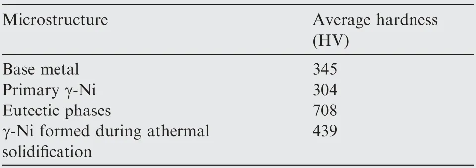
Table 3 The average microhardness of different microstructures tested in the sectioned joint.
The contour plots for the micro-hardness distribution of brazing region in different composite filler are presented in Fig. 9. Each contour plot is generated from the data of 120 individual detection points. According to the average microhardness values obtained in Table 3, in this work, the microstructure with the micro-hardness more than 700 HV is considered to be the eutectic phase, which is shown as dark red in the contour plots. As shown in the Table 3, the γ-Ni solid solution formed during the athermal solidification process presents a higher micro-hardness value than the primary γ-Ni solid solution. As the γ-Ni solid solution formed during the athermal solidification process is supersaturated nonequilibrium solid solution structure, the increasing content of solid solution strengthening elements (i.e. Cr, Fe) would provide a positive effect on matrix strengthening.Also,it has been demonstrated that a great number of fine NiSi phase would precipitate from the supersaturated solid solution during the cooling process in our previous research.Therefore, the precipitation behaviour would increase the micro-hardness of the region. As shown in Fig. 9(b), different microstructures could be distinguished clearly, and the BM and γ-Ni solid solution exhibit softer characteristics.The continuous eutectic structure could be indicated in the centreline of the brazed joint. In a small range, the significant properties difference between the base metal and brazing region is detrimental to the structural strength. Particularly, the severe hardness gradient between the γ-Ni solid solution and the eutectic structure is prone to cause the uncoordinate deformation under complex loading conditions, which would result in the initiation and propagation of the cracks. It could be seen from Fig. 9(c) and (d),the continuous and concentrated dark red high hardness zone was separated into several individual parts,which indicated the reinforced particles could disperse the continuous eutectic phase effectively. And compared to the result using Niparticle reinforced composite filler alloy, the dispersion behaviour of IN718 particles on the continuous eutectic phase is more apparent than Ni particles, and the high hardness area decreases. According to the micro-hardness distribution data of the testing region,the sample brazed using Ni-particle reinforced composite filler alloy produced a brazed joint with an average hardness of 462 HV, which is similar to the result of the sample using initial filler alloy (≈465 HV). However, the average hardness was decreased to 431 HV by using IN718 reinforced composite filler alloy.During the solidification process, the higher free energy is provided by the surface of the unmelted and semi-melted reinforced particle, and then the eutectic structure is divided into several individual parts by the nucleation and growth of the dendritic γ-Ni solid solution on the particle surface. The dissolution rate of IN718 particles is relatively lower than that of Ni particles under the high brazing temperature condition,which provides a higher probability of nucleation for the dendrites. Eventually, the lower average hardness of the brazed sample is obtained.
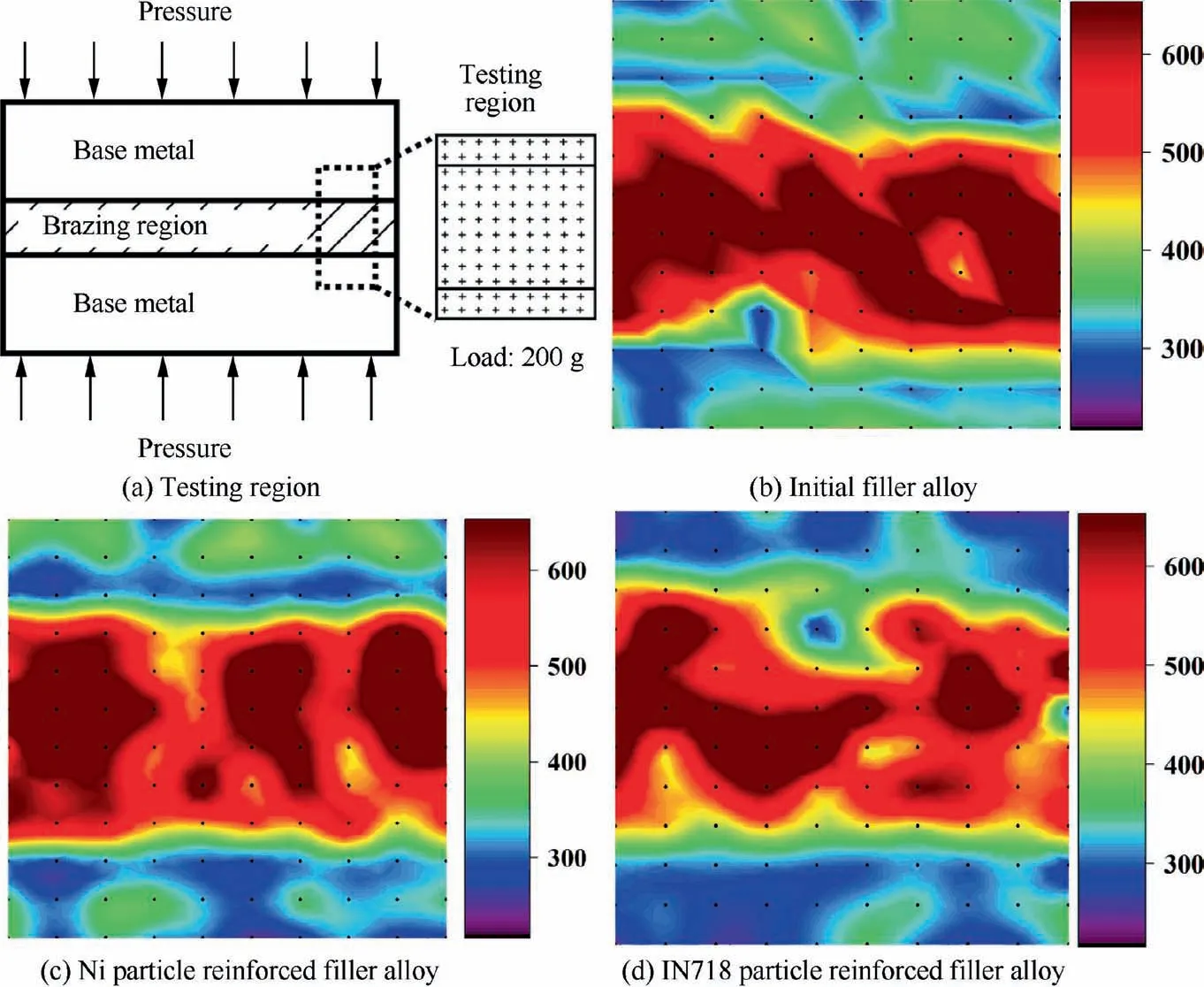
Fig. 9 Micro-hardness distribution results of brazed joint using different composite filler alloy.
As the brazed joint is symmetrical, half of the brazing region was tested to analyze the micro-hardness profile, the results were presented in Fig. 10(a). The average hardness of each position was performed at 10 test points.It could be seen from Fig. 10(a), the average micro-hardness of the ASZ is obviously higher than that of BM and ISZ. The peak value of the micro-hardness was detected at centreline, and the lowest value was detected in the ISZ region. The interdiffusion phenomenon of the alloy elements is the decisive factor of the hardness in the ISZ region, which has been demonstrated in Pouranvari’s study.Therefore, the micro-hardness of the ISZ zone is lower than that of BM could be caused by the lower content of solid solution strengthening elements.
In order to further investigate the effects of different reinforced particles on the micro-hardness distribution, the micro-hardness box plot and normal distribution of 30 individual test points on the centreline are presented in Fig.10(b).The upper quartile and lower quartile are used to reflect the dispersion of hardness data distribution. It indicates the average hardness varies in different composite filler alloy and the average hardness value are 663 HV, 626 HV and 566 HV, respectively. It could be seen from the normal distribution of the individual hardness data, and the hardness dispersion could be increased by the reinforced particles significantly. Furthermore, the results of the box plot indicate the brazed sample using IN718 particle reinforced filler alloy presents a greater range and interquartile spacing of the micro-hardness. As a result, the hardness distribution concentration could be reduced by the reinforced particle,and the effect of IN718 particles is more evident than the Ni particles.The results could be explained as follows. The solidification behaviour of the molten solder starts from the surface of BM, which results in a eutectic structure formed in the centreline during the athermal solidification process. The random distribution of the reinforced particles and the irregular growth of the dendritic γ-Ni solid solution decreases the average hardness of the centreline. The results of micro-hardness distribution in the brazed region seem to confirm well the change of the mechanical properties of the ultrathin-walled brazed structure. The relatively lower overall brazed sample hardness and the high hardness region was dispersed by the random dendritic solid solution,which would reduce the risk of failure caused by the stress concentration at the brazing fillet. According to some investigations, the uniform distributed microstructure could reduce the coefficients of thermal expansion mismatch and the residual stress of the brazed joint,which could improve the mechanical properties of the brazed joint.The mixed soft solid solution could consume more deformation energy, endure more significant incompatible deformation behaviour and prevent crack propagation, which improves the plastic deformation ability of the brazed ultrathin-walled structure.
4. Conclusion
In this study, the experiments for vacuum brazing ultrathinwalled structure using different particle reinforced composite filler alloy were conducted. The reliable brazing joint was obtained.And then the microstructure evolution and mechanical performance of the brazing joint were investigated in detailed. The primary conclusions could be drawn as follows.
(1) The spreading behaviour could be influenced by the reinforced particles significantly. The 10wt% particle reinforced composite filler alloy could ensure the spreading of molten liquid phase at brazing temperature.And compared to the initial filler alloy, the spreading area decreases 14.46% and 22.30%. Excessive reinforced particles would increase the risk of defects caused by insufficient liquid phase.Compared to the Ni reinforced particles, the effect of the IN718 reinforced particles on the solute loss phenomenon is more obvious at brazing temperature.
(2) The typical microstructures of the brazed fillet zone are NiSi, CrNiSi, G-phase and γ-Ni solid solution.
The elements of Nb and Ti are the main reasons for the formation of the G-phase.The formation of the γ-Ni at the nucleation sites reduces the area of the blocky eutectic island and makes it more uniform distribution. Compared to the Ni particles, the IN718 particles reinforced composite filler alloy could provide more nucleation sites and more suitable in improving the microstructure distribution in the fillet region.
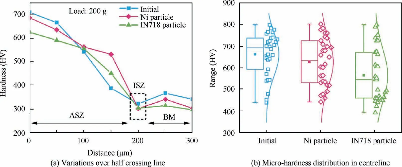
Fig. 10 Micro-hardness profile of brazed sample.
(3) The addition of an appropriate amount of the reinforced particles has great benefits for improving the mechanical properties of the brazed ultrathin-walled structure.Compared with the Ni particles, the performance of IN718 practice on improving mechanical properties is more obvious.The excellent performance of the brazed ultrathin-walled structure could be obtained by using the Ni71CrSi+10wt%IN718 particles reinforced filler alloy. The maximum tensile stress and engineering strain reach 1171 MPa and 14.86%,which presents 9.36%and 47.27%higher than the mechanical properties (1068 MPa and 10.09%) brazed using initial filler alloy.In addition,the increase of the elongation of the brazed joint is mainly contributed by the increasing plastic properties of the joint.
(4) The dissolution behavior of ultrathin wall base metal can be reduced by using the composite filler alloy. Compared with the initial filler alloy,the dissolution width Wof the capillary decreases by 24.07% and 49.15% respectively by using the 10wt% Ni and IN718 particle reinforced composite filler alloy, which results in the increase of the ultrathin-walled structural properties. Although the dissolution behaviour of ultrathin-walled capillary could be reduced by the excessive particles, the defects caused by insufficient liquid phase are unacceptable.
(5)The decrease in the overall brazed sample hardness and dispersion of centreline hardness is attributed to the reinforced particles.By using the IN718 particle reinforced composite filler alloy, the average hardness of the brazing region is dec reased to 431 HV from 465 HV and the average hardness of centreline is decreased to 566 HV from 663 HV. The IN718 reinforced particle provide more advantages than Ni reinforced particle in improving the mechanical properties and homogenizing eutectic structure.
The authors declare that they have no known competing financial interests or personal relationships that could have appeared to influence the work reported in this paper.
The authors would like to acknowledge the financial support by the project (No. JCKY2017601B013, JCKY2018601C207)from the Defense Industrial Technology Development Program, and the Jiangxi Research Institute of Beihang University.
