Modeling and flapping vibration suppression of a novel tailless flapping wing micro air vehicle
Siqi WANG, Bifeng SONG, Ang CHEN, Qing FU,*, Jin CUI
a School of Aeronautics, Northwestern Polytechnical University, Xi’an 710072, China
b Yangtze River Delta Research Institute of Northwestern Polytechnical University, Taicang 215400, China
c Research & Development Institute of Northwestern Polytechnical University in Shenzhen, Shenzhen 518057, China
d School of Aeronautic Science and Engineering, Beihang University, Beijing 100083, China
KEYWORDS Flapping vibration;Flapping wing;Linear quadratic theory;Robust control;State observer
Abstract This paper establishes and analyzes a high-fidelity nonlinear time-periodic dynamic model and the corresponding state observer for flapping vibration suppression of a novel tailless Flapping Wing Micro Air Vehicle(FWMAV),named NPU-Tinybird.Firstly,a complete modeling of NPU-Tinybird is determined, including the aerodynamic model based on the quasi-steady method, the kinematic and dynamic model about the mechanism of flapping and attitude control,combined with the single rigid body dynamic model. Based on this, a linearized longitudinal pitch dynamic cycle-averaged model is obtained and analyzed through the methods of neural network fitting and system identification, preparing for the design of flapping vibration suppression observer.Flapping vibration is an inherent property of the tailless FWMAV,which arises from the influence of time-periodic aerodynamic forces and moments.It can be captured by attitude and position sensors on the plane,which impairs the flight performance and efficiency of flight controller and actuators. To deal with this problem, a novel state observer for flapping vibration suppression is designed. A robust optimal controller based on the linear quadratic theory is also designed to stabilize the closed-loop system.Simulation results are given to verify the performance of the observer,including the closed loop responses combined with robust optimal controller,the comparison of different parameters of observer and the comparison with several classic methods,such as Kalman filter, H-infinity filter and low-pass filter, which prove that the novel observer owns a fairly good suppression effect on flapping vibration and benefits for the improvement of flight performance and control efficiency.
1. Introduction
Flapping Wing Micro Air Vehicle (FWMAV) has earned increasing attention and interests in the bionic and robotic research fields during last two decades due to their relatively high aerodynamic efficiency, small size and potential maneuverability.According to the attitude control approach with or without tail,there are mainly two types of FWMAV,that is,bird-like tailed FWMAV and insect-like tailless FWMAV.Bird-like tailed FWMAV usually uses tail to maintain the static flight stability and control the longitudinal and lateral attitude.Because its wings can only flap, it has relatively simple mechanism and usually lacks the ability to hover.In contrast,insect-like tailless FWMAV not only utilizes its wings to obtain lift,but produces 3 Degree of Freedom(DoF)moments to control flight attitude by changing wing kinematic parameters, including flapping frequency and amplitude, stroke plane angle, Angle of Attack (AoA) during downstroke and upstroke, etc.. Through manipulating its wings which own 3DoF kinematic ability, this kind of vehicle can achieve more maneuverability such as Vertical Taking Off and Landing(VTOL), hovering, sudden turning and backwards flight,which is more suitable for indoor or outdoor applications such as surveillance, reconnaissance and mapping.
In recent years, many insect-like tailless FWMAVs have demonstrated their excellent system design and free flight performance, such as Delfly Nimble,Robobee,KuBeetle,Colibri,and NUS-Roboticbird.Among them, different flapping and control mechanisms have been explored to improve overall flight performance and control efficiency.Besides, various procedures of system modeling and analyses towards insect-like tailless FWMAV have been used in order to obtain a better understanding of its flight mechanism.With respect to its dynamic model, it is a highly coupled time-periodic nonlinear multibody one which is too complex to handle. To reduce the difficulty of analysis and controller design, two assumptions are made: firstly the mass and moment of inertia of flapping wings are so small that their influences on the whole dynamic model can be omitted, based on which the multibody dynamic model can be converted into a single one; secondly, the flapping frequency is much higher than the bandwidth of the whole dynamic model, based on which the method of periodic averaging can be used to transform the nonlinear time-periodic dynamic model into a nonlinear time-invariant one.For the nonlinear time-invariant single body dynamic model,both nonlinear and linearized techniques can be utilized for further system analysis and controller design.
As mentioned above, the original dynamic model of insect-like FWMAV is a nonlinear time-periodic one the period of which is equal to the flapping frequency, due to the influence of flapping-wing aerodynamic forces and moments.Therefore, during the whole flight procedure, all state variables such as attitude angles and their rates, body velocities and even positions could oscillate periodically, which would be captured by sensors and finally enter into the feedback path as a high frequency ‘‘noise”. This kind of ‘‘noise”, or flapping vibration named in this paper, normally can be suppressed either by the traditional low-pass filteror observers such as Kalman filter.However, problems may arise, for instance, the phase shift or delay would appear and even get worse along with the increase of the order of filter or the effect of low-pass filtering, which will decrease the phase margin of system and finally make the system unstable.Kalman filter, which is designed based on the white noise assumption, has a limited performance when dealing with this kind of flapping periodic ‘‘noise”. Additionally, flapping periodic vibration would especially degrade the flight performance of those using the wing stroke plane modulation as the major attitude control pattern, in terms of lift generation reduction, actuator performance degradation and aging acceleration. In this paper, a modified Flapping Vibration Suppression Observer (FVSO) is derived to suppress this kind of flapping vibration, the main function of which is to observe relatively steady state variables from the oscillated outputs of the nonlinear time-periodic system, and keep a good flight performance combined with the robust optimal controller. The performance of FVSO is better than that of classic suppression methods such as Kalman filter, Hinfinity filter and low-pass filter, which is reflected in the simulation results in this paper.
A novel insect-like tailless FWMAV, named NPUTinybird,is firstly demonstrated,and then a high-fidelity nonlinear time-periodic dynamic model for simulation is established, based on which, analyses and improvement of flapping vibration suppression are conducted. Thus, the main contribution of this paper can be listed as follows:
(1) The establishment and analysis of dynamic system towards a novel tailless FWMAV, NPU-Tinybird, are completed, and especially, the kinematic and dynamic model of flapping and control mechanism, named Conical Rocker Mechanism (CRM) and Parallelogram Hinge Mechanism (PHM) are derived and analyzed,which are effective to drive the motion of wings and produce the attitude control moments under the wing stroke plane modulation.
(2) A high-fidelity nonlinear dynamic model simulation based on the modeling is obtained. Based on this, a new method of system linearization by neutral network fitting and system identification methods is derived to obtain the linearized longitudinal pitch dynamic model.
(3) The problem of flapping vibration is analyzed, and a novel state observer named FVSO is designed to reduce the negative influence and simultaneously improve the flight performance and control efficiency. Several simulation results are demonstrated to verify this.
The rest of this paper is organized as follows. In Section 2,an overall design of NPU-Tinybird including the flapping and control mechanism is described,based on which a high-fidelity nonlinear time-periodic dynamic model analysis framework is demonstrated.The problem of flapping vibration is stated and FVSO is derived in Section 3. Section 4 presents the corresponding discussions on the performance of FVSO and a comparison with a normal Kalman filter, a H-infinity filter and a 2nd order low-pass filter, followed by conclusion and future work plan in Section 5.
2. Modeling
2.1. Overall design of NPU-Tinybird
The model of FWMAV used in this paper is based on NPUTinybird,an insect-like tailless FWMAV of our research team.Fig. 1 shows its structure and major components, including flapping wings and corresponding mechanism, actuator mechanism, avionics and battery. The moments of inertia of NPU-Tinybird are obtained in CAD software, given every component proper types of material.
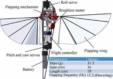
Fig. 1 CAD structure demonstration of NPU-Tinybird.
The shape parameters of flapping wings are selected carefully according to the results of quasi-steady aerodynamic estimation method, rule of scale and experiences obtained from former work. To simplify the structure, the wings only own one single DoF of flapping, while the rotation around the leading-edge during flapping is obtained passively, under the mutual interaction among the aerodynamic forces, the elastic forces from wing membrane and the inertial forces from carbon ribs.Camber angleis the key point to achieve the desired passive rotation of flapping wings.
For the flapping mechanism, a novel motor driven CRMis designed, which converts the rotational input from Direct Current(DC)motor into the reciprocating motion of the wing roots and finally achieves the flapping motion of wings.To further control the attitude, a frame consisting of PHM is combined with CRM, which is able to control the stroke plane angle of each wing and the derivation angle from stroke plane through linear servos.
Based on this kind of stroke plane tilting modulation, an attitude control approach is proposed, as shown in Fig. 2.Pitch-control moment is obtained by simultaneously tilting the stroke plane of each wing forwards or backwards, making the action line of averaging lift over one cycle generate a distance from the Center of Gravity (CG), which is shown as Fig. 2 (a) and (b); Roll-control moment can be created by simultaneously tilting each wing sidewards in the same direction, shown as Fig. 2 (c); Yaw-control moment is created by tilting the stroke plane of left and right parts of wing in the opposite direction, and corresponding illustrations are shown as Fig. 2 (d).
2.2. Coordinate system
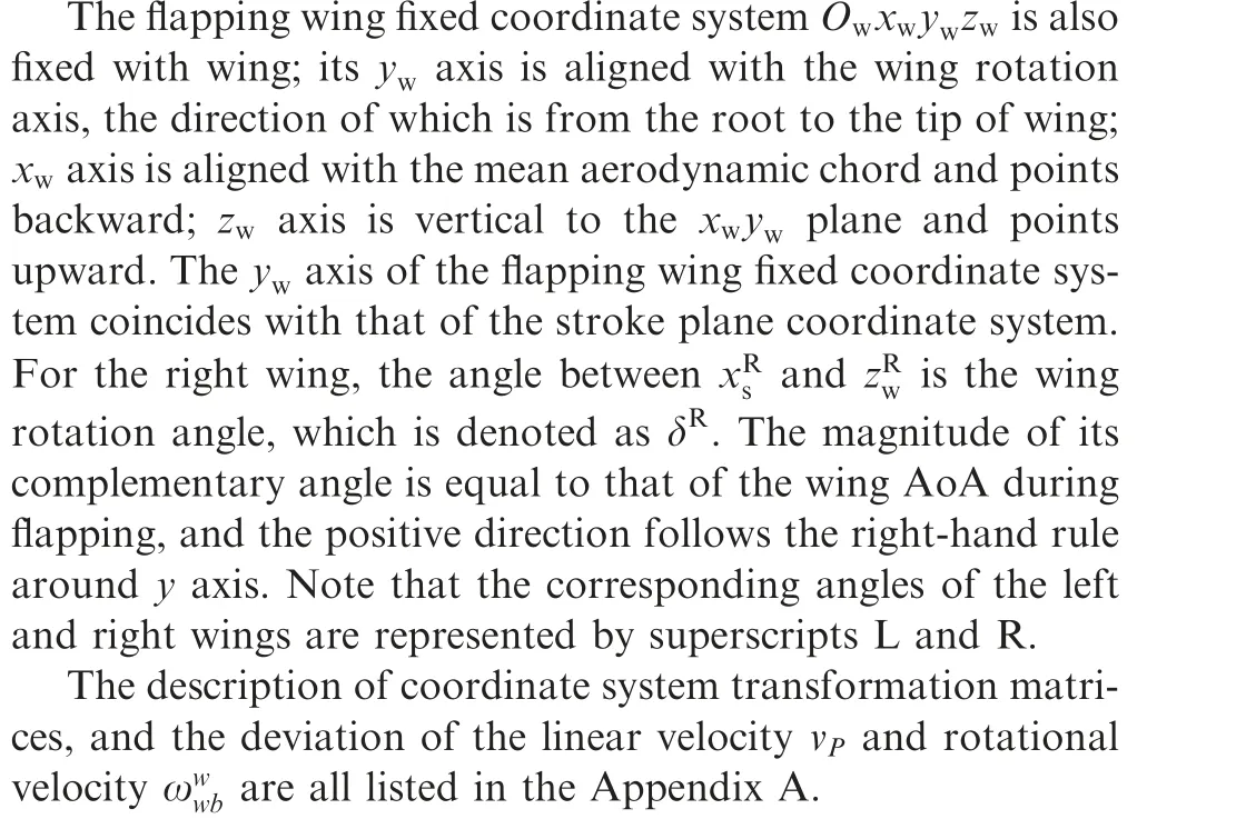
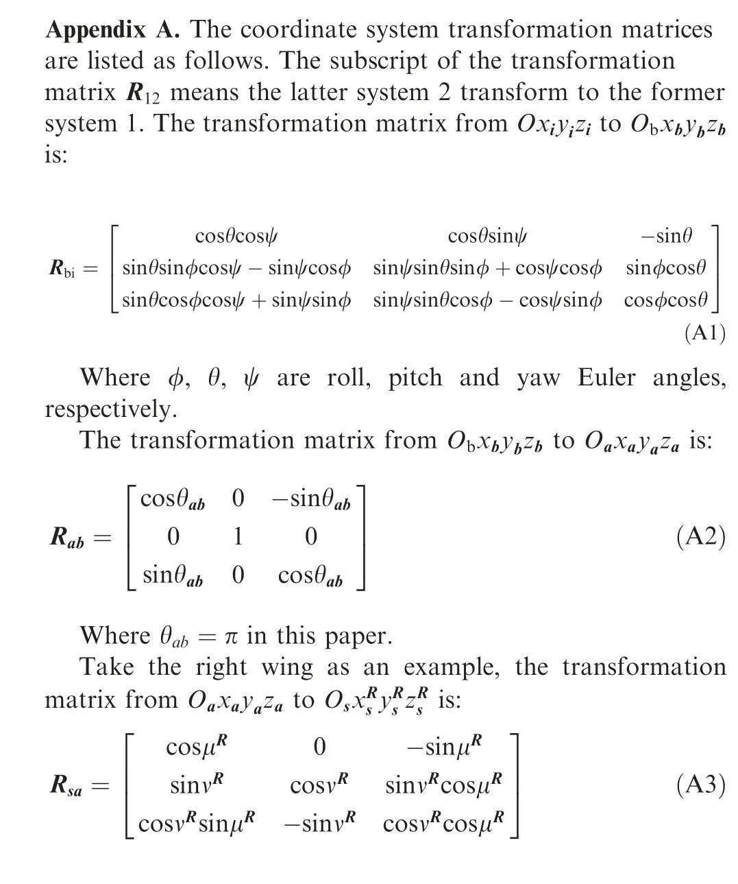
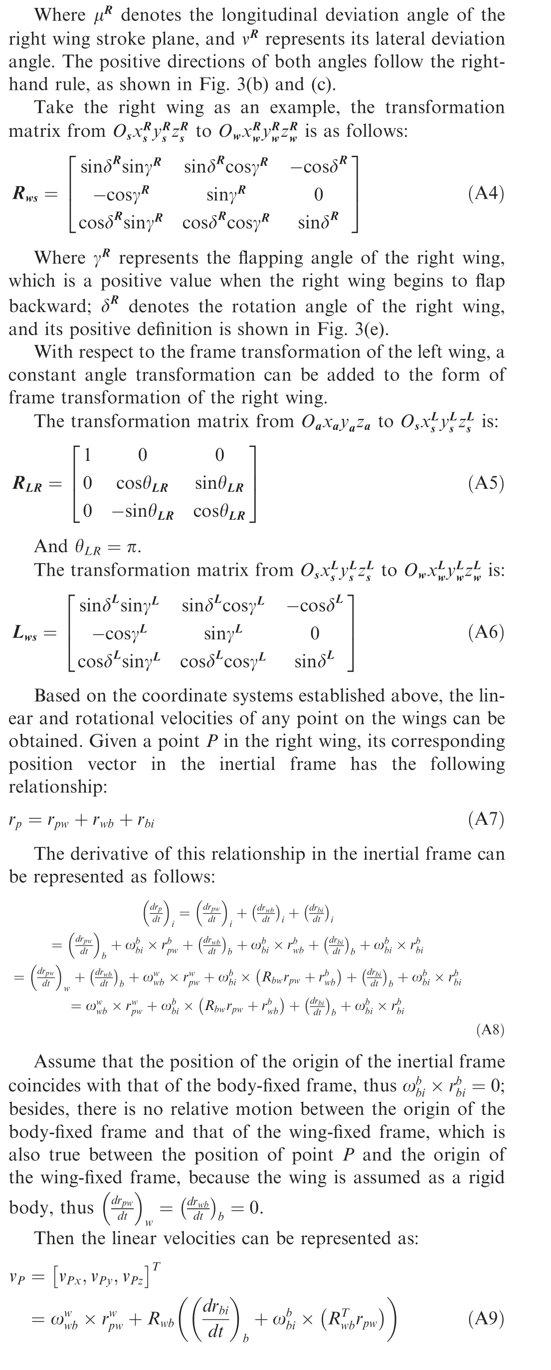
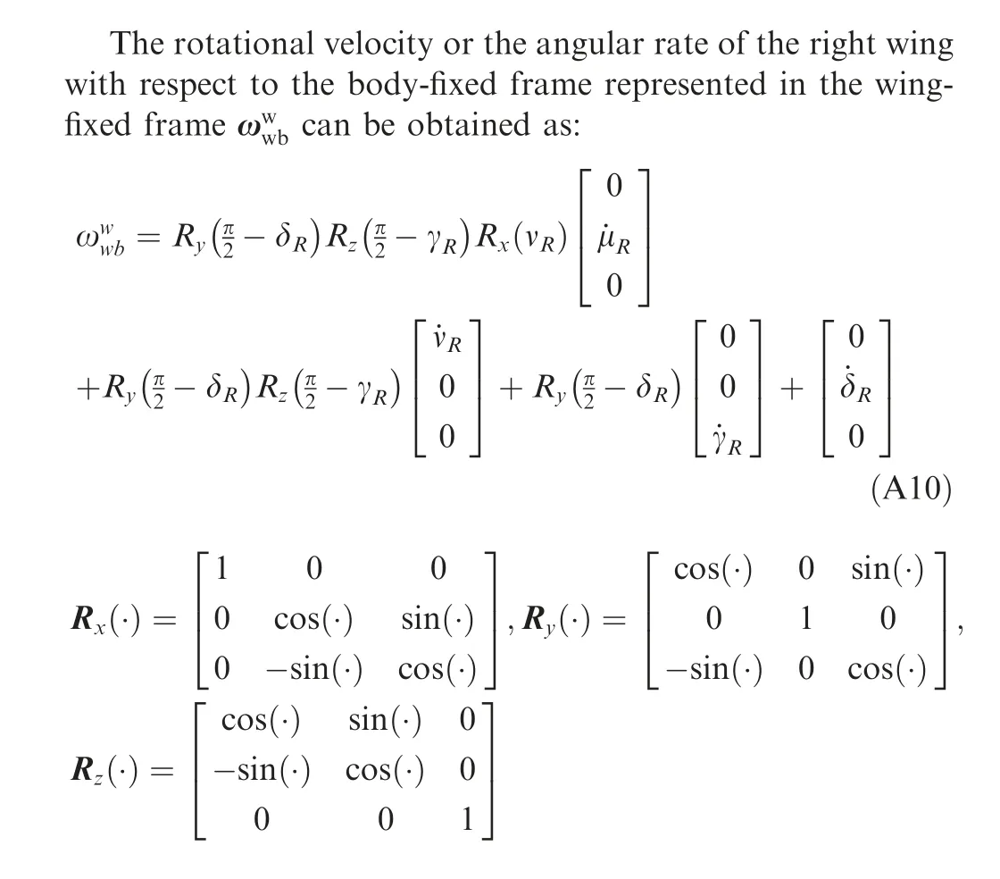
In this paper, five coordinate systems are established to fully describe the dynamic model of NPU-Tinybird,that is,the inertial coordinate system Oxyz, the body fixed coordinate system Oxyz, the aerodynamic coordinate system Oxyz,the stroke plane fixed coordinate system Oxyzand the flapping wing fixed coordinate system Oxyz. The latter two systems between the left and right parts of the wing are different. All these coordinate systems are illustrated in Fig. 3.
The inertial coordinate system Oxyzis fixed to the Earth and uses North-East-Down (NED) coordinates. The body fixed coordinate system Oxyzis fixed to the fuselage frame;origin O and Oare all located at the position of CG;axis vector zpoints downward and is aligned with the longitudinal symmetric line of body; axis vector xpoints forward and is vertical to the longitudinal symmetric line of body axis vector ypoints right, and is vertical to the xzplane, as Fig. 3(a)shows.
The aerodynamic coordinate system Oxyzis used as a reference frame for aerodynamic calculation, origin Ois located at the position of CG.Axis vector xpoints backward and is vertical to the longitudinal symmetric line of body;axis vector zpoints upward and is aligned with the longitudinal symmetric line of body; axis vector ypoints right and is vertical to the xzplane.
The stroke plane fixed coordinate system Oxyzis obtained by firstly rotating the coordinate system Oxyzaround the yaxis (the corresponding angle is denoted by μ);and then rotating the intermediate coordinate system around its × axis (the angle of which is denoted by ν); the positive directions of both μ and ν follow the right-hand rule.
Based on the coordinate system established above, a nonlinear simulation structure of NPU-Tinybird can be constructed, the main structure of which is shown in Fig. 4, all symbols will be explained in the following sections. The nonlinear time-periodic dynamic model consists of an aerodynamic model, a kinematic and dynamic model of flapping wing and attitude control, and a rigid body dynamic model,which will be determined in Sections 2.3-2.5. The wing inertia effect is neglected to simplify the modeling process, which is reasonable because the wing mass of NPU-Tinybird is much smaller than the body mass and simultaneously its flapping frequency is much higher than its natural frequency of body motion. This criterion has been verified and used in some researches, such as the work of Sunand Orlowskiet al.
2.3. Aerodynamic modeling
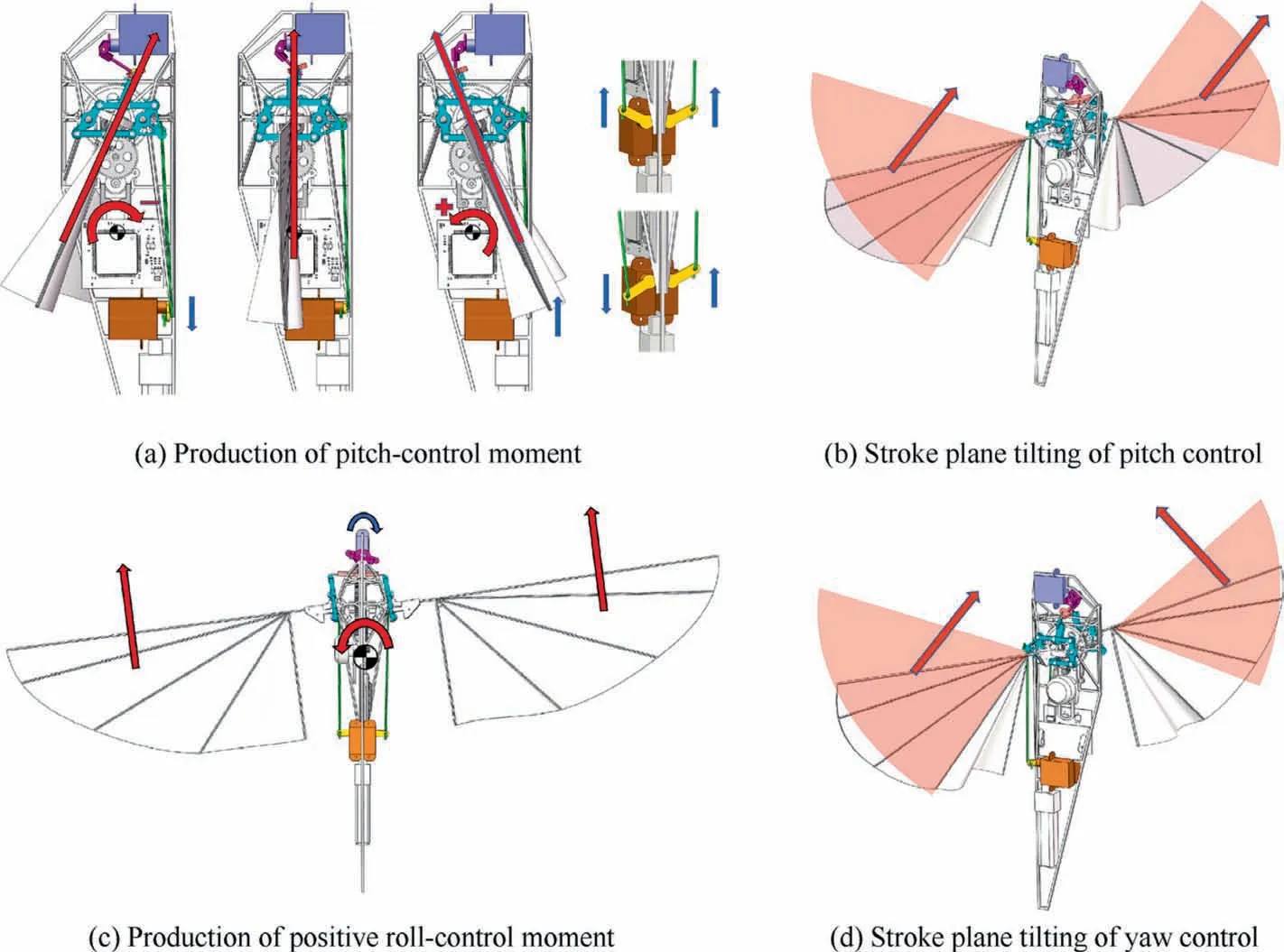
Fig. 2 Details of the attitude control approach and its mechanism.
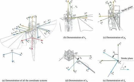
Fig. 3 Definitions of coordinate systems.
As the primary source of both lift force and moments of attitude control, the flapping wing of insect-like tailless FWMAV has many complex unsteady aerodynamic mechanisms, for instance, delayed stall, rotational lift and wake capture,etc.. With regards to the aerodynamic modeling of such mechanisms, there are several methods that have been explored, such as the Computational Fluid Dynamic (CFD)method, linear damping estimation methodand quasi-steadymodifiedbladeelementestimation method.The CFD method has been developed to explore the flight mechanism of flying insects and insect-like tailless FWMAV; however, it usually consumes much time and computing units, which is not suitable for the initial design, the evaluation, or the dynamic simulation of a FWMAV. The linear damping estimation method, which directly models the average aerodynamic forces as linear damping with respect to velocities of body, has been used in the modeling of some FWMAVs, nevertheless, this method can only calculate the average aerodynamic forces and moments, and cannot avoid modeling errors.
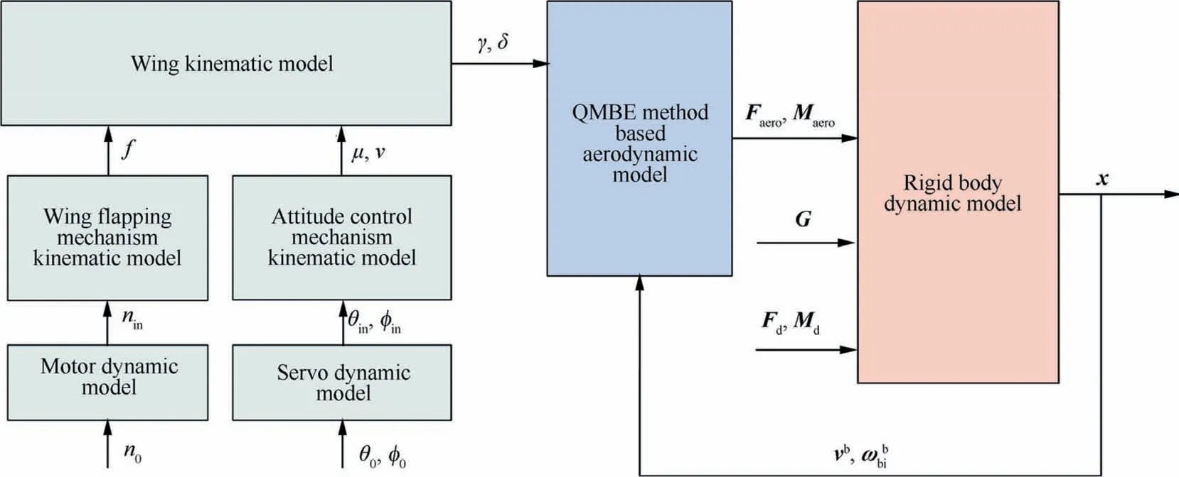
Fig. 4 Nonlinear simulation structure of NPU-Tinybird.
The Quasi-steady Modified Blade Element(QMBE)estimation method has been widely used for the estimation of dynamic model of insect-like tailless FWMAV.This method considers the following typical aerodynamic forces:the wing translational force,the rotational force and the added mass force. The QMBE estimation method has been verified that it can reflect relatively correct variation of the aerodynamic force during a cycle,although deviation still exists compared with the result of the CFD method.In this paper, the aerodynamic model is established by the QMBE estimation method, which is suitable for the analysis and simulation of hovering and near-hovering flight states.
2.3.1. Translational force
The translational force is the major contribution of the total lift and drag forces of the wing, which is produced during the large part of the whole flapping procedure. With regard to the blade units shown in Fig. 5(a), where c and l are the lengths of chord and half span of the wing, the unit translational force can be expressed as follows:
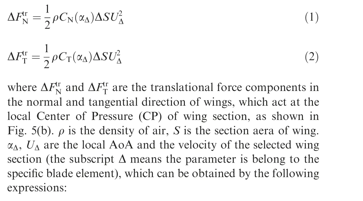
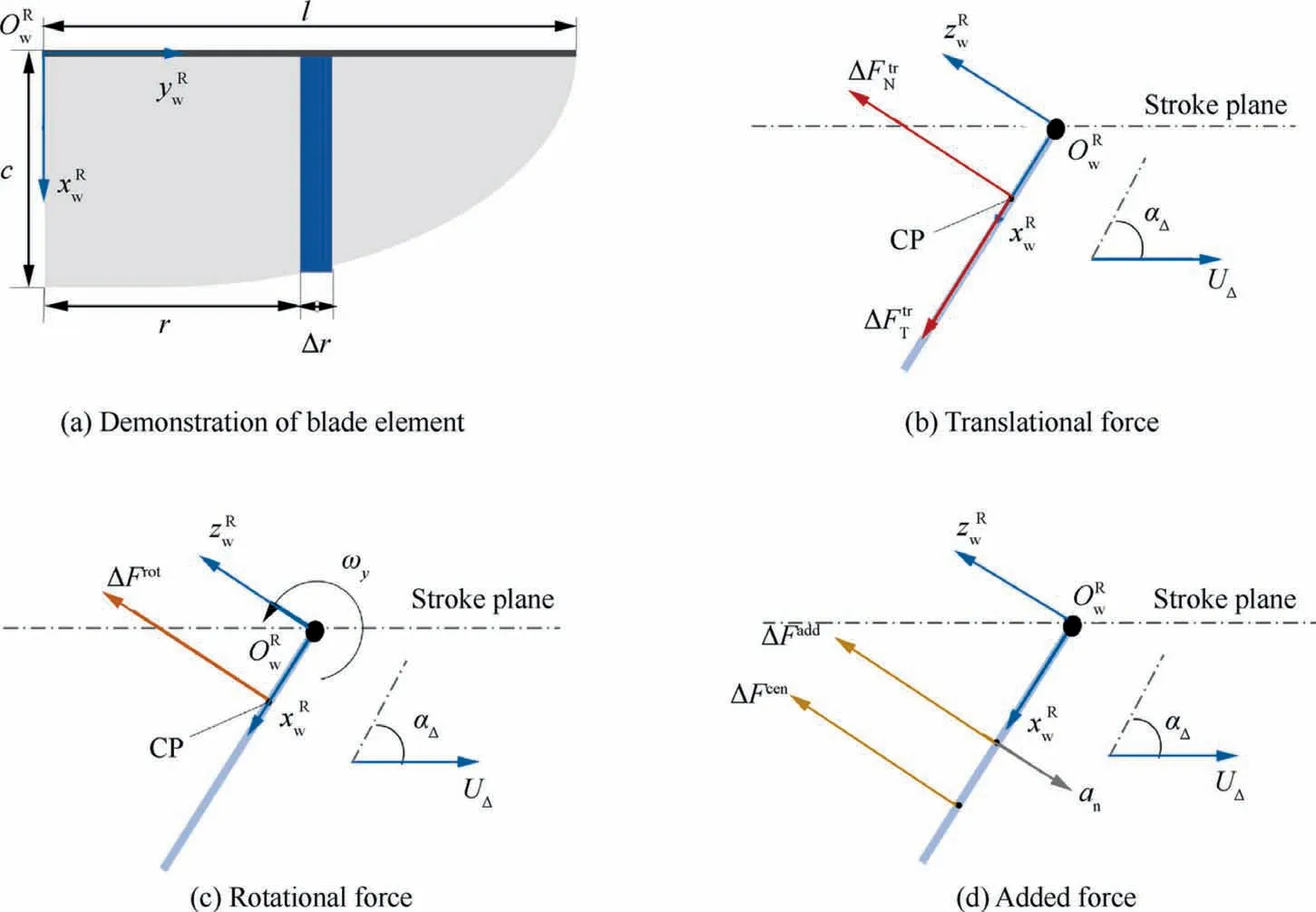
Fig. 5 Demonstration of QMBE method.
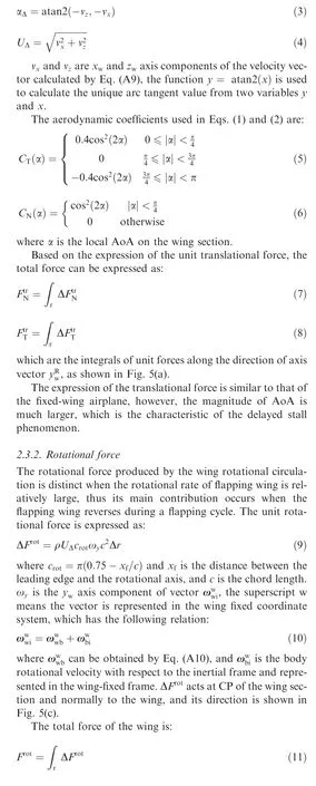
2.3.3. Added mass force
The added mass force exists during the whole procedure of wing flapping, which is the result of the interaction between wings and the air around them when wings accelerate or decelerate. The contribution of the added mass force to the total force is small, thus it is neglected in many works, but in this paper, this force is kept to maintain the accuracy of model.The unit added mass force consists of two parts, that is, the apparent mass acceleration force and the centrifugal force,which can be expressed as follows:

where ais the normal component of acceleration of wing motion, which can be obtained by differentiating Eq. (A9),vdenotes the component of relative wind speed in the chord direction and ˙αis the derivative of local angle of attack of the wing section. ΔFis located at the position of half chord and ΔFacts at 3/4 of the chord from the leading edge, as shown in Fig. 5(d).
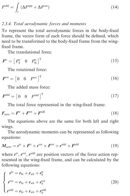
The total force is:


2.4. Flapping and attitude control mechanism modeling
In this subsection, modeling of a novel flapping mechanism and actuators is presented. Firstly, the kinematic model of CRM is established,and the flapping motion function of wing root is derived,which can be used as the final flapping motion function of the whole wing. Based on this, the wing kinematic model is determined. Secondly, the kinematic model of mechanisms for attitude control, that is, PHM mentioned above, is analyzed, which will influence the linear effect of attitude control.
2.4.1. Kinematic modeling of CRM
The flapping mechanism used in the NPU-Tinybird, named CRM, is shown in Fig. 6. In the picture, gears G, G, Gand Gform the gear train which could transfer the rotational torque and movement from the brushless motor to gear crank D.Crank Dalso owns a conical rocker sleeve,just as demonstrated in the picture,which drives rocker Drotates and slides in it, and so they form the rotating sliding pair. Then rocker and wing root Dform the rotating pair. When crank Drotates around axis A,rocker Dwill follow Dto form a conical track,the top of which is located at the intersection of the two axes because flapping axis Ais restricted to the body framework and only has a degree of rotation. As a result,rocker Dwill drive wing root Dto flutter up and down around Aaxis, and the magnitude of the flapping angle is equal to that of the conical top angle of the conical track.Finally, this completes the conversion from the rotational motion of the input power into the flapping motion of the wing.
To model the kinematics of the flapping mechanism,firstly,the speed ratio of the gear train is determined:

where nand nare the rotational speed of the brushless rotor and the gear G; τ, τ, τand τare the number of tips of the gear fixed on the motor shaft Gand gears G,G, G, respectively. Eq. (22) provides the relationship of the input and output gear rotational angles, where Δθand Δθare rotational angles of gear Gand Gper unit time,respectively.
Furthermore,the kinematics of CRM is established,shown in Fig.7.The circle of PPis the rotation locus of gear crank D, named circle O; and the conic surface, the tip of which is located at point Oand the base is circle O, is the area swept by the conical rocker during motion. Define that the radius of circle O is R, and the distance between point Oand point O is D. In this way, the magnitude of the flapping angle can be obtained by the following equation:

Accordingly, assume the angular velocity of Gis denoted as ω, the rotational direction of which is anticlockwise and the flapping angle begins to be positive when the crank passes point P, as shown in Fig. 7. Thus, the kinematics of the flapping motion can be modeled as:

To verify the kinematics above, a simulation of kinematics is designed based on the CAD model of NPU-Tinybird. The results are shown in Fig. 8. In this figure, t is time and T is the period of flapping, and the result demonstrates that Eq.(24)can be seen as a good proximate expression for the motion of wing flapping. And based on this, the kinematic model of wing can be obtained.
2.4.2. Kinematic model of wings
The insect-like tailless FWMAV is expected to own 3DoF wing kinematics to simultaneously produce lift force and control the attitude, that is, the wing flapping motion, wing rotation motion and wing deviation motion, which mimics the ability of its nature counterpart.Besides,there are also several wing kinematic parameters that can change the shape or pattern of motion.By combining those patterns of wing kinematic parameters, one can always find an effective combination to control the attitude. In this subsection, the kinematic functions of wing flapping and wing rotation are determined,and the wing deviation motion is neglected,based on which the attitude control pattern and its model with wing stroke plane tilting are established in Section 2.4.3.
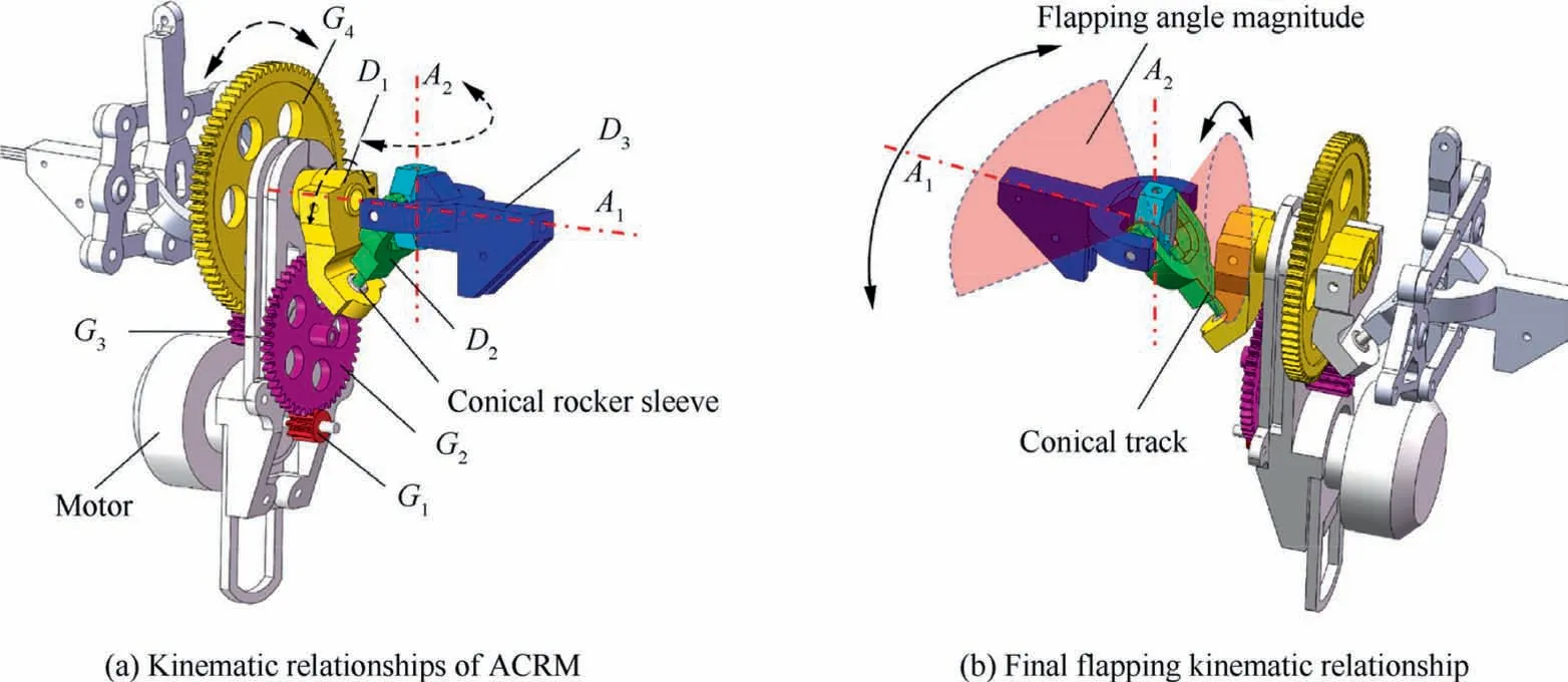
Fig. 6 Main structure of ACRM.
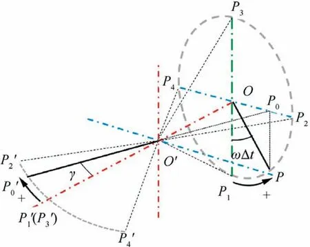
Fig. 7 Kinematic demonstration of CRM.
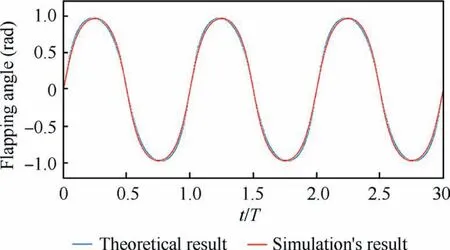
Fig. 8 Comparison of theoretical and simulated results.
Based on Eq. (24),the kinematic function of the wing flapping motion is given:
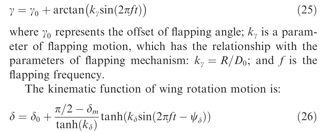
where δrepresents the offset of rotation angle;δdenotes the magnitude of rotation angle;kis the shape parameter of rotation motion of wing;and ψrepresents the phase shift between the wing flapping and the rotation motion.
The parameters of these motion functions such as γ,k,δ,δ, kare selected from the overall design of NPU-Tinybird and the optimization of the lift force and attitude control moments is also considered. The specific values of these parameters are listed in Table 1. In addition, Fig. 9 shows the shape of the kinematics of wing flapping and rotation.
2.4.3. Kinematic modeling of attitude control mechanisms
Attitude control mechanisms of NPU-Tinybird are demonstrated in Fig.10.The main component of the attitude control mechanisms is the PHM, denoted by L, and it is a parallelo-gram hinge framework made of carbine fiber component material, which is able to rotate around axes Aand A, driven by the according servos. Then the stroke plane of left and right wings will tilt for certain angles, which will produce the 3DoF attitude control torques.

Table 1 Design parameters of NPU-Tinybird.
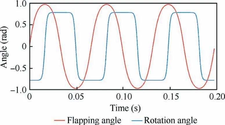
Fig. 9 Shape of wing flapping and rotation function.
As mentioned in Section 2.1, to obtain a positive or negative pitch attitude control torque,the outputs of servos located at the belly of fuselage need to simultaneously deflect by the same angle upwards or downwards, which makes the stroke plane of left and right wings tilt backwards or forwards.Accordingly, a yaw attitude control torque can be obtained by tilting the stroke plane of left and right wings in the opposite direction,which needs the belly servos deflect in the opposite direction.
To achieve the procedure mentioned above, take the left wing control mechanism shown in Fig. 10 as an example:firstly servo Ldrives the arm of servo Lto deflect by angle θ(positive when deflecting upwards and negative when deflecting downwards), which will be transformed by the connecting bar Lto drive the PHM to rotate the same angle around axis A; and thus the relationship between the tilting angle of stroke plane and the output of servo can be determined:

Similarly, a roll attitude control torque can be achieved by the deflection of the head servo,which will make the PHM tilt around axis A.The corresponding kinematic procedure is that firstly head servo Ldrives the arm of servo Lto deflect by angle φ,the value of which is defined as positive when rotating towards the right wing and negative when towards the left.Because hinge Land servo arm Lform a rotating sliding pair, angle φis transformed to the translation movement of hinge L, which will finally drive the PHM to rotate around axis A. Consequently, the kinematic model of roll control mechanisms can be described as follows:
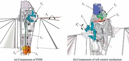
Fig. 10 Demonstration of attitude control mechanisms.
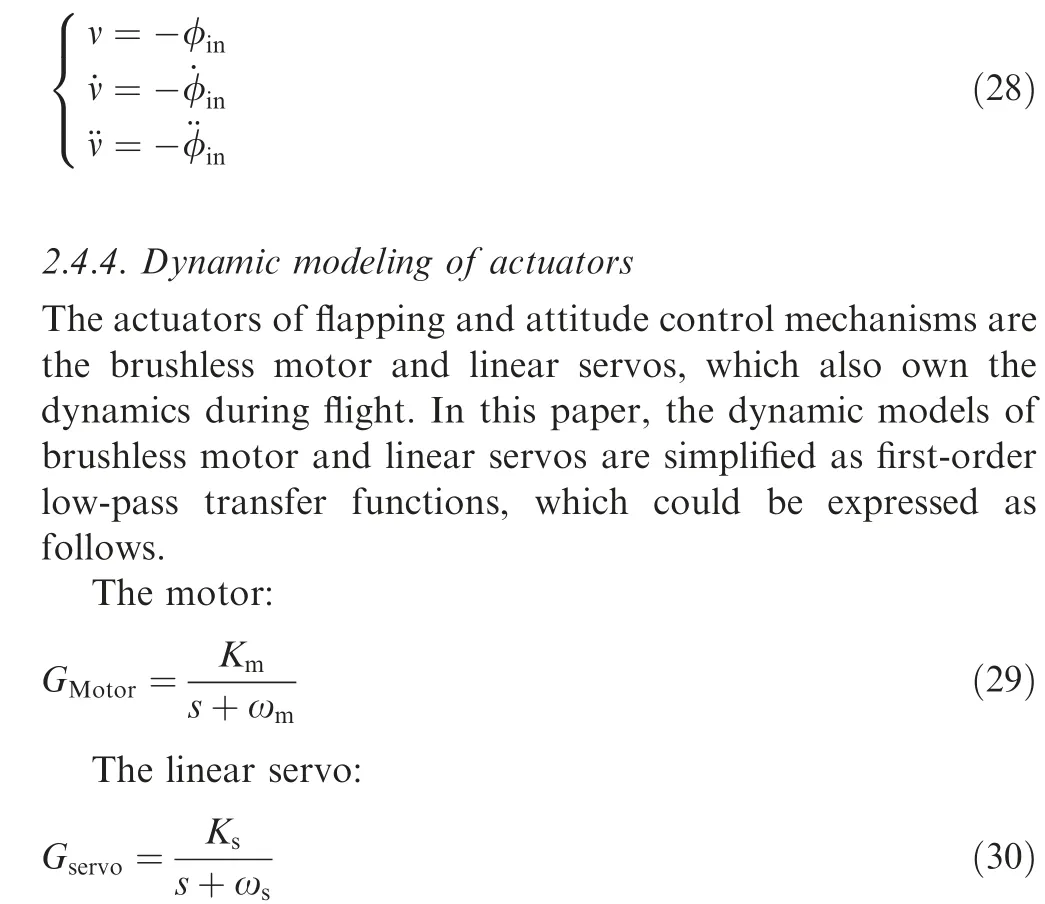
where K, ω, Kand ωare dynamic parameters of motor and servos,which are obtained according to the overall design of NPU-Tinybird and dynamic experiments, s is the independent variable of complex frequency domain. The parameters and their values are listed in Table 2.
The Bode plots of Eqs. (29) and (30) are shown in Fig. 11.In the picture, the cut-off frequencies of motor and servos are 48 rad/s and 32 rad/s, respectively.

Table 2 Parameters of dynamic system of motor and servos.
2.5. Body dynamic modeling
In this subsection, the rigid body dynamic model is discussed,based on which the final nonlinear time-periodic model of NPU-Tinybird is obtained.
Firstly, the dynamic model can be obtained through Newton-Euler Equations for the single rigid body object,which is listed as follows:
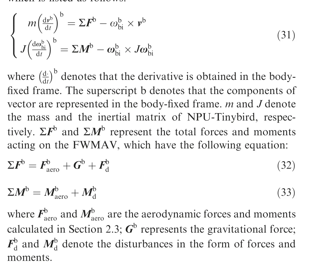
Due to the periodic property of aerodynamic forces and moments, Eqs. (31), (32) and (33) construct a nonlinear timeperiodic dynamic model. Besides, based on the modeling above, a high-fidelity simulation towards the nonlinear dynamic model of NPU-Tinybird can also be established.
2.6. Model linearization and analysis

Fig. 11 Bode plots of motor and servo.
The model established above is a nonlinear time-periodic one which is hard to handle and analyze. In order to simplify the complex dynamic model and reflect its major properties,a procedure of model linearization should be conducted. The most complex part of the dynamic model is the aerodynamic model,which is a nonlinear one and outputs the time-periodic aerodynamic forces and moments. A common method of linearization for this issue is the aerodynamic derivatives method,which aims at estimating the major aerodynamic derivatives of the corresponding linear cycle-averaged dynamic model.This method is relatively simple; however, it cannot directly obtain the final linearized dynamic model,because other parts of the dynamic model are not considered,and it cannot reflect the level of model uncertainty or model error due to linearization.
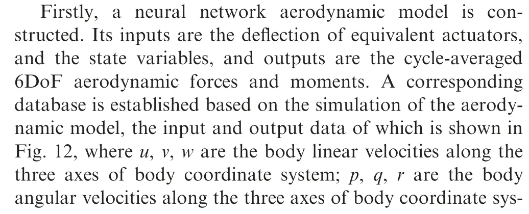
In this paper, to better utilize the established high-fidelity nonlinear dynamic model and fully describe the dynamic characteristics,an estimation method,combined by neural network fitting and system identification is introduced.The function of neural network fitting is to simplify the nonlinear time periodic aerodynamic model and transfer it into a nonlinear cycleaveraged one; and then the method of system identification is used to obtain the linearized cycle-averaged dynamic model.This kind of method is not only able to simplify the aerodynamic model and reflect the boundary of model error,but also to offer the possibility of fusing more aerodynamic data from other types of technology,such as the wind tunnel experiment or CFD technology in future works.

The inputs of neural network are given around the state of hovering,as shown in Fig.13.In the picture,data of inputs are all divided by the maximum value and represented as normalized ones.Besides,the distribution of them is not a totally linear one;the closer to the hovering state,the more data need to be collected.Subsequently,a parallel calculation method is utilized to accelerate the simulation and collection of data.
The raw data of outputs are time periodic,which should be transferred into the cycle-averaged form before used by the neural network training.
Based on the aerodynamic database established above, a two-layer neural network aerodynamic model with 10 hidden neurons is obtained which is trained by Levenberg-Marquardt training method. The mean squared error of the method between the outputs and targets is below 2.9×10,and regression R value is larger than 0.99994, which indicates the good quality of fitting result.
Then a neural network based nonlinear time-invariant dynamic simulation is determined, based on which a final linearized dynamic model can be obtained through the system identification towards the equilibrium state of hovering. Take the longitudinal pitch dynamic model as an example, the linearized dynamic model is expressed as:

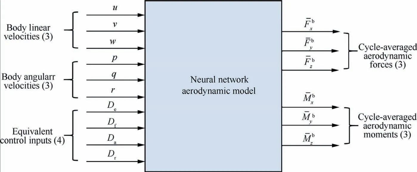
Fig. 12 Inputs and outputs information of neural network aerodynamic model.
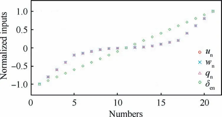
Fig. 13 Normalized inputs of neural network aerodynamic model.
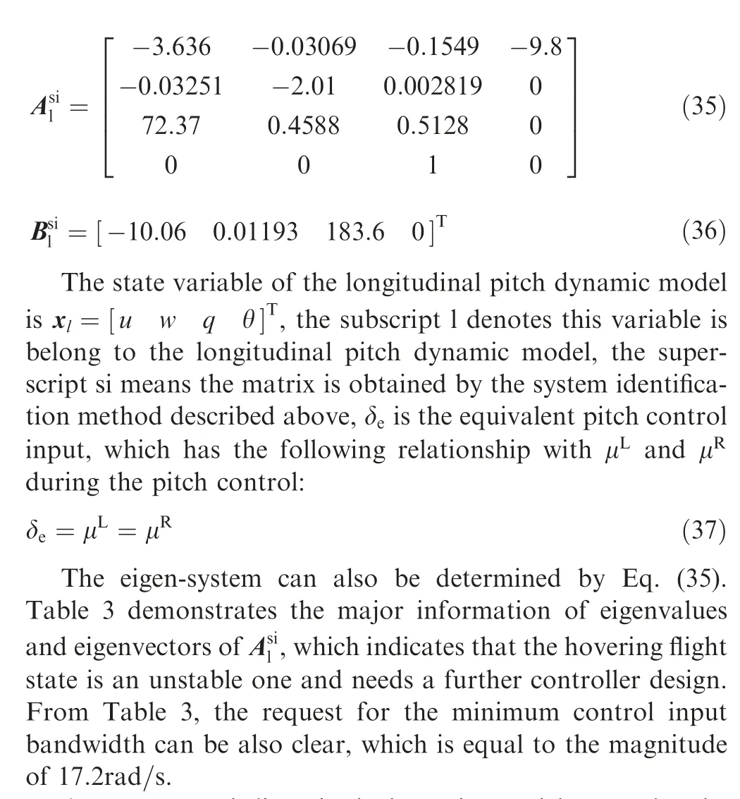
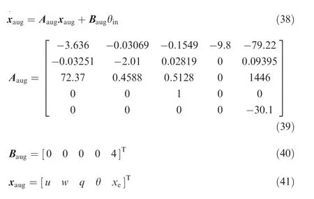
An augmented linearized dynamic model can also be obtained through the method above, when considering the kinematic and dynamic characteristics of the flapping mechanism and attitude control mechanism. For the longitudinal pitch dynamic system, the dynamics of belly servos should be considered.
Assume that xis the state variable of dynamic system of belly servos, considering the kinematics of the belly servo Eq. (27) and transfer function Eq. (30), the augmented linearized dynamic model of the longitudinal pitch control system can be expressed as follows(the subscript aug denotes the variables belong to the augmented linearized dynamic model):
3. Flapping vibration suppression analysis
In this section, the problem of flapping vibration and the corresponding algorithm of suppression are investigated. Firstly,details and adverse influences of the flapping vibration for the flight of tailless FWMAV with the stroke-plane tilting attitude pattern are described. Then a novel Kalman based state observer named FVSO is designed, which can suppress the influence of flapping vibration and estimate near cycleaveraged state variables. To verify the FVSO, a closed loop simulation is established based on a robust Linear Quadratic(LQ)optimal control algorithm,and furthermore,several classic suppression algorithms are designed to compare their effects of suppression.
3.1. Flapping vibration phenomenon and classic methods of reduction
3.1.1. Flapping vibration phenomenon and its influence
Flapping vibration is a common phenomenon which exists in the flight procedure of all types of tailless FWMAV.The origin of this phenomenon is the flapping motion of its wings, which produces the time-periodic aerodynamic forces and moments,and consequently the time-periodic vibration of all flight state variables. Flapping vibration can be seen as a time-periodic noise appearing everywhere of the closed loop when compared with its cycle averaged counterpart: firstly, it can be captured by sensors during flight and enters into the flight controller through the feedback loop; then it appears in the control outputs to the actuators; finally, it returns to the flight dynamics of FWMAV. Although one can obtain a time-invariant dynamic model when analyzing models and designing controllers, this kind of flapping vibration still exists during the real flight procedure, causing several adverse influences onthe flight of FWMAV,especially on those which use the stroke plane tilting as the attitude control pattern,and NPU-Tinybird is one of typical examples.A detailed analysis about its adverse influences is described in Appendix B.

Table 3 Information of eigen-systems.
3.1.2. Classic methods to reduce the influence of flapping vibration
There are several ways to reduce the negative influence of flapping vibration,that is,classic low pass filters in the feedback or feedforward loop, observers in the feedback loop, or special controllers in the feedforward loop that can reduce the flapping vibration. However, some phase shifts will appear when utilizing the low-pass filter in the feedback or feedforward loop, which will degrade the robustness and change the dynamic performance of the system.That is because the classic low-pass filters were originally designed for the electronic circuits and did not consider the characteristics of the dynamic model, thus their phase shifts were not specially optimized.To improve this kind of situation, some special controllers or observers should be designed based on the characteristics of dynamic model. The classic Kalman filter, which was firstly developed in 1960 s,has achieved a good performance in many applications, such as navigation, guidance and control of aircraft and spacecraft.It utilizes the control inputs and the measurements of model outputs to estimate the states variables of the dynamic model,and to simultaneously calculate the estimated covariance matrix; eventually, it can achieve the least quadratic estimation of the state variables under the assumption that the process and measurement noise is a white one.However, the shortcoming of classic Kalman filter is distinct when dealing with the flapping vibration, which cannot be treated as a white noise.
Recent years,researches about the vibration control of flexible wings of bird-like FWMAV are also excellent,many novel control schemes are designed to suppress the vibration of the flexible wing,such as boundary controland iterative learning control,however, due to the limited payload and controller performance of insect-like FWMAV, it is still difficult to achieve these control schemes on the insect-like FWMAV.
3.2. Design of FVSO
In this subsection, a Kalman based FVSO is designed to suppress the flapping vibration. The main function of this FVSO is to estimate the relatively steady state variables by using the control inputs and system outputs data. Through the observation of FVSO, the controller can directly deal with the steady state data instead of oscillated ones. FVSO, which is designed for the flapping vibration, is better than the classic Kalman filter, the H-infinity filter and the low pass filter,which will be verified through the simulation later in this paper.
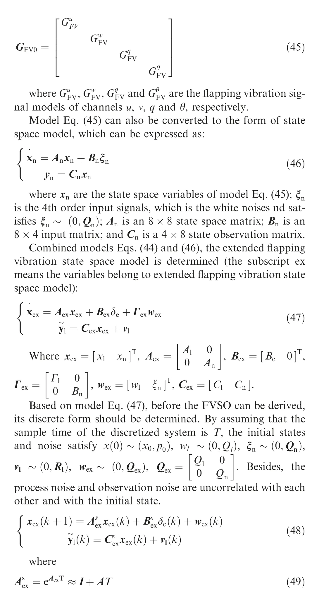
To design a FVSO,a noise dynamic model representing the major characteristics of the flapping vibration signal should be determined. To achieve this, the Power Spectrum Density(PSD) of typical flapping vibration signals in the main channels of NPU-Tinybird should be analyzed. With this noise dynamic model,an extended state observer is established based on the Kalman filter.Therefore,FVSO uses the characteristics of both the flapping vibration and the dynamic model of NPUTinybird.
3.2.1. Flapping vibration dynamic model
The flapping vibration signal can be separated out by comparing the original signal and the corresponding cycle-averaged one, which can also be seen as a separation of the steady and oscillated components of the original signal.Subsequently,a PSD analysis can be made to obtain the major characteristics of flapping vibration signal in every channel of the model.Fig. 14 shows the PSD analysis results of the longitudinal channel signals.
Then a second-order band-pass noise dynamic model is used to represent the major characteristics of the flapping vibration signals, and its expression is (The subscript FV means flapping vibration):

The meaning of this model is that, the flapping vibration signal can be seen as a filtered signal from a unit white noise which is filtered by this band-pass filter.
And the following relationship should be maintained:

where χ(x) denotes the PSD of θ;q;u and w signals from the longitudinal pitch dynamic model. Table 4 demonstrates the meaning and magnitude of corresponding symbols.A comparison of the PSD of flapping vibration signal and the bode magnitude plot of band-pass filter is also shown in Fig. 14. The units of PSD depend on the type of signals, for instance, the unit of signal θ is rad/(rad/s).
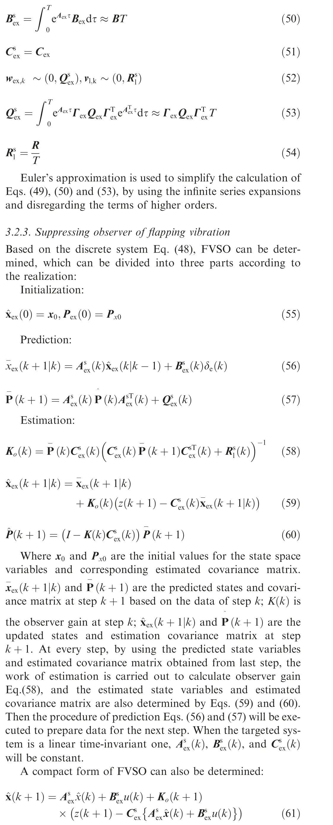
3.2.2. Extended state model
To obtain the FVSO, a Single-Input and Multi-Output(SIMO) longitudinal pitch dynamic model considering noises and flapping vibration is given to provide further description:

Where wis the process noise;Γis the corresponding noise input matrix; Cis a 4×4 identity matrix; yand vare the flapping vibration and observation noises; and y~l denotes the oscillated output signals of system.
Because there are four channels of output signals, each of them is influenced by the flapping vibration,and thus the total noise dynamic model of flapping vibration is a 4th order one:
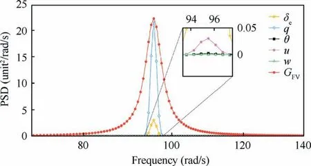
Fig. 14 PSD analysis of longitudinal pitch dynamic signals and the magnitude of filter.
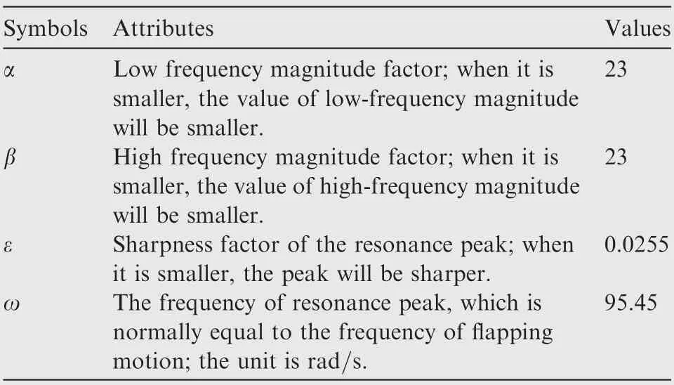
Table 4 Main parameters of filter GFV
3.3. The closed loop control simulation
To further discuss the closed-loop stability and dynamic performance, a state feedback control framework is established using the robust LQ optimal algorithm and the vibration suppression observer described above.
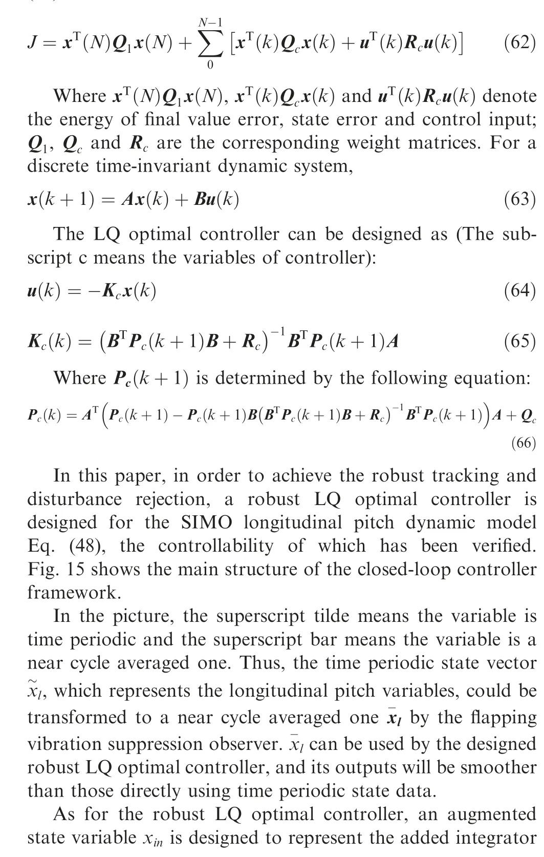
The LQ optimal controller,which is a fundamental optimal state feedback controller, aims to minimize the cost function consisting of state error and control effort, as shown in Eq.(62).
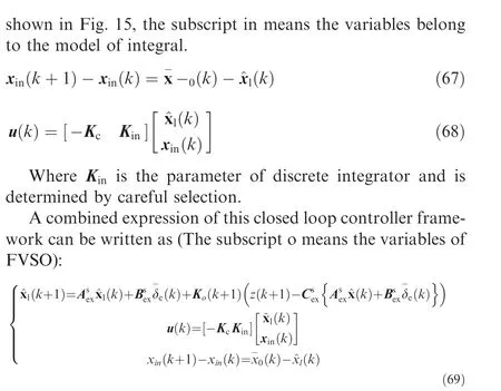
where Kand Kare determined by Eqs. (58) and (65),respectively.
4. Simulation results
In this section, simulation results are obtained to verify the performance of the designed FVSO by comparing with other methods of state observation and vibration suppression, such as the classic Kalman filter, H-infinity filter and the classic low-pass filter. To do this, the stability and dynamic performance of the closed loop controller should be maintained,which will be firstly demonstrated.
4.1. The responses of initial states
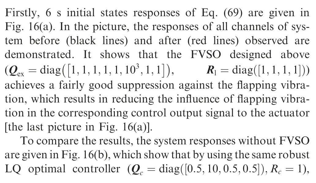
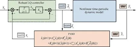
Fig. 15 Demonstration of closed loop controller framework.
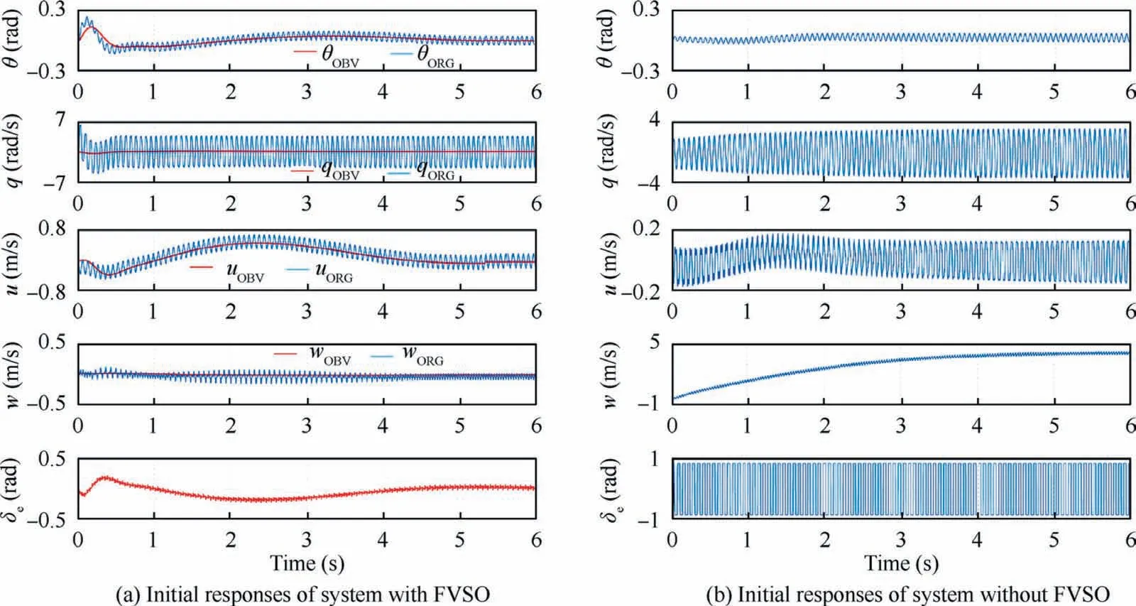
Fig. 16 Comparison of initial states responses of system with and without FVSO.

4.2. The responses of step input
10 s step responses of the system with(in Fig.17(a))and without FVSO (in Fig. 17(b)) are also presented. The reference input is the forward body velocity with a magnitude of 0.3m/s. To achieve this, the FWMAV should firstly produce an acceleration along the positive direction of xaxis of the body frame, which needs a negative magnitude of the pitch angle; when the reference is obtained, the pitch angle should return to the states of equilibrium, as shown in the first and second pictures of Fig. 17(a). Controlled by the same robust LQ optimal controller (Q=diag([0.5;10;0.5;0.5]);R=1),the response of forward speed of the system using FVSO [the third picture of Fig. 17(a)] can reach the desired value in 10 s, with other states stabilized.
The system without FVSO can also achieve the acceleration of the forward speed, however, the whole procedure lasts a long time which exceeds 20 s. Besides, its control input signal is still a saturated one, and the lift forces is reduced,as shown in Fig. 17(b).
4.3. Parameter tuning of FVSO
To design a proper FVSO,there are several parameters should be considered, including the parameters of Gand twelve parameters in Qand R, which seems complex. However,there are also skills or tuning laws that can simplify the design procedure of FVSO.
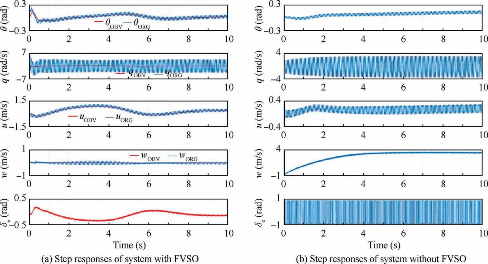
Fig. 17 Comparison of step responses of system with and without FVSO.
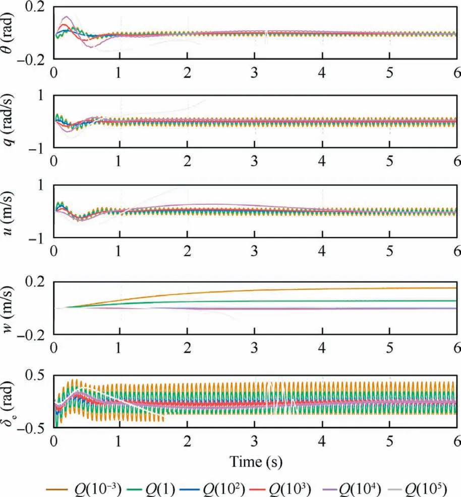
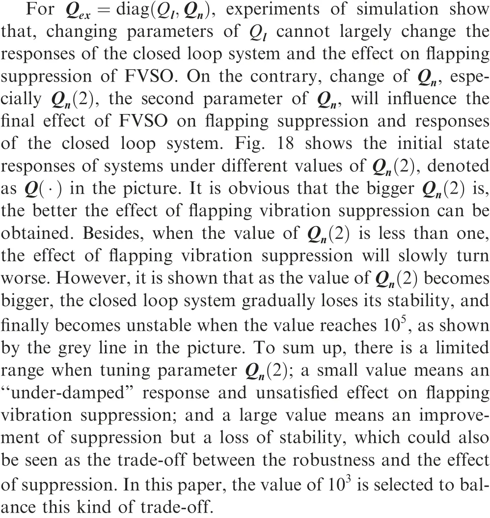
Fig. 18 Comparison of initial state responses of systems with different parameters.

For Qand R, similar to other optimal controller and observer,their parameters can be tuned according to the information of noises. Besides, if the information of process and observation noises is not enough, the actual responses of the closed loop system should be used to help the tuning of parameters. When adjusting the parameters of Qand R, the method of relatively tuning can be used, which keeps Rconstant and just changes parameter values of Q,due to the relative relationship between Qand R.
4.4. Comparison with other filters
A comparison of initial states responses with a Kalman filter,an H∞filter and a 2nd low-pass filter with the cut-off frequency of 10 Hz is also designed to verify the performance of VFSO, under the same conditions of the closed loop simulation.
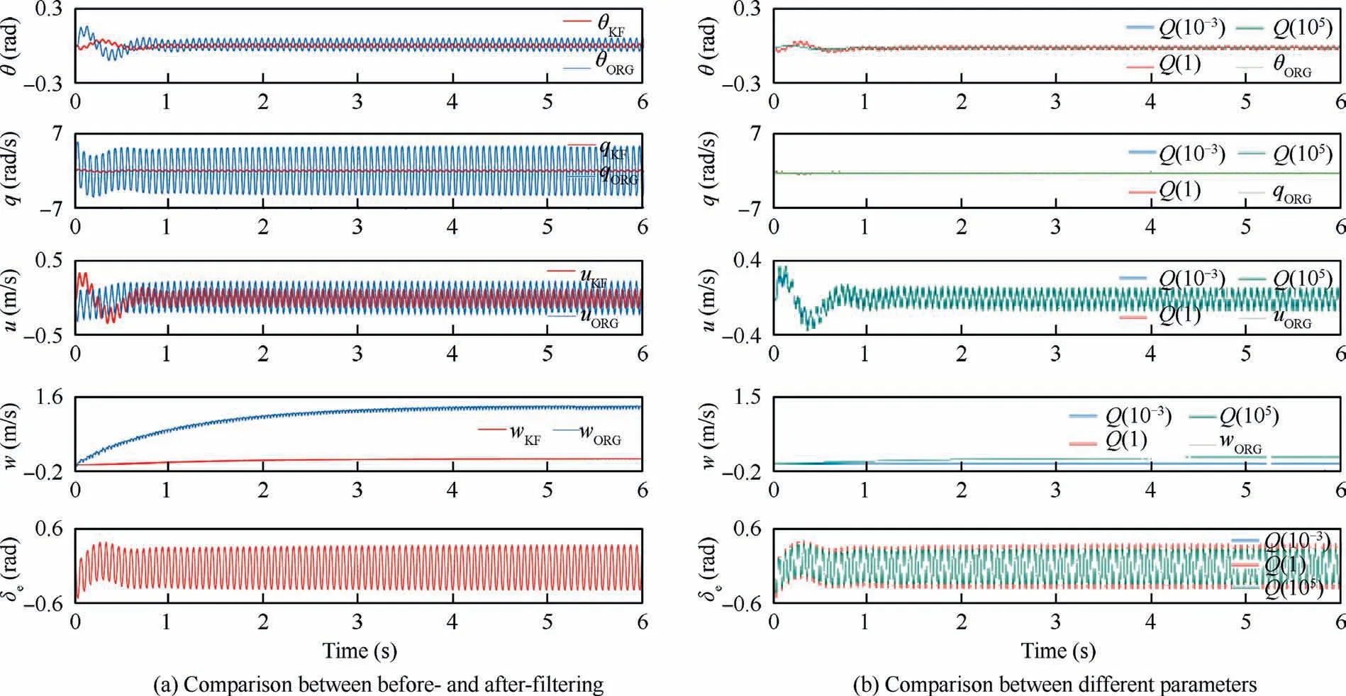
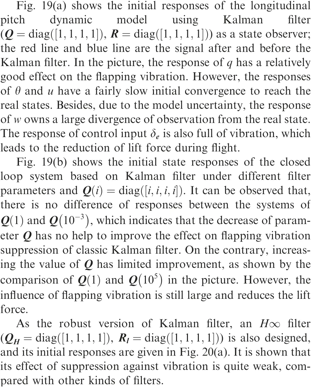
Fig. 19 Initial states responses of Kalman filter based system.
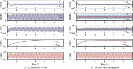
Fig. 20 Initial states responses of H∞filter based and low-pass filter based systems.
The low pass filter is frequently used in the FWMAV controller design to reduce the influence of flapping vibration. In this paper, a 2nd discrete time Chebyshev low pass filter with the cut-off frequency of 10 Hz is designed, and its magnitude at the frequency of 15.2 Hz is - 19 dB and the phase is-157.8.
Fig. 20(b) demonstrates the initial state responses of the closed-loop system using the designed low pass filter as a simplified way to filter the flapping vibration.It is shown that after filtered by the low-pass filter, the influence of flapping vibration is reduced in certain degree, however, the overall effect is weaker than those of FVSO and Kalman filter. Besides, a relatively large phase lag exists in all responses, which coincides with the characteristic of phase lag about the low pass filter and will destabilize the overall closed-loop system.
5. Conclusions
This paper has established a high-fidelity nonlinear timeperiodic dynamic model for NPU-Tinybird,a novel FWMAV.Based on this, a MISO linearized longitudinal pitch dynamic model is constructed by neural network fitting and system identification methods. Its state of hovering is unstable and should be stabilized by the closed-loop controller.To improve the flight performance and control efficiency, a novel state observer, named FVSO is designed and analyzed. FVSO observes oscillated state variables and outputs the near cycleaveraged ones,and thus reduces the effect of flapping vibration in the feedback path of the closed-loop control framework.Through the work presented above,several key points can also be summarized as follows:
(1) For the dynamic modeling of the insect-like FWMAV,the trade-offs between accuracy and computational complexity should be made, such as those during the aerodynamic modeling.The QMBE method used in this paper can be a good choice for dynamic analysis and controller design during the initial phase development of our FWMAV. In the future work, more accurate methods of aerodynamic modeling such as the surrogate-based method will be exploited for the model-based robust controller design.
(2) Flight controllers and observers should be carefully designed, due to the unique dynamic characteristics of the insect-like FWMAV,such as the unstable flight state of hovering and the flapping vibration. The closed-loop control framework of FVSO and the robust LQ controller designed in this paper can be a good reference.Simulation results show that, by using FVSO and the robust LQ controller, the settling time of the attitude inner closed-loop system is less than 1 second,while that not using the framework gradually diverges.Besides,the comparison with other filters shows that, with the same parameters, FVSO can reduce at least 80% of flapping vibration, while the best result of other filters is 50%.
(3) Based on the high-fidelity nonlinear time-periodic dynamic model and FVSO established in this paper,our future work will also focus on the analysis of the lateral dynamic system of NPU-Tinybird and the corresponding robust controller.
The authors declare that they have no known competing financial interests or personal relationships that could have appeared to influence the work reported in this paper.
The authors would like to thank the financial support of the projects from National Key Research and Development Program of China (No.2017YFB1300102), National Natural Science Foundation of China (Nos.11872314 and U1613227),and Youth Program of Natural Science Basic Research Plan in Shaanxi Province of China (No.2019JQ-394).
Appendix B. The adverse influences of flapping vibration are listed as below:
(1) The lift produced by the wing during flapping will be reduced. The outputs of actuators are influenced by the flapping vibration, and the corresponding direction of the stroke plane vector controlled by the actuator outputs is also an oscillated one, causing zaxis component of the lift against the gravity is less than the total magnitude of themselves.
(2) The control inputs of actuators can easily enter the state of saturation.The flapping vibration will make the control inputs an oscillated one,the maximum magnitude of which is near the limitation of input actuators.When the input signal changes at some extent due to the need of attitude control, the whole signal could easily reach the boundary of actuator limitation.
(3) The stabilized equilibrium states maintained by the closed loop controller can be easily broken due to a large magnitude vibration of control input. Many closed loop controllers based on the linear control theory can only stabilize the system in a bounded flight state, and a large state variation caused by the oscillation of control inputs may exceed the state range that the linear controller can maintain.
(4) The control energy will be large. The unnecessary oscillation of control inputs towards actuators due to the flapping vibration is a waste of energy, which needs to be reduced, especially for the FWMAV with limited capacity of battery.
