
Experimental investigation of the full coverage film cooling effectiveness of a turbine blade with shaped holes
2022-03-25 04:23:28CunlingLIUFnZHANGShuiqiZHANGQingqingSHIHuiSONG
Chinese Journal of Aeronautics 2022年3期
Cunling LIU,Fn ZHANG,Shuiqi ZHANG,Qingqing SHI,Hui SONG
a School of Power and Energy, Northwestern Polytechnical University, Xi’an 710129, China
b Shaanxi Key Laboratory of Thermal Sciences in Aero-engine System, Xi’an 710129, China
c Beijing Institute of Radio Measurement, Beijing 100854, China
KEYWORDS Adiabatic film cooling effectiveness;Film cooling;Shaped holes;Turbine blade;Turbulence intensity
Abstract The film cooling effectiveness of two turbine blades at different turbulence intensities(0.62% and 16.00%) and mass flux ratios (2.91%, 5.82%, 8.73% and 11.63%) is studied by using the Pressure-Sensitive Paint (PSP) measurement technique. There are a baseline and an improved turbine blade in current work, and their film cooling hole position distribution is the same. But the hole shape on suction surface and pressure surface is changed from cylindrical hole (baseline)to laid-back fan-shaped hole (improved blade). Both blades have 5 rows of cylindrical holes at the leading edge and 4 rows of cooling-holes on the suction surface and the pressure surface.The experimental results show that the film cooling effectiveness of the improved blade is much better than the baseline.The increase in turbulence intensity will reduce the cooling effectiveness on the surface of turbine blade, but the effect of turbulence intensity becomes weaker with an increase in the mass flux ratio. Compared with the multiple rows of cylindrical holes,the cooling effectiveness of shaped holes is more influenced by the turbulence intensity at low mass flux ratio.
1. Introduction
The aeroengine’s turbine blades work in an extremely harsh environment, especially the rotor blades working at the highpressure turbine stage, these blades need to withstand extremely high pressure and rotating speed and to withstand temperatures exceeding their melting point. Therefore, an effective cooling method must be adopted to ensure the safety and reliability of turbine blades. At present, film cooling technology is widely used in aeroengines, which is arranging film holes on blade surfaces.The coolant jet from film cooling hole forms a layer of coolant on blade surface to avoid turbine blade contact with high-temperature gas directly. Therefore,it is very important to carry out in-depth research on film cooling.
The film cooling performance is mainly affected by the coolant and mainstream conditions,the hole shape and configuration, and the geometry of blade, and among those parameters that have significantly influential are the mass flux ratio, momentum flux ratio, mainstream turbulence, shape of the hole,injection angle and compound angle,and surface curvature.Zhang et al.summarized the research progress of film cooling enhancement,and prospects for several scientific issues and technical challenges in future research. The current research on film cooling can be divided into two types: one is to study the cooling characteristics on a flat plate, and the other investigates the cooling characteristics on the blade.The experimental results of the flat plate and the blade are often very different, which is mainly due to the influence of the blade surface curvature and pressure gradient.In addition, current research methods on film cooling include liquid crystal technology, the Pressure-Sensitive Paint (PSP) technique, the infrared measurement method, Particle Image Velocimetry (PIV), etc. The PSP technique and infrared method have been gradually accepted by most researchers due to the accuracy and stability of their measurement results.The following is a review of the recent literature regarding film cooling.
It is mainly aimed at the influences caused by the shape or geometric parameters of cooing-hole when studied film cooling on a flat plate,and the rule obtained in this way is also generally on the blade. Baldino and Taslimintroduced the stepdown surfaces, the results showed that the coolant’s spanwise distribution of the new structure more uniform, and its coverage is longer in streamwise. Qenawy et al.studied how the cooling characteristics change if the coolant supply is crossflow, and finally found that the crossflow caused an uneven distribution of the cooling effectiveness at the outlet area of cooling-holes, and this phenomenon is mainly caused by CRVP (Counterrotating Vortex Pair). Gunady et al.used magnetic resonance velocimetry to obtain three-dimensional velocity fields. It was found that when the compound angle is less than 20°, as the compound angle increases, the gas film coverage begins to become asymmetrical,but the gas film coverage area becomes larger. The film holes on the actual blade surface are generally arranged with multiple exhaust film holes,and the front exhaust film and the rear exhaust film holes will have a superposition effect. Ye et al.mainly studied the effect of crossflow Reynolds numbers and rib orientation angel on film cooling effectiveness via the transient liquid crystal measurement technique and numerical simulation. Wang et al.studied the distribution characteristics of the film cooling effectiveness for diverse blowing ratios and hole rows. It was found that at low blowing ratios, the outflow in the front cooling hole rows has better coverage, while at high blowing ratios, the downstream area performs better. Additionally,authors proposed a new correction formula based on Sellers superposition method, which can more accurately predict the cooling effectiveness of the full film cover. The research of Shi et al.confirmed that the diffusion cooling hole can improve the film cooling performance. Zhang et al.placed a vortex generator behind film cooling holes with different hole types,and conducted experimental research by setting different blowing ratios. It turned out that the vortex generator can improve the cooling performance greatly. Huang et al.studied the cooling performance of imperfect film holes under different blocking conditions, and found that except for the leading-exit orientation, other conditions would adversely affect film cooling performance. Zhang et al.used experimental and numerical simulation methods to study the film cooling performance of the flat plate under the synergistic effect of the upstream dune-shaped slope and the shaped hole.
All shown above are flat plate experiments of film cooling at low-temperature and low-pressure conditions. Ramesh et al.designed an experiment platform for hightemperature (up to 1800 K) and high-pressure (up to 10 MPa) film cooling experiments. These investigators presented the optical measurement techniques and radiation models in detail.
The experimental measurement technique is continuously improving, some scholars have begun to use Large Eddy Simulation(LES)and Direct Numerical Simulation(DNS)to perform numerical simulations of film cooling. In Ame’s research,slot film-cooling is studied by using LES, the study found that the slot film-cooling can has a better film coverage at low turbulence intensity.Fu et al.studied the effects of the mainstream boundary layer thickness and turbulence intensity on film cooling by using DNS. The results show that the horseshoe vortex will appear when the mainstream boundary layer becomes thicker,and the lateral averaged film cooling effectiveness will increase significantly.
Film cooling studied on a blade is closer to the actual situation, the experimental results are more valuable. Abdeh et al.used liquid crystal and PSP measurement technologies to investigate the different effects on the thermal performance of vane which arise from various mainstream incident angles, blowing ratios and density ratios. it was found that the showerhead cooling system has the best protection for the leading edge when the main incident angle is 0°. As the density ratio increases, the cooling effectiveness in the leading-edge area increases, and this effect gets more pronounced when the blowing ratio becomes larger. Chen et al.studied the full coverage film cooling effectiveness of a turbine blade. There are 11 rows of cylindrical holes in the turbine blades.Mhetras et al.analyzed the influences on film cooling effectiveness caused by different freestream Reynolds numbers and blowing ratios for a high-pressure and full converged turbine blade,and they found that blowing ratios can change the film cooling effectiveness distribution significantly. Additionally, it was found through experiments that the showerhead ejection produces a limited improvement in the film cooling effectiveness. In Yoon’s investigations,the effect of the film formed by upstream cooling hole row on the downstream row was studied in detail on the suction surface of turbine blade.The errors between actual results and superposition predictions were very small when the upstream row has a high blowing ratio. However, the superposition predictions will become lower than the actual results when the upstream row at the optimal blowing ratio. The curvature of the blade has an obvious impact on the cooling effectiveness. Moore et al.studied the effect of curvature on the cooling effectiveness of the shaped hole and find that the lower curvature has little beneficial effect at low blowing ratios, while at high blowing ratios, the performance of low curvature gets worse, Cheng et al.used a twisted vane model to conduct a liquid crystal experiment in a two-passage linear cascade and studied the film cooling characteristics on the full coverage guide vane at different turbulence intensities.Zeng et al.studied the difference between three kinds of simplified blade by numerical simulation, and found that the simplified straight blade did not significantly change the distribution of coolant on the blade surface.
As mentioned above, although there have been many studies on film cooling,there are still few studies on the full coverage film cooling characteristics of turbine blades.In this paper,the full coverage film cooling distribution of turbine blades under different turbulence and mass flux ratios is studied by the PSP technique. The cylindrical hole rows of the suction and pressure surfaces of the blade are improved to laid-back fan-shaped hole rows, and the cooling effectiveness distribution on the whole surface of turbine blade before and after the improvement is compared.
2. Experimental setup
2.1. Experimental system
Fig. 1 shows a schematic diagram of the experimental section used in this experimental research.The experiment was carried out in a low-speed large-scale blade film cooling experiment wind tunnel. The experimental system consists of three parts:the mainstream system, the secondary flow system, and the data acquisition system.The mainstream system is a stable airflow provided by a centrifugal fan. Before entering the experimental section, the air flow will enter the pressure stabilizing chamber and then pass through the fine mesh filter to enter the experimental section. The height of the experimental section is 180 mm, the entrance is 132 mm wide, and the exit is 100 mm wide.A detachable blade is arranged in the flow channel, the sidewall of the cascade channel is designed to fit the streamline. Moreover, it is ensured that the experimentally measured and the numerically calculated pressure coefficient distribution error under the periodic boundary conditions are less than 5%,and the distribution law is basically the same.The width of the flow channel is twice the pitch of the cascade,which is a two-channel linear cascade. The mainstream turbulence intensity can be changed by placing a turbulence generator in the flow channel at the front of the blade.The secondary flow system is divided into two paths.One is a stable air source provided by a fan, and the other is a stable nitrogen source provided by a high-pressure nitrogen tank. The two pipelines can be switched by a valve. The air flow first passes through the mass flow meter and then passes through the heater and enters the secondary flow cavity of the experimental blade.The data acquisition system includes the acquisition of temperature, pressure, and blade surface brightness images. A pitot tube and two uniformly distributed thermocouples are arranged in front of the experimental section turbulence generator to measure the mainstream pressure and temperature.Before the experiment, the uniformity of the temperature field was ensured by multi-point temperature measurement. In order to reduce the influence of the thermocouple on the non-uniformity of the flow field and temperature field during the experiment, a two-point measurement was used to take the average temperature.During the measurement,ensure that the temperature difference between the two thermocouples is less than 0.3 K, and the experiment was carried out at 303 ± 0.3 K. Turbulence measurement points are arranged at the front of the leading edge in the cascade. Before the experiment, a three-dimensional hot wire anemometer was used to measure the turbulence intensity of mainstream. The turbulence intensity was measured by a calibrated single hotwire probe. Where vis the pulsation velocity of the measurement points in the main channel, and v- is the time average velocity of the mainstream. Both are measured by a hot-wire anemometer. Then the turbulence intensity Tu can be calculated by Tu=v/v. The 55P14-type probe was used in the experiment,and it was perpendicular to the mainstream direction and connected to the DANTEC Streamline anemometer system.In the experiment,the mainstream turbulence intensity was changed by placing a turbulence grid in front of the turbulence measuring point.In addition,two thermocouple measuring points (represented by one point in Fig.1)are arranged at the inlet of the secondary flow cavity of the blade to monitor the temperature of the secondary flow.Three Charge Coupled Device (CCD) cameras were arranged on the outside of the cascade segment to record the changes in the brightness of the blade surface during the experiment.

Fig. 1 Simplified schematic diagram of the experimental cascade.
2.2. Test blades
The prototype of the experimental blade is the first-stage blade of a high-pressure turbine. The enlarged geometric model and coolant distribution is shown in Fig.2.The span of the blade is 180 mm, the chord length is 139 mm, and the pitch is 66 mm.Refer to Table 1 for detailed geometric parameters of the blade.
Fig.3 depicts the position distribution of holes that used to measure the static pressure on the blade profile. These static pressure holes are arranged on the midsection of the blade,and a total of 42 static pressure holes are arranged. The static pressure holes that coincide with the positions of the film cooling hole rows are marked with red dots. It can also be seen from the figure that the suction surface, leading edge portion and pressure surface of the blade are arranged with 4 rows, 5 rows and 4 rows of film cooling holes,respectively,the position of SH3 is just right on the leading edge of the blade model,and a total of three secondary flow chambers are arranged on the blade.As shown in Fig.2,the SH-Cavity provides the coolant required by the blade leading edge showerhead cooling system,the SS-Cavity provides the coolant of the blade suction surface, and the PS-Cavity provides the coolant of the pressure surface.
2.3. Test condition
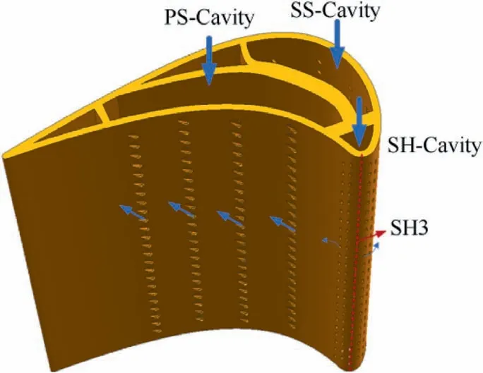
Fig. 2 Turbine blade and coolant distribution.
There are two blade models in this experimental study. Fig. 2 shows a schematic diagram of an improved blade model. All film cooling hole rows of the basic blade are cylindrical holes,and the blade model before and after improvement all have the same compound angle. Table 3 shows the Mass Flux Ratio(MFR) of the three sub-cavities under different working conditions. Regarding the determination of MFR, the method adopted is to measure the pressure distribution on the surface of the blade through static pressure measurement.As shown in Fig.3.,some of the static pressure measuring points are at the same position as the film holes. By measuring the static pressure of each measuring point, as well as the total pressure and static pressure of the mainstream,the local velocity at that point at the position of the film holes can be calculated on the blade,and the mass flow rate of each rows of film holes can be obtained through the area of the film hole and the flow density.The superposition of the flow rates of the film holes can obtain the mass flow rates of each cavity. In addition, the incoming flow velocity can be obtained by the difference between the total pressure and the static pressure of the mainstream, and the mass flow rate of the mainstream can be obtained through the area of the channel,so that the Mass Flux Ratio(MFR)of each cavity can be obtained.This method can try to ensure the mass flux ratio of each row of holes.Therefore,the Mass Flux Ratio (MFR) is defined as MFR = ˙m/ ˙m(where, ˙mis the flow rate of mainstream, ˙mthe flow rate of coolant).The basic blade is flattened, as shown in Fig. 4(a), and the improved blade is flattened, as shown in Fig. 4(b). The improved blade changes the cylindrical holes of the suction surface and pressure surface into the laid-back fan-shaped film cooling holes(hole 11–11–11, as shown in Fig. 5). Where, α is the injection angel of the hole, β is the lateral expansion angel of the hole,γ is the compound angel of the hole,δ is the streamwise expansion angel of the hole,θ is the thickness of blade wall,Lis the length of the cylindrical section,L is the length of the film cooling hole. The five rows of cylindrical holes at the leading edge remain unchanged. After the film cooling holes on the suction and pressure surfaces are improved,the injection angle and the compound angle of the hole are not changed,and the diameter of the cylindrical section of the laid-back fan-shaped hole is also the same as the original. Table 2 shows the detailed parameters of each row of film cooling holes on the blade.
In the experiment,the Reynolds number based on the blade chord length is guaranteed to be 1.7×10,and the mainstream speed is 20 m/s. The mainstream turbulence intensity is 16.00%when placing a turbulence generator in the flow channel, and this turbulence intensity is chosen based on the real condition behind combustor. There are two blade models in the experiment, and both models have three intake cavities,which control the secondary flow of the pressure surface(PS1, PS2, PS3, PS4), the suction surface (SS1, SS2, SS3,SS4), and the leading edge showerhead (SH1, SH2, SH3,SH4, SH5). The mass flux ratio distribution of the three cavities is shown in Table 3,and the density ratio is 1.0. The mass flux ratios are determined based on the actual conditions, and there also have several comparison cases near the actual conditions, the test conditions of this experiment are shown in Table 4.
2.4. Experimental method
PSP was originally used for noncontact pressure measurements.Photoluminescence and oxygen quenching are the main physical principles of PSP.After being illuminated by an excitation light source,the intensity of the light-emitting molecules in the PSP is inversely proportional to the partial pressure of oxygen around the PSP coating.At the same time,the oxygen molecules will also capture the energy of the light-emitting molecules, causing the light-emitting molecules to return to the ground state and no longer emit light.

Table 1 Blade geometric parameters.
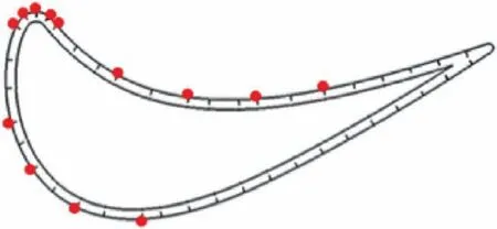
Fig. 3 Static pressure measuring positions and film hole row positions.
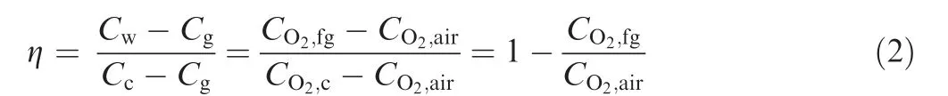
The adiabatic film cooling effectiveness can be summed up based on the PSP heat/mass transfer analogy,and the mathematical expression is as follows:

where T, Tand Tare the mainstream temperature, secondary flow temperature, and adiabatic wall temperature,respectively; Crepresents the gas concentration near the wall surface when the main flow and the secondary flow are mixed;Cstands for the mainstream gas concentration;and Crepresents the secondary gas concentration. Nitrogen was used as the secondary flow in this experiment, and the mainstream was still air.The oxygen concentration Cin the mainstream gas is the oxygen concentration Cin the air, and the oxygen concentration in the secondary flow is C,both of which are constant values.The oxygen concentration in the main and secondary flow blending gas is C,so Eq.(1)can be written as follows:
The relative molecular mass of nitrogen and air is approximately equal,and the mass fraction ratio of oxygen is equal to its partial pressure ratio, so the rightmost item of the Eq. (2)can be written as follows:

where Pis the partial pressure of oxygen in the air and Pis the partial pressure of oxygen in the air-nitrogen mixture.
The Pressure-Sensitive Paint used in this experiment is Uni-FIB;its excitation wavelength is 380–520 nm,and its emission wavelength is 620–750 nm. The calibration of the PSP before the experiment determines the relationship between the fluorescence intensity of the PSP and the partial pressure of oxygen. In the calibration experiment, a vacuum was extracted from the closed volume, the copper plate sprayed with PSP on the surface was placed in a closed container and could be heated by an electric heater. Two thermocouples were arranged on the surface of the copper plate to monitor the experimental temperature.During calibration,the temperature of the PSP on the surface of the copper plate is controlled by a heating module, and the pressure in the enclosed volume is controlled by a vacuum pump to change within the range of 10–100 kPa. By processing the pictures taken at different temperatures and pressures, the corresponding relationship between the fluorescence intensity value and the oxygen partial pressure at different temperatures can be obtained. The calibration results for the PSP at four different temperatures are given in Fig.6.Where,Iis the light intensity in standard condition, I is the light intensity in experimental condition, Pis the static pressure in standard condition, P is the static pressure in experimental condition. The polynomial fitting of the data points obtained by calibration can obtain the corresponding functional relations.
2.5. Uncertainty analysis
Hanand Natsuiet al. have performed much work on the uncertainty of PSP. According to their uncertainty analysis method, the resolution of PSP is the main factor causing the uncertainty of the experiment, and when the measured cooling effectiveness increases, the uncertainty of the PSP experiment will decrease. So, based on their method and current experiment conditions, the relative uncertainty of the film cooling effectiveness is no more than 5% in the current work.
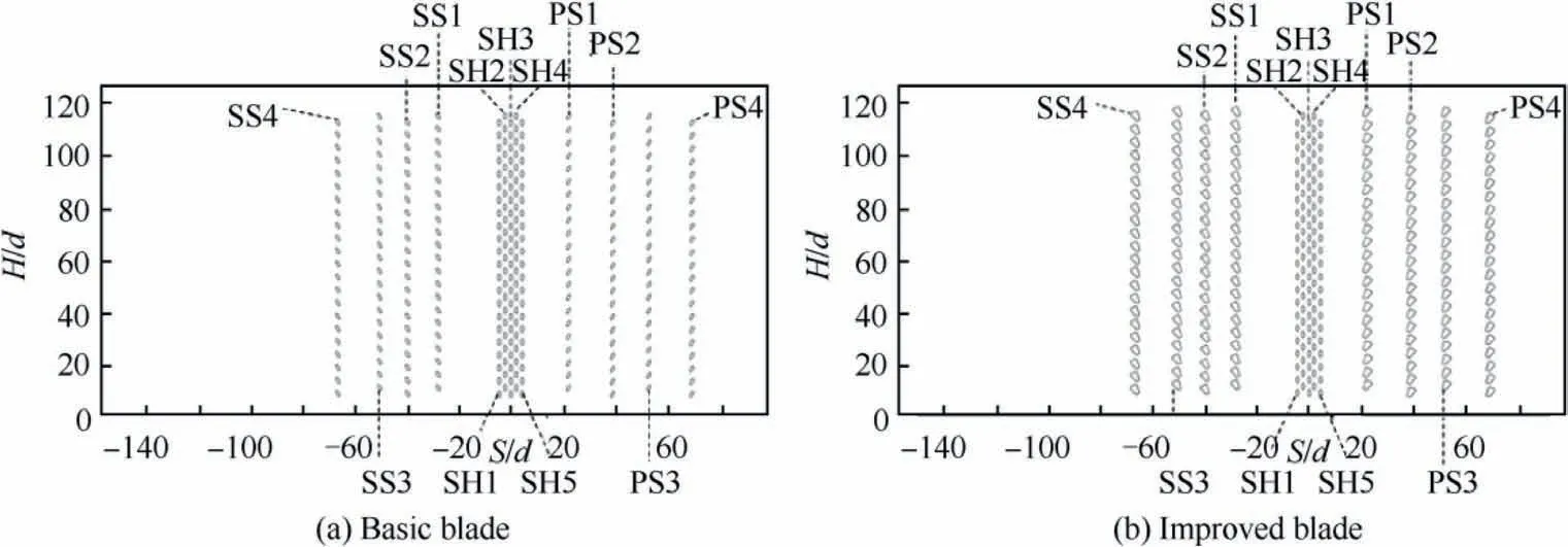
Fig. 4 Unfolded picture of the film hole positions on the blade surface.

Fig. 5 Configurations of laid-back fan-shaped hole.
3. Results and discussion
3.1. Film cooling effectiveness distribution – low turbulence intensity
The cylindrical hole row at the leading edge of the blade has the same incident direction(from the root to the tip of blade).Both the row of cylindrical holes and the shaped holes rows have a compound angle of 30° inclined to the blade tip.Fig.7 shows the film cooling effectiveness contours on the surface of the blades at a low turbulence intensity.Where,H is the blade height, S is blade arc length, d is the hole diameter. the Because the leading edge area is affected by the compound angle, the trajectory of the cooling jet is generally biased toward the blade tip. Under the drive of the mainstream, the cooling jet ejected from the leading edge spreads to both sides of the pressure surface and the suction surface.Near the blade root where the leading edge is in contact with the pressure surface, there are some film holes with almost no jet ejection.which is caused by the single-side coolant intake of secondary flow from the blade root.
As the mass flux rate increases, more coolant covers the leading-edge surface, and the film cooling effectiveness also increases. The larger the spanwise momentum of the coolant jet is, the more obvious the tendency of the film trajectory to deviate from the blade tip is. When the cylindrical hole is at the minimum total mass flux ratio (Case 1, MFR = 2.91%),the spreading momentum of the secondary-flow is small, and the film easily develops in the direction of the flow driven by the mainstream. The trajectory of the cooling jet is clearly visible in the area between SS1 and SH1,as well as between SH5 and PS1.The film coverage of the two regions near the root of the blade worsens with the mass flux ratio increases. On the one hand, the span momentum of the coolant is larger, and the jet trajectory is biased toward the blade tip; on the other hand, the normal momentum of the jet is larger, and the film is more likely to leave the leading edge surface.When the mass flux ratio is at a maximum(Case 4,MFR=11.63%),the cooling jet ejected from the leading edge film holes is close to the upper wall surface of the channel, and driven by the main-stream, it develops along the wall surface downstream.Because the improved blade model and the basic blade model in the leading edge area of the film cooling hole layout are completely consistent, the film covering effect is almost the same in the leading edge region (-8 < S/d < 8). It can be clearly seen from the figure that under the influence of the film jet from the downstream laid-back fan-shaped holes, the film coverage effect in the area between SS1 and SH1 and between SH5 and PS1 becomes significantly better.
Table 2 Geometric parameters of the laid-back fan-shaped hole
Affected by the passage vortex, the suction surface gradually converges along the flow coverage area. The jet trajectory of the downstream region of hole row SS1 is biased toward the tip of the blade. With an increase in the mass flux ratio, the jet’s deviation from the tip of the blade becomes more obvious.This change is affected by the compound angle of the filmholes.As the mass flux ratio becomes larger,the span momentum of the cooling jet shifting toward the blade tip becomes larger. The cylindrical holes of the suction surface have the best film coverage effect in Case 1.The area with the best film coverage appears near the SS4 row. On the one hand,the film cooling hole jets in the upstream SS1 and SS2 rows overlap in this area; on the other hand, the temperature of the mainstream near the boundary layer mixed with the SS4 and SS3 jets decreases after heat exchange with the SS2 and SS1 jets.As the mass flux ratio grows, the cylindrical holes of the suction surface gradually separated from the blade surface, and the film covering effect gradually worsens. However, due to the influence of coolant in the leading edge region, the film cooling effectiveness on the entire suction surface did not decrease monotonically.Affected by the upstream coolant outflow,at a large mass flux ratio,there is still a good continuous film coverage effect near the row of SS4.At the four mass flux ratios, the film coverage of the laid-back fan-shaped holes is much better than that of the cylindrical holes on the suction surface, which can form a continuous and good film covering effect. With an increase in the mass flux ratio, the cooling jet from the laid-back fan-shaped holes did not show obvious signs of detachment from the wall surface.It can be seen from the figure that the jet trajectory of the laid-back fan-shaped holes is shifted more toward the blade tip, because the expansion of the laid-back fan-shaped hole pattern along both sides makes the jet have a larger span momentum.
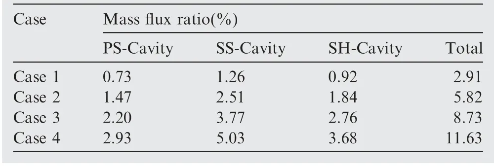
Table 3 Mass flux ratio distribution

Table 4 Test conditions
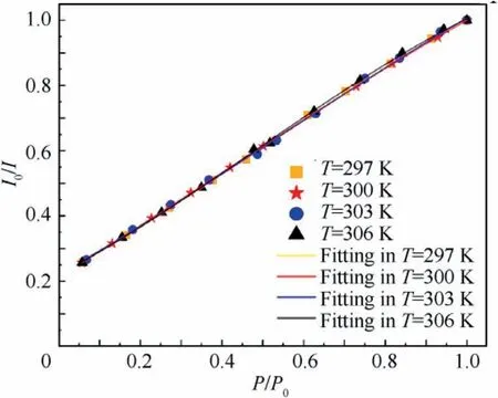
Fig.6 Calibration results for PSP at four different temperature.
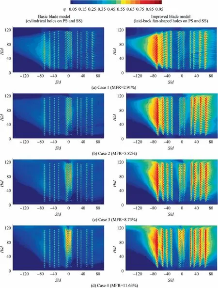
Fig. 7 Film cooling effectiveness contour maps (Tu = 0.62%).
The channel vortex on the pressure surface will disperse the film trajectory to both sides,but as seen from the figure,the jet trajectory of the pressure surface is inclined upward as a whole. This inclination is because the jet trajectory is more affected by the jet spanwise angle than by the channel vortex.Like the suction surface result,the cylindrical hole of the pressure surface has the best film coverage effect in Case 1.With an increase in the mass flux ratio, the effect of the film covering the pressure surface of the blade is more affected by the cooling jet of the upstream leading edge,and the cooling effectiveness does not decrease monotonically. When the cylindrical holes on the pressure surface are changed to the laid-back fan-shaped holes, the film coverage effect rises sharply. Especially at large mass flux ratios, the film covers the entire pressure surface very well. The area covered by the laid-back fanshaped hole rows on the pressure surface meets the high cooling effectiveness area affected by the leading edge.
Fig. 8 shows the laterally-averaged film cooling effectiveness with different mass flux ratios. As seen from the figure,on the suction surface side of the basic blade model, Case 1 has the best film cooling effectiveness and is far better than the other three cases. This result is due to the film coverage of the cylindrical holes on the suction surface becoming worse with an increase in the mass flux ratio, and the larger the mass flux rate of the leading edge is, the higher the cooling effectiveness of Case 3 and Case 4 is (compared with Case 2). The laterally averaged film cooling effectiveness on the pressure side exhibits a small change as the mass flux ratio increases. On the one hand, the film on the pressure surface will gradually separate from the wall surface as the mass flux ratio increases; on the other hand, the larger the mass flux ratio is, the greater the impact of the leading edge jet on the pressure surface is. Compared to the basic blade model,the laterally-averaged film cooling effectiveness on the suction surface of the improved blade model is less affected by the mass flux ratio. The cooling effectiveness on the pressure side is low at the three large mass flux ratios, but they are significantly higher than Case 1.
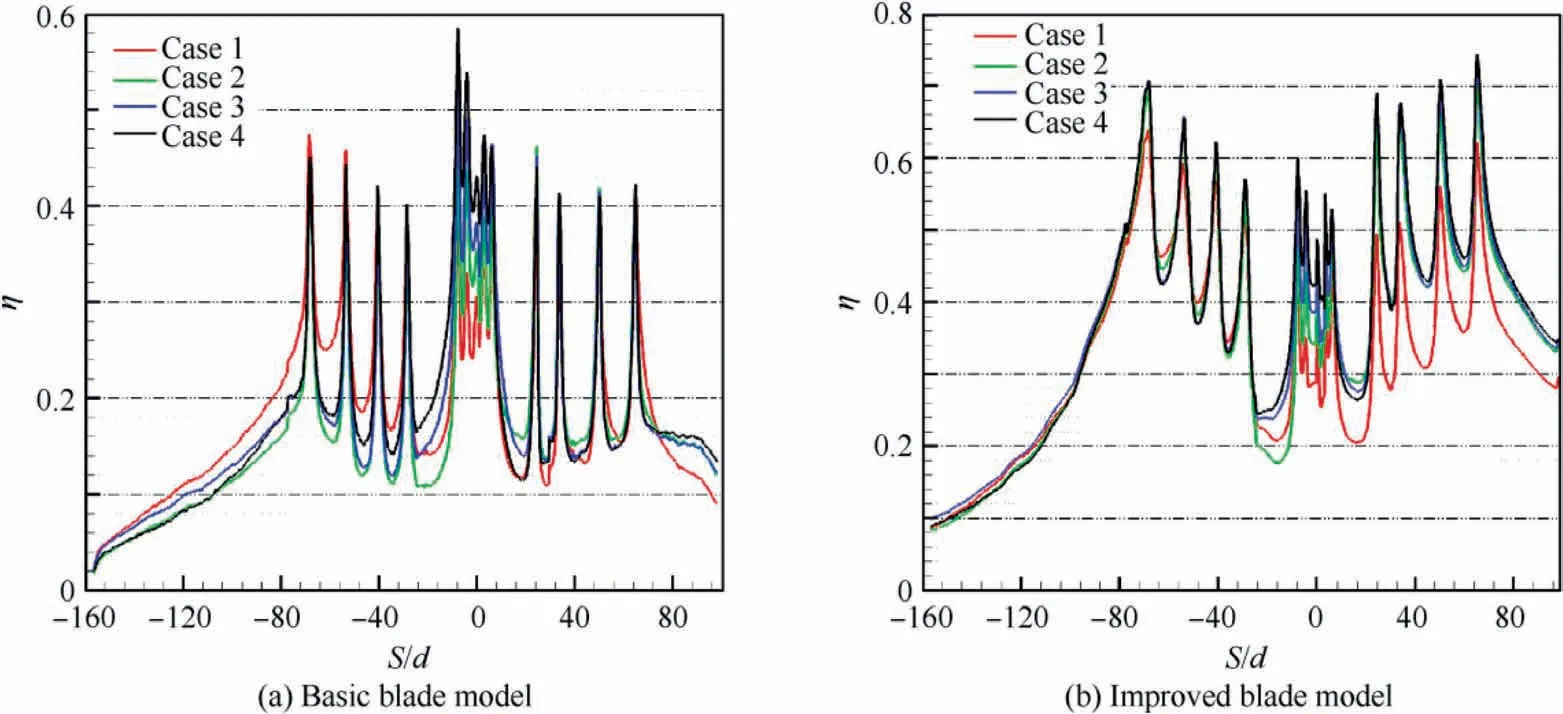
Fig. 8 Comparison of laterally-averaged film cooling effectiveness with different mass flux ratios (Tu = 0.62%).
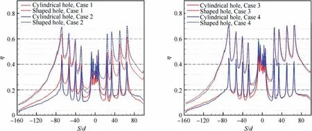
Fig. 9 Comparison of laterally-averaged film cooling effectiveness of different hole shapes (Tu = 0.62%).
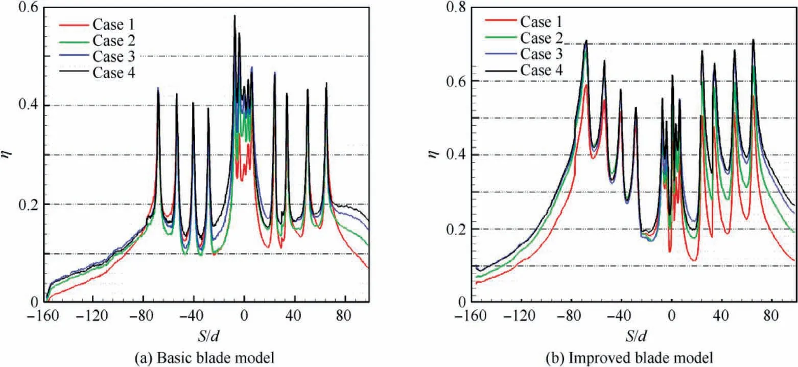
Fig. 10 Comparison of laterally-averaged film cooling effectiveness with different mass flux ratios (Tu = 16.00%).
Fig. 9 shows whether it is the suction surface or pressure surface, the laid-back fan-shaped hole greatly improves the film cooling effectiveness. On the pressure side and suction side, the increase in laterally-averaged film cooling effectiveness was more than 80% and 120%, respectively.
3.2. Film cooling effectiveness distribution – high turbulence intensity
Fig.10 shows the effect of the mass flux ratio on the laterallyaveraged film cooling effectiveness at high turbulence intensity.The experiment results show that the laterally averaged film cooling effectiveness of the two blade models increases with increasing mass flux ratio.Compared with the suction surface,the pressure surface is more affected by the mass flux ratio,especially in the downstream area with S/d > 60.
Fig.11 shows the film cooling effectiveness contour maps at a high turbulence intensity with different mass flux ratios. As with low turbulence intensity, dense cylindrical holes make the film coverage of the leading edge area very good. As the mass flux ratio increases,more coolant protect the leading edge surface, and the area with high cooling effectiveness becomes increasingly larger.The hole shape change on the downstream suction pressure surfaces has little effect on the leading edge,especially on the leading edge center area (the area near S/d = 0). Like the conclusion at low turbulence intensity, the improvement in the hole shape greatly enhanced the film cooling effectiveness on the suction and pressure surfaces.
The cooling effectiveness of the laid-back fan-shaped hole at each mass flux ratio is much higher than that of the cylindrical hole in Fig. 12. However, compared with low turbulence intensity(Tu = 0.62%), the advantage of the laid-back fanshaped hole is smaller than that of the cylindrical hole, and it is more obvious on the pressure side under high turbulence intensity(Tu = 16.0%) conditions.
3.3. The effect of turbulence intensity
It can be concluded that the increase in turbulence intensity significantly reduces the coverage distance in the coolant flow direction from Fig. 13. Affected by an increase in the turbulence intensity, the film coverage effect on the pressure surface and the suction surface near the leading edge worsens. After the turbulence intensity increases, the film covering effect of the cylindrical hole on the suction surface worsens, while the pressure side is different with different mass flux ratios. The turbulence intensity at low mass flux ratios will worsen the effect of the film coverage due to the intensified mixing of the mainstream and secondary flows. At large mass flux ratios, an increase in the turbulence intensity enhances the adherence of the film jet and improves the film coverage.
Fig. 13 shows the effect of the turbulence intensity on the film cooling effectiveness under the same mass flux ratio. It can be seen from the figure that at the four mass flux ratios,an increase in the turbulence intensity will reduce the film cooling effectiveness on the entire surface of the improved blade model. On the suction side of the basic blade model, an increase in the turbulence intensity will reduce the cooling effectiveness, while on the pressure side, this happens only at a low mass flux ratio. At large mass flux ratios, the cooling effectiveness of cylindrical holes will increase with increasing turbulence intensity, and the effect of the turbulence intensity on the cooling effectiveness weakens.the laid-back fan-shaped hole is more affected by turbulence intensity compared with the cylindrical hole, which is more obvious at small mass flux ratios(Case 1 and Case 2).Compared with the influence of turbulence intensity, the improvement in the hole shape has a greater effect on the film cooling effectiveness.

Fig. 11 Film cooling effectiveness contour maps (Tu = 16.00%).
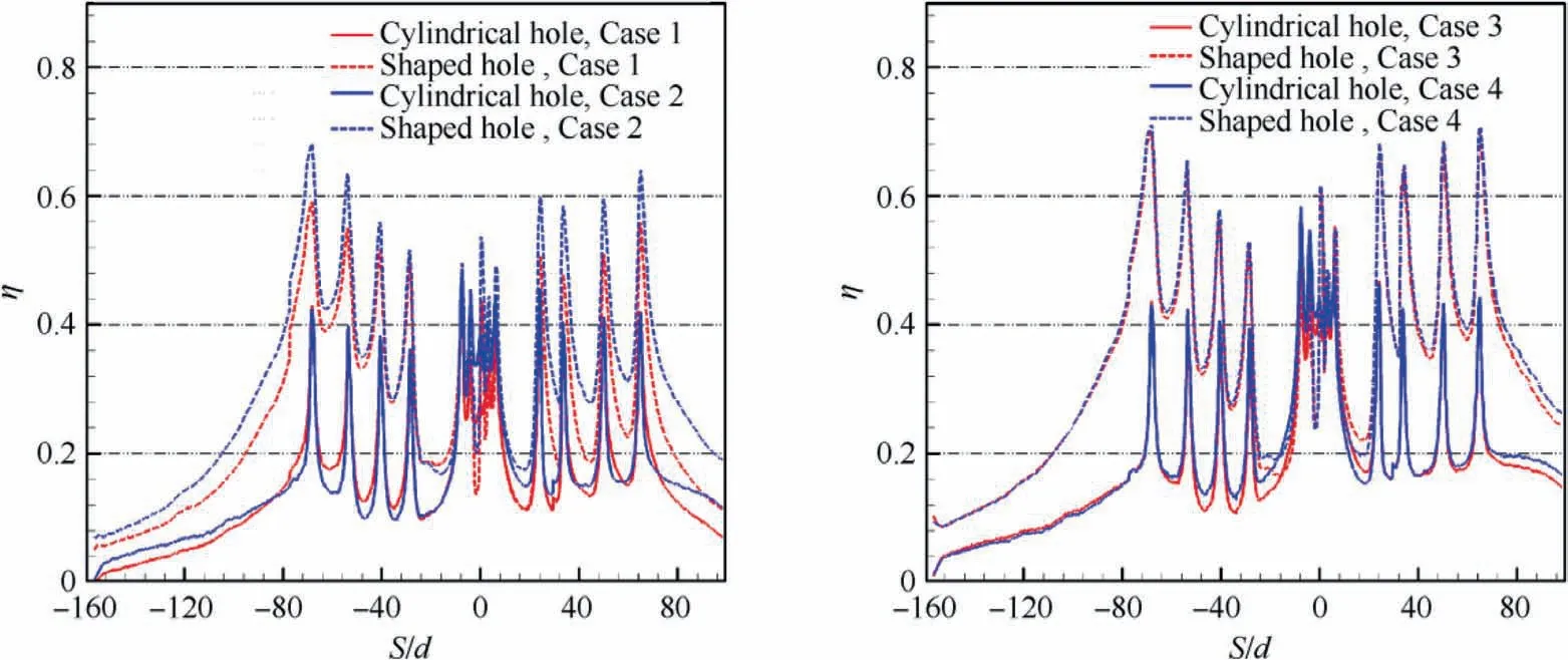
Fig. 12 Comparison of laterally-averaged film cooling effectiveness of different hole shapes (Tu = 16.00%).
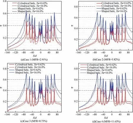
Fig. 13 Effect of turbulence intensity in different cases with both blade models.
4. Conclusions
The full-coverage film cooling characteristics of turbine blades were studied using PSP measurement technology, and the effect of the turbulence intensity and mass flux ratio on the surface film cooling effectiveness of turbine blades was studied in detail. The cylindrical holes on the suction and pressure surfaces of the blades were improved into laid-back fan-shaped holes, and experiments were performed to compare with the basic blade model. In summary, the experiment reached the following three conclusions:
(1) Dense rows of cylindrical holes are arranged in the leading edge area of the turbine blades, so that the leading edge area can form a continuous and good film coverage.Affected by the channel vortex in the cascade channel,the trajectory of the coolant jet on the suction face is convergent,while the trajectory of the coolant jet on the pressure face is divergent. Due to the influence of the leading edge hedge structure, the high cooling effectiveness area of turbine blades is mainly concentrated in the upper part of the midsection.
(2) The experimental results of blades show that the film covering effect of the laid-back fan-shaped holes with compound angle is much better on both sides of the pressure and suction surfaces than cylindrical holes with the same compound angle. The laid-back fan-shaped hole rows improve the cooling effectiveness of the suction side by 60% to 100% and 50% to 120% on the pressure side.
(3) An increase in turbulence intensity will reduce the cooling effectiveness of the blade surface.With an increase in the mass flux ratio,the influence of the turbulence intensity weakens. The experimental results of blades show that compared with multirow cylindrical holes,the cooling effectiveness of the film of the laid-back fan-shaped hole rows is more affected by turbulence intensity at small mass flux ratios.
The authors declare that they have no known competing financial interests or personal relationships that could have appeared to influence the work reported in this paper.
This Project was supported by the National Natural Science Foundation of China (No. 51936008), the Shaanxi Science Foundation for Distinguished Young Scholars (No. 2021JC-11), the National Science and Technology Major Project(No. 2017-III-0003-0027) and Innovation Foundation for Doctor Dissertation of Northwestern Polytechnical University(CX2021074).