Optimization and improvement of ac resistance calculation method for multi-phase parallel-wiring cables
Yoji ZHANG, Li WANG,*, Lexun MENG
a Department of Electrical Engineering, Nanjing University of Aeronautics and Astronautics, Nanjing 210016, China
b AC Systems, Power Grid Division, ABB, Stockholm 162 54, Sweden
KEYWORDS AC resistance;Main feeder;Orthogonal decomposition;Parallel-wiring strategy;Proximity effect
Abstract Parallel-wiring cables are often used in multi-phase AC aircraft Electrical Power Systems(EPSs).However,it complicates the ac resistance estimation.To solve this issue,an analytical resistance calculation method for parallel-wiring cables in multi-phase EPS was proposed. Firstly, the existing calculation formula of proximity factor was optimized, and the calculation error was reduced from 16% to 2% when two conductors are close to each other. Afterwards, the superposition effect on current density distribution between multi-conductors was considered based on orthogonal decomposition method, and the position of the equivalent charged points were easily determined. Finally, the ac resistance calculation formula was derived according to characteristics of parallel-wiring strategy, and the general ac resistance calculation methods of multi-phase parallel-wiring cables were presented.The proposed approach considerably enhances the applicability of ac resistance analytical calculation method for multi-conductor cables. Thanks to the accuracy of the proposed method, it can be used in many cases to avoid case-by-case simulation work and facilitate efficient system design and analysis.
1. Introduction
The high power rating Variable Frequency AC(VFAC)power supply system is featured in more/all electric aircraft.It has the advantages of simple structure, light weight, small volume,high energy conversion efficiency, high power density, high reliability and low cost.VFAC Electric Power System (EPS)has been applied in Boeing 787,A380 and other large civil airliners. However, the larger power supply capacity and wider power frequency range cause some critical issues, such as the variation of cable impedance characteristics, higher power loss, worse electromagnetic interference and so on, which increase design difficulty and risks.
In VFAC power system of aircraft, the main bus-bar is powered by the generator via three-phase main feeder. The characteristics of the main feeder have significant impact on the total weight,quality of power supply,and system reliability of the entire aircraft EPS. With the increase of power system capacity, the current rating and the main feeder length increase, and the parallel-wiring cables are more and more used. They certainly enhance the power transfer capability,but also introduce complexity in system design and analysis.In multi-phase EPS, the skin effect and the proximity effect are the major concerns due to tightly bundled cables for space saving purposes.The consequence of those effects includes potential higher power losses, uneven distribution of current/power in paralleled branches, as well as voltage unbalances between phases. The main power frequency range is widened to 360–800 Hz,as compared to the traditional 400 Hz constant frequency AC power system. The increase of frequency and main feeder length led to the larger main feeder impedance,bigger voltage drop and higher power loss.Furthermore,the parallel-wiring makes it more difficult to analytically estimate the resistance.
When the frequency of VFAC system changes from 360 Hz to 800 Hz, the ac resistance increases about 11%,18% and 30% due to skin effect for type AWG#0,AWG#2/0 and AWG#4/0 cables, respectively. The skin effect and proximity effect lead to uneven current distribution and increased ac resistance, which result in higher conductor loss and lower current carrying capacity. The exiting methods of reducing impedance are basically based on improving wiring strategy of cables.Some researchers pointed out that parallel-wiring cables can effectively reduce impedance. In 1963, Chen from Boeing Company studied the main feeders of Variable Speed Constant Frequency(VSCF) (4000–7800 r/min) power supply system of 20 kV∙A.He pointed out that the main feeder impedance was reduced by two bundles of cable in parallel wiring. In 1966, Howard from North American Airlines carried out impedance test for the main feeders of VSCF power supply system and concluded that twisted shielded wires have reduced zerosequence impedance, and parallel-wiring cable can effectively reduce overall impedance.NASA made a comprehensive summary for the development of various aircraft EPSs in 1960s, in which the cable impact on aircraft weight, transmission power capacity and other performance are emphasized.The report pointed out that the current carrying capacity per square area of the cable is related to the temperature, flight altitude, etc. The selection and design of cable, i.e. type, length, diameter, and wiring strategy, are carried out to guarantee that the voltage drop in all conditions are within certain limit. Refs. 11,12 found that the normal hexagon wiring strategy of single-phase in parallel could reduce the impedance, but quantitative impedance analysis has not been carried out.
At present,the calculation methods of skin factor and proximity factor include:(A)Simulation software is widely used to analyze such effects, but the Finite Element Method (FEM)can only simulate one kind of parameter combination for specified wiring strategy at a time. If the radius of conductors and the relative distance between conductors change,it is necessary to remodel and simulate. A lot of repetitive work need to be carried out,and it is highly time consuming and requires extensive computational resources.(B) The calculation method based on Bessel function can be used, but it is complex and practically difficult to be used in engineering design process.(C) The calculation method based on empirical formula has the disadvantage of unclear physical meaning.The correction coefficient, subjected to the change of conductor parameters, needs to be recalculated.
In 2014, Alan gave a new calculation method of skin factor and proximity factor.The proposed new formula is simpler and easier than the formula based on Bessel function. However, when the distance between two conductors decreases and reverse current flows through two conductors,the calculation error of proximity factor is larger. Ref. 20 derived an analytical ac resistance calculation method for multi-conductor feeder cables based on Payne formula,which has high precision. However, with the increase of power supply capacity, the parallel-wiring wires appears,the wiring structure of which is more complicated. Thus, it is necessary to investigate and derive a simpler and practical ac resistance estimation method.
In order to increase the applicable scope of ac resistance calculation method of multi-conductor cables with different wiring strategies, this paper develops an analytical calculation algorithm for parallel-wiring strategy. Taking threephase VFAC (360–800 Hz) power system of aircraft as example, the ac resistance of hexagon wiring of feeder cables is calculated to verify the accuracy of the proposed approach. The calculation process of the positive-sequence resistance and zero-sequence resistance are deduced, which are applicable to both three-phase symmetric system and unsymmetrical system. The tedious finite element simulation calculation is replaced.
2. Analysis of problem
With the increase of power system capacity,the current rating and the main feeder length increase, and the parallel-wiring cables are more and more used. The influence of skin effect and proximity effect are certainly decreased, and the ac resistance of conductors are also reduced. But the increase of conductor numbers makes the system design and analysis more complex. Taking usual triangle wiring strategy as an example,by dividing the current of each phase into two bundles of cable in parallel, the parallel-wiring wires are obtained, as shown in Fig. 1. By comparing two different wiring strategies, there are mainly the following differences: (A)Considering the problem of conductor volume and weight,the conductor becomes thinner under two bundles of cable in parallel condition, and the center distance between conductors decreases;(B)The number of conductors increases from 4 to 7.
The change of wiring strategy makes the deficiency of the existing ac resistance calculation method:
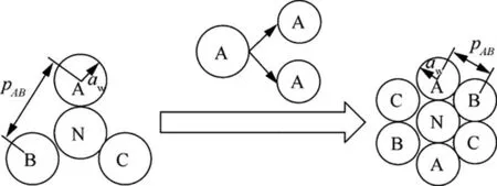
Fig. 1 Different wiring strategies.
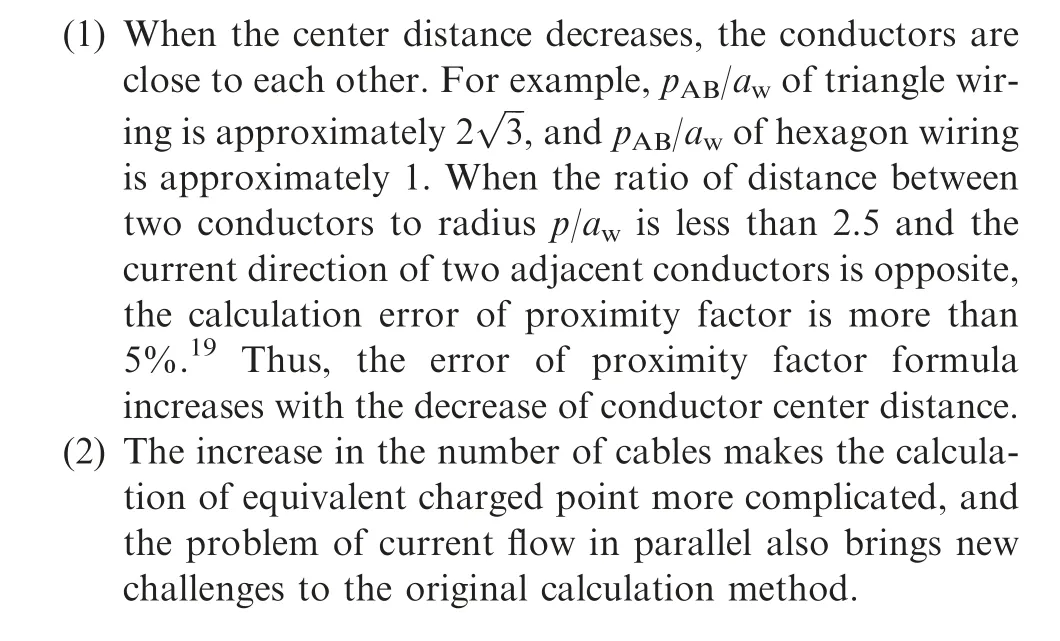
The two problems above are investigated, and the existing calculation methods are optimized and expanded.
3. Optimization of proximity factor calculation method
The two conductors are shown in Fig. 2.
The calculation formula of proximity factor between two conductors is given in Ref. 19 as
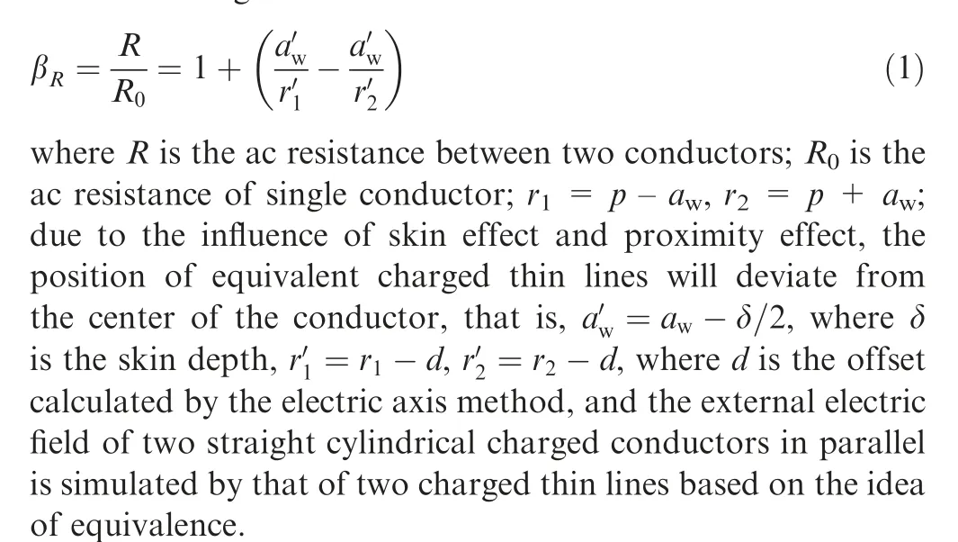
Taking AWG#4/0 cable with conductive radius of 5.842 mm as an example,the error between the calculation values in Eq.(1)and the simulation values of ANSOFT is shown in Fig. 3, where f is frequency.
As can be seen from Fig.3 that,when the distance between two conductors is smaller, the error value is larger. When two conductors are close together, e.g. p = 16 mm, the error can reach 16%. And the error is 6% when the conductor distance is 20 mm.A much higher accuracy can be achieved in the case that the distance between two conductors is larger than 25 mm.The maximum error at this time is about 5%,but it only exists at specific frequency, and in most of the frequency range, the error is lower than 2%.
Fig. 4 shows the magnetic induction intensity B between two conductors. It can be seen that the proximity effect has a great influence on distribution of magnetic lines, especially when the center distance of two conductors is close.
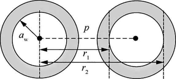
Fig. 2 Position of two conductors.
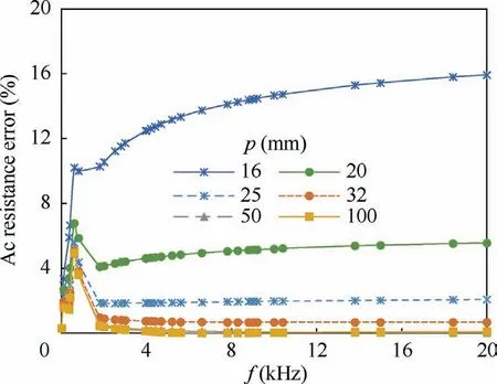
Fig. 3 Calculation error curves of ac resistance for two conductors (opposed current).
Obviously, Payne’s calculation method cannot accurately calculate ac resistance when two conductors are close to each other, in the case of which the conductive radius is smaller and conductor center distance is shorter, e.g. parallel-wiring cables. It is necessary to optimize the calculation formula of proximity factor as the first step.
Assuming that the current direction in two adjacent conductors(A&B conductors)is opposite in Fig.5,the proximity effect of A conductor on B conductor is analyzed. The alternating magnetic field Bwill be generated by A conductor with alternating current i, the alternating magnetic field passes through a cross section of B conductor, and eddy current iwill be generated, which is induced current in B conductor caused by proximity effect, as shown in Fig. 6, where J is current density. The induced current will generate induced magnetic field in B conductor, the magnetic field distortion caused by superposition of induced magnetic field and original magnetic field,which is more serious when the conductors distance is smaller. With the increase of conductor distance, the distortion decreases. This is consistent with the rule that the error decreases with the increase of conductor distance in Fig. 3.
Combined with Payne’s calculation method, this part of distortion is corrected and recalculated, the integral is done in a new interval, and the effect of distortion is therefore considered. The proximity factor formula is as

According to symmetry,the ac resistance of B conductor is equal to that of A conductor.
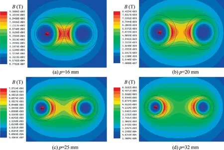
Fig. 4 Magnetic induction intensity distribution maps.
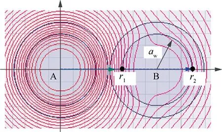
Fig. 5 Magnetic field line distribution map (p = 16 mm).
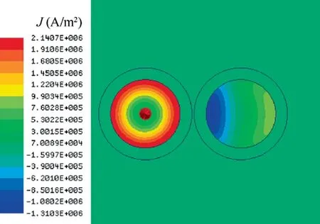
Fig. 6 Current density distribution map (p = 16 mm).
The ac resistance values calculated with Eq. (3) are compared with the simulation values obtained using ANSOFT software,and the error is shown in Table 1.AWG#4/0 cable with conductive radius of 5.842 mm is used for comparison.As can be seen in Table 1,most of the error values are within 3%in the frequency range above 2.00 kHz. However, the error is larger in the low frequency range with maximum error of 5%at the specific frequency point. When the center distance is greater than 20 mm and the frequency range is above 2.00 kHz,with the increase of center distance between two conductors,the calculation errors decrease,and the error tends to stabilize with the increase of frequency.
So the optimized calculation formula can improve calculation accuracy.Based on the optimized calculation formula,the analytical calculation method of ac resistance for parallelwiring strategy is deduced.
4. Calculation method of ac resistance for multi-phase parallelwiring strategy
In 230 V AC, 360–800 Hz, 250 kV∙A aircraft EPS, the main generator supplies AC power.Due to the imperfection of components/equipment, the three phase voltages/currents are not accurately balanced. The existence of single-phase load also incurs higher level of voltage/current imbalances between phases, namely unsymmetrical system, whose three phase quantities can be decomposed to three balanced systems,namely positive, negative and zero sequence systems, in order to simplify the analysis.The ac resistance of three-phase unsymmetrical system consists of the positive-sequence resistance, negative-sequence resistance and zero-sequence resistance. The calculation process of negative-sequence resistance is the same as that of positive-sequence resistance, but that of zero-sequence resistance is different.
Next, the positive-sequence resistance and zero-sequence resistance of parallel-wiring strategy are calculated respectively.
The typical hexagon parallel-wiring strategy is taken as an example, as shown in Fig. 7. There are two cables for each phase. A neutral wire also exists along with the three-phase wires.The parallel-wiring can reduce skin effect and proximity effect, and thus the ac resistance is decreased.
4.1. Positive-sequence resistance
The positive-sequence resistance is the ratio of positivesequence voltage to positive-sequence current. The positivesequence currents are first segmented according to the direction (positive/negative sign) of the current, as shown in Table 2.

Table 1 Ac resistance error of two conductors.
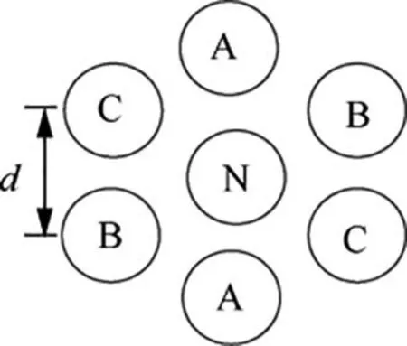
Fig. 7 Hexagon wiring strategy.
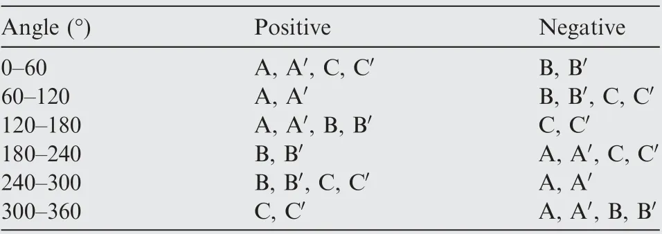
Table 2 Segment of three-phase current.
The hexagon parallel-wiring strategy has a complex structure, the orthogonal decomposition is used to superpose the influence between adjacent conductors considering the large number of conductors and mutual impact. Firstly, the offset between two conductors can be calculated by using the electric axis method and uniqueness theorem,which can be represented by a vector with direction, as shown in Fig. 8. Thus,the mutual impact of proximity effects among all conductors are regarded as the result of superposition and cancellation of vectors in different directions.
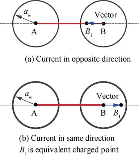
Fig. 8 Position for equivalent charged point and vector.
The orthogonal decomposition method, which decomposes a vector in two selected perpendicular directions to solve vector operation with algebraic manipulation, is used to simplify the process of vector superposition, and the position of equivalent charged point is obtained.
Taking the 0°–60° range as an example, the directions of Phase-A current, Phase-Acurrent, Phase-C current and Phase-Ccurrent are positive. The directions of Phase-B current and Phase-Bcurrent are negative. The directions of Phase-A current and Phase-B current are opposite, and the position of the equivalent charged point is on the center line of AB, where the proximity effect from Phase-B tends to shift the charged thin line of Phase-A to a new point near Phase-B.The offset is represented by q, as shown in Fig. 9. Similarly,the effect from Phase-C tends to shift the charged thin line of Phase-A to a new point which is away from Phase-C, and the offset is represented by q. In the same way, the offset of Phase-B, Phase-Cand Phase-Aare respectively obtained,and the offsets are represented by q, qand q. The details are shown in Fig. 10.
The superposition of the proximity effect from Phase-B,Phase-B, Phase-C, Phase-C, and Phase-Aresults in the estimated final position Aby orthogonal decomposition method,and the green thin line in Fig.10 represents the equivalent center distance associated with A.
According to the orthogonal decomposition method:

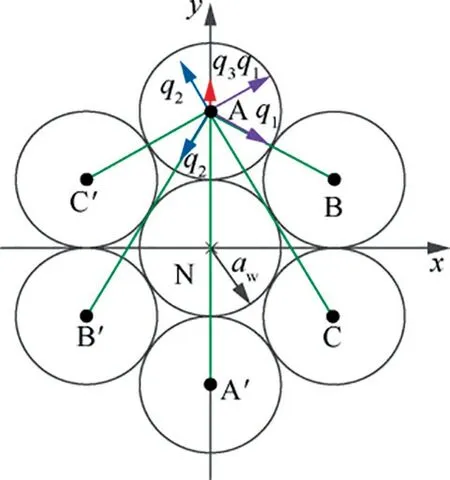
Fig. 9 Position for equivalent charged thin line of Phase-A(hexagon wiring strategy, positive-sequence resistance).
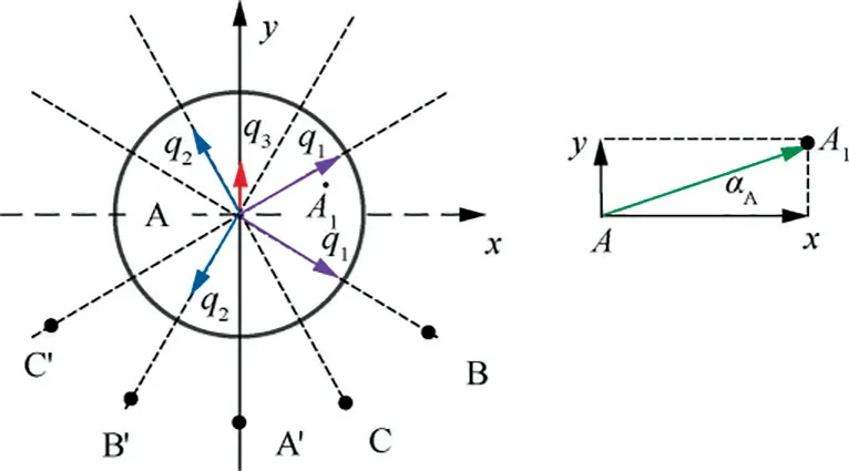
Fig. 10 Orthogonal decomposition details for equivalent charged thin line of Phase-A.
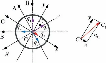
Fig. 12 Orthogonal decomposition details for equivalent charged thin line of Phase-C.
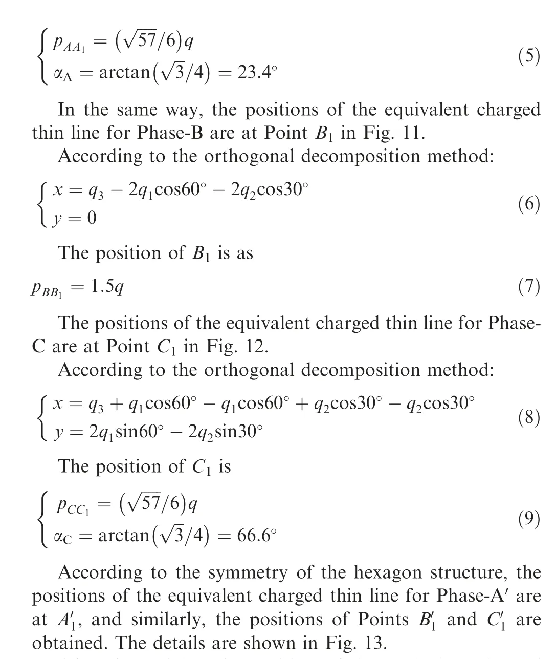
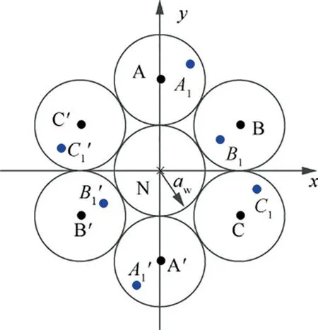
Fig. 13 Position for equivalent charged point.
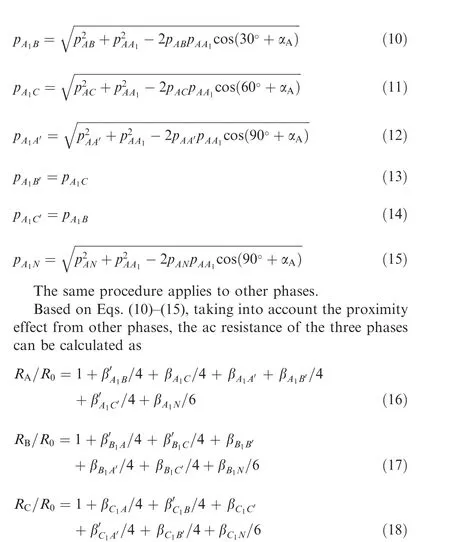
After determining the position of the equivalent charged thin line, the equivalent center distance between them can be calculated. The hexagon parallel-wiring strategy consists of 7 conductors, and 6 equivalent center distances are related to Phase-A, such as p, p, pand so on. According to the geometrical fundamentals, the equivalent center distances are respectively
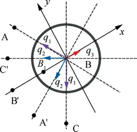
Fig. 11 Orthogonal decomposition details for equivalent charged thin line of Phase-B.
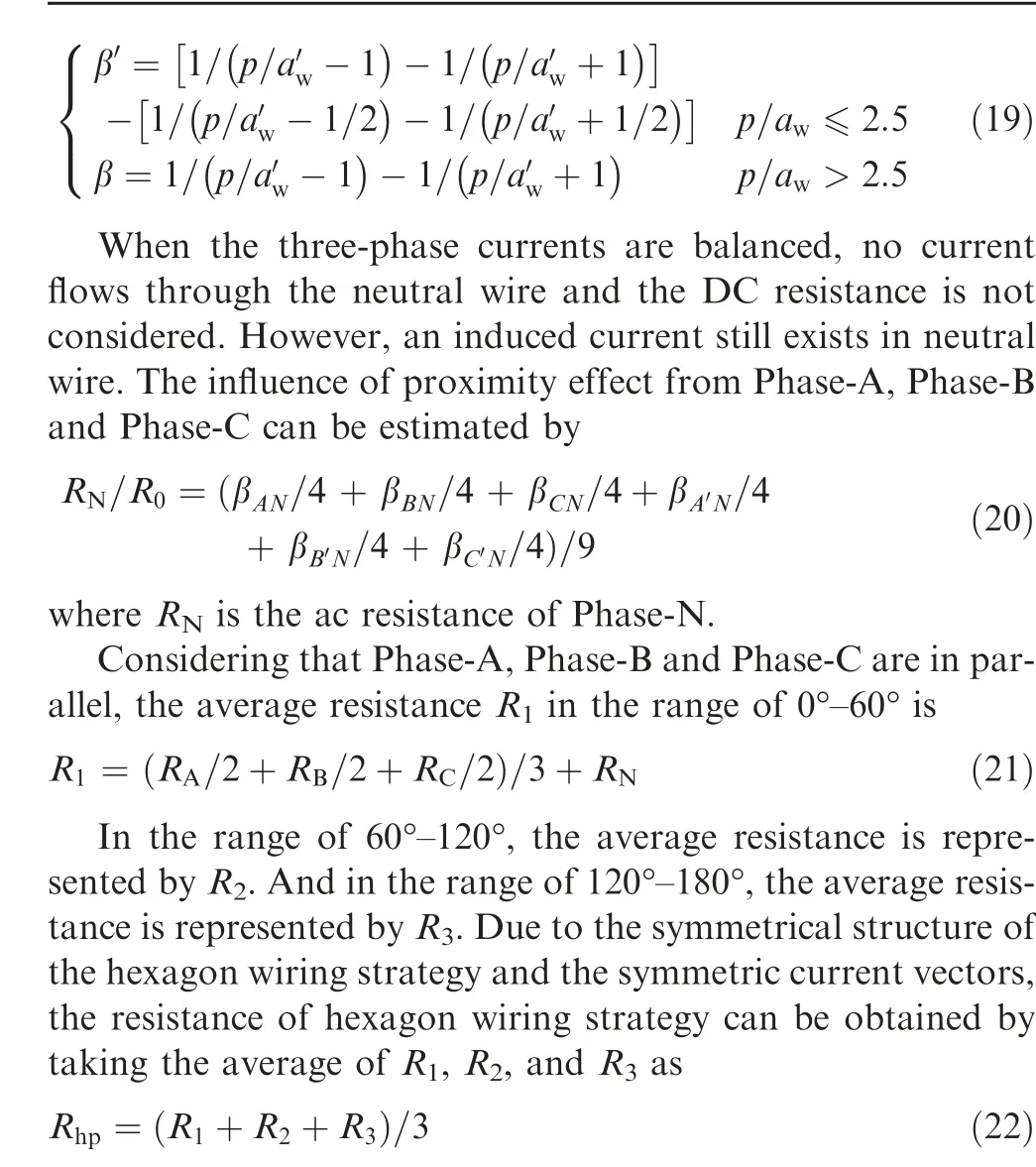
where R,Rand Rare the ac resistance of Phase-A,Phase-B and Phase-C, respectively;β and βwith different subscripts are the proximity factors,which can be calculated according to the center distances.
The ac resistance values calculated with Eq. (22) are compared with the simulation values obtained using ANSOFT software. As can be seen in Fig. 14, most of the error values are within 2% and the maximum error of about 6% at 0.80 kHz. The larger error of low frequencies is caused by the calculation error of skin factor formula,which is piecewise function form related to frequency.
Obviously,the positive-sequence resistance of hexagon wiring strategy is calculated well using the method.
4.2. Zero-sequence resistance
The difference between the zero-sequence current and the positive-sequence current is that there are three times of reverse current flowing through the neutral conductor, so the influence of Phase-N on proximity effect should be considered.The positions of the equivalent charged point are shown in Fig. 15.
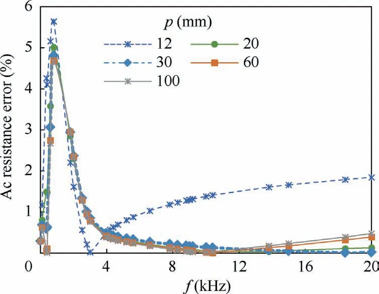
Fig. 14 Ac resistance error curves of hexagon wiring strategy.
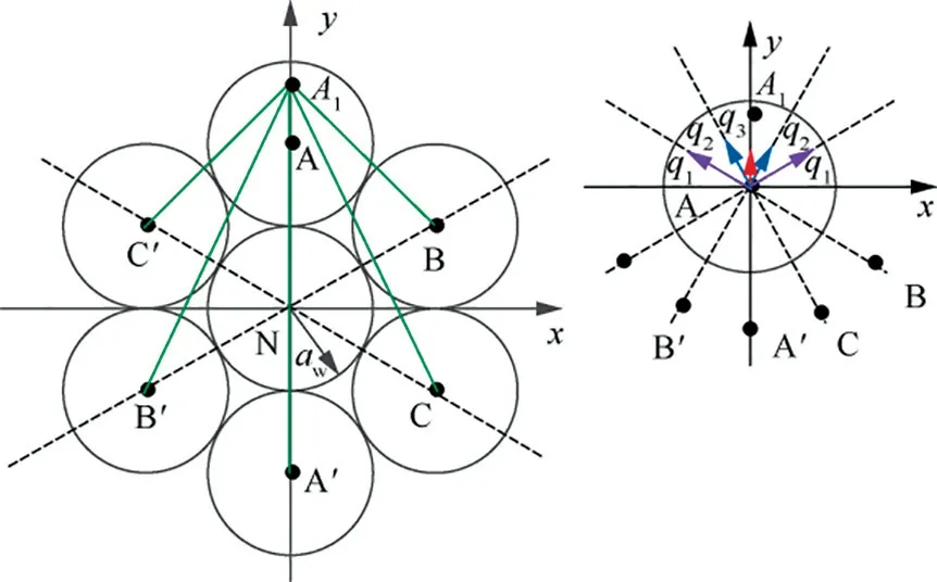
Fig. 15 Position for equivalent charged thin line of Phase-A(hexagon wiring strategy, zero-sequence resistance).
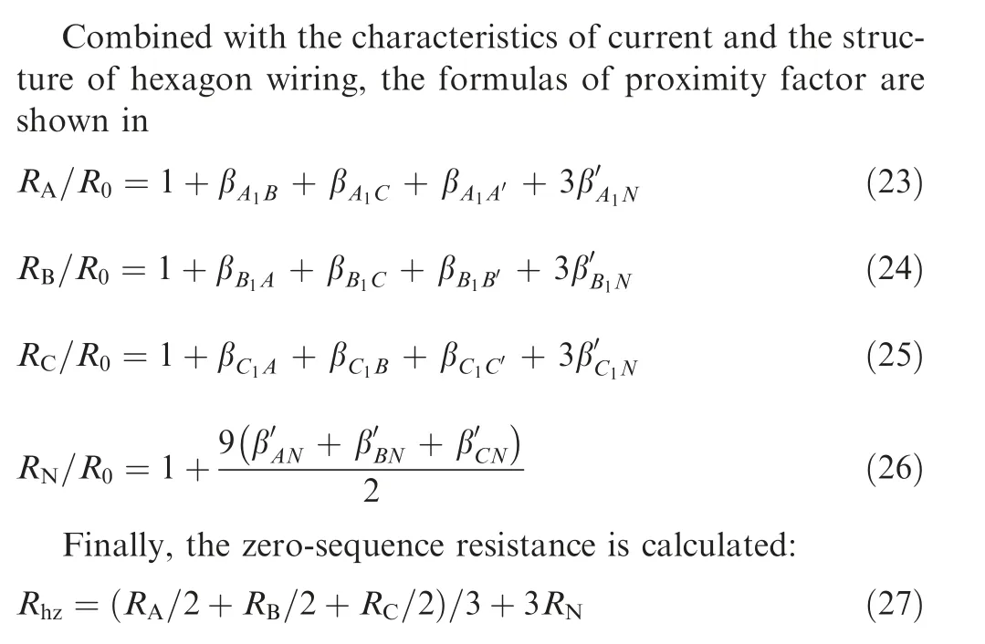
The ac resistance values calculated with Eq. (27) are compared with the simulation values obtained using ANSOFT software. The error is shown in Table 3 and the error curves are shown in Fig. 16. The calculation error of zero-sequence resistance for hexagon wiring strategy is slightly larger than that of positive-sequence resistance. The error tends to stabilize with the increase of frequency. When the centre distance is greater than 20 mm and the frequency range is above 2.00 kHz, with the increase of center distance between conductors,the error decreases, and the maximum error is around 10%.
4.3. Summary of general calculation methods
The key steps of the proposed calculation method are summarized:
(1) The current in three-phase AC system is decomposed to symmetrical components. The currents are segmented according to the direction of current.
(2) Based on the orthogonal decomposition method, the influence of proximity effect is superposed. The vector superposition method is used to reflect the interaction influence between conductors and determine the position of equivalent charged point.
(3) According to the position of equivalent charged point,the equivalent center distance between two conductors is calculated by cosine theorem and uniqueness theorem.
(4) The general calculation formula of proximity factor is as follows(taking X conductor as an example,X means A,B, and C respectively)

Table 3 Zero-sequence resistance error of hexagon wiring strategy.
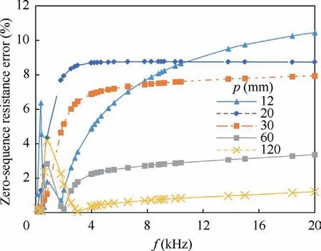
Fig.16 Zero-sequence resistance error curves of hexagon wiring strategy.
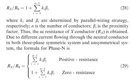
(5) According to the characteristics of parallel-wiring strategy, the ac resistance of each phase is obtained.
The calculation method proposed is applicable to both three-phase symmetric system and unsymmetrical system.
5. Verification for ac resistance calculation method of multiphase parallel-wiring strategy
In order to verify the applicability of the proposed method, a paralleled wiring which has different wiring strategies and different conductor positions is tested. Each phase is constituted by two conductors. The Phase-A, Phase-B, Phase-C and Phase-N are arranged in parallel as shown in Fig. 17.
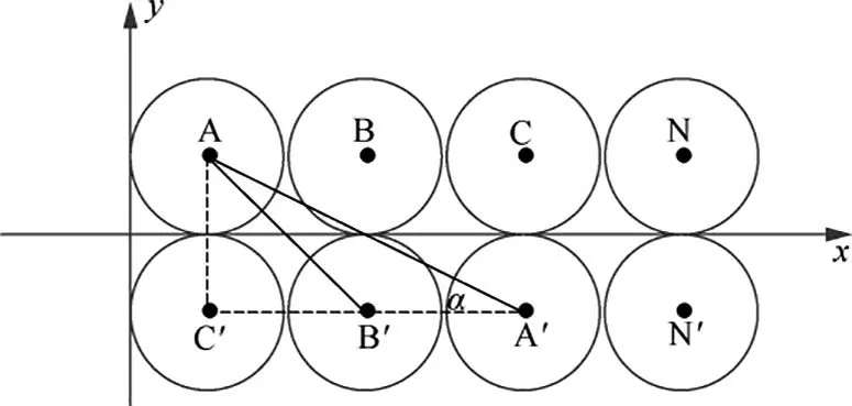
Fig. 17 Structure of paralleled wiring.
In order to distinguish the conductor, another group cable is called Phase-A,Phase-B,Phase-Cand Phase-N.By applying the method described in Section 3, the positive-sequence resistance and zero-sequence resistance are calculated respectively.
In order to unify the parallel wiring structure,the following assumptions are made. When the center distance changes, the conductor distance in the x-axis direction and the y-axis direction changes at the same time, that is, the distance of Phase-A and Phase-B is always equal to that of Phase-A and Phase-C.Thus,the Point Bis always in the direction of 45°with respect to Point A, and Point Ais always in the direction of α, where α = arctan 0.5.
When the positive-sequence resistance of paralleled wiring strategy is calculated, it is complex to determine the position of equivalent charged point due to the asymmetrical paralleled structure.The positions of equivalent charged point in the segment range 0°–60° are given as an example in Fig. 18. The angle between AAand the x-axis is γ.
Afterwards, the equivalent center distance between two conductors is obtained. And the calculation formula of proximity factor for paralleled wiring strategy is
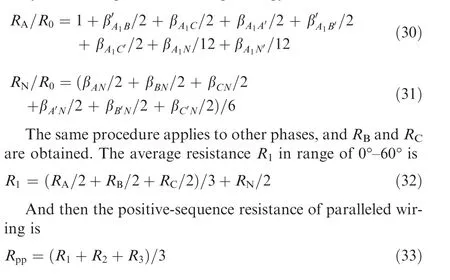
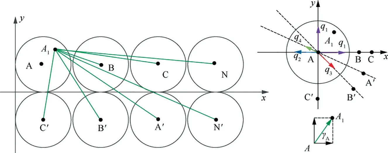
Fig. 18 Position for equivalent charged thin line of Phase-A (paralleled wiring strategy, positive-sequence resistance).
When the zero-sequence resistance of paralleled wiring strategy is calculated,the positions of equivalent charged point are shown in Fig. 19.
The calculation formula of proximity factor is
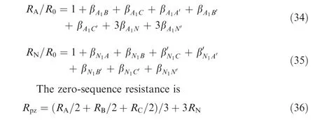
The ac resistance values calculated with Eqs. (33) and (36)are compared with the simulation values obtained using ANSOFT software. The error of positive-sequence resistance and zero-sequence resistance for paralleled wiring are shown in Table 4. For positive-sequence resistance, when the frequency range is above 0.8 kHz, the error decreases with the increase of frequency, and maximum error is around 6% at 0.80 kHz. For zero-sequence resistance, most of the error values are within 10%. However, when the center distance is greater than 20 mm, with the center distance decreases, the error increases, and the maximum error is about 11%.
In conclusion,the analytical calculation method of ac resistance of parallel-wiring strategy proposed has the following characteristics:
(1) The existing calculation formula of proximity factor is optimized when two conductors are close to each other,and the calculation error is reduced from 16% to 2%.
(2) Multi-phase parallel-wiring has complex structure and characteristics. Based on the orthogonal decomposition method, the influence of proximity effect between wires/phases is superposed. The mutual impact of multi-conductor is fully considered. The solution process of equivalent charged points is simplified.
(3) The proposed approach is applied to the calculation of positive-sequence resistance, negative-sequence resistance and zero-sequence resistance simultaneously, and is also applicable in both three-phase symmetric system and unsymmetrical systems.
(4) The proposed approach has high accuracy for the calculation of positive-sequence resistance and negativesequence resistance.
(5) The calculation error of zero-sequence resistance in proposed approach is slightly larger than that of positive-sequence resistance, and the maximum error is about 11%. However, the unbalanced load power in the aircraft VFAC system does not exceed 1% of the total power, that is, the zero-sequence resistance only accounts for a small part of the total ac resistance.
(6) The ac resistance value per unit length for multiconductor are investigated, and the special structures such as corners and connecting terminals are not considered. For future study considerations, the authors will promote the method to the analysis of three-dimensional magnetic field effect and the ac resistance calculation of three-dimensional structure.
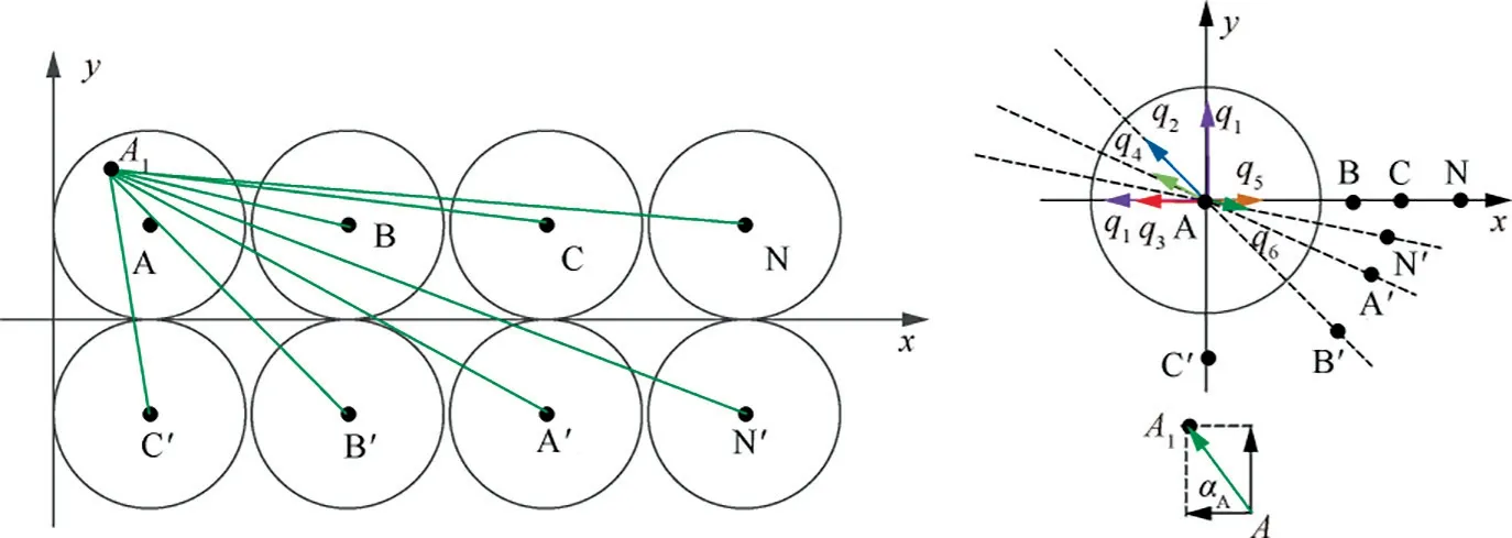
Fig. 19 Position for equivalent charged thin line of Phase-A (paralleled wiring strategy, zero-sequence resistance).

Table 4 Error of ac resistance for paralleled wiring.
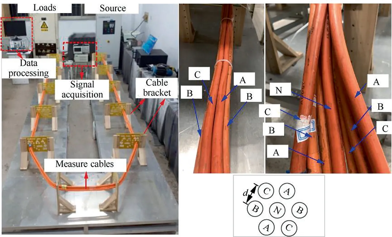
Fig. 20 Experimental platform and partial cable laying diagram.
6. Experimental verification
Based on the existing experimental platform, the ac resistance of hexagon wiring strategy is measured, and the effectiveness and accuracy of the proposed method are validated. The experimental platform is shown in Fig. 20. The length of test cables in the experiment are 9.2 m, with conductive area of 50 mmand center distance of 15 mm between two cables.The test current is 20 A/360–800 Hz, the voltage and current of test cables are collected by signal acquisition system.
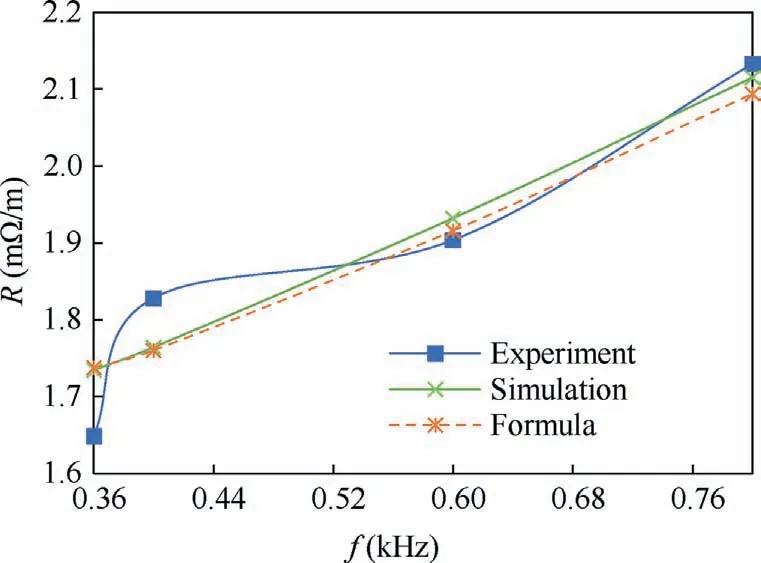
Fig. 21 Ac resistance under different conditions.
The ac resistance values and errors are respectively shown in Fig. 21 and Fig. 22. It can be seen that the error among experiment value,simulation value and formula value is small.It indicates that the analytical calculation method of ac resistance of parallel-wiring strategy proposed is accurate and effective.
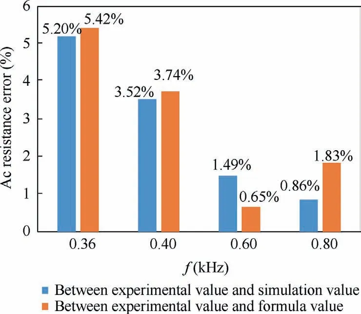
Fig. 22 Ac resistance error under different conditions.
7. Conclusions
This paper develops an analytical calculation algorithm for parallel-wiring strategy, which extends the application scope of ac resistance analytical calculation method for multiconductor wiring strategies. Some conclusions are drawn as follows:
(1) Under parallel-wiring strategy condition, the conductor radius becomes thinner, the center distance of conductors decreases, the existing calculation formula of proximity factor is optimized, which is more suitable for conductors close to each other,and the calculation error is reduced from 16% to 2%.
(2) The number of conductors increases from 4 to 7 or more, and the current of each phase is divided into two or more bundles of cable in parallel.It is more complicated to calculate the ac resistance of parallel-wiring strategy. The orthogonal decomposition method is used to simplify the calculation process of equivalent charged point, and the range covered with the ac resistance analytical calculation method is expanded.
(3) The general ac resistance calculation methods of multiphase parallel-wiring cables are presented, which are applicable to both three-phase symmetric system and unsymmetrical system. The error of positive-sequence resistance is less than 6%, and that of zero-sequence resistance is less than 11%.
The proposed method can replace the tedious finite element simulation process, and simplify the calculation process of ac resistance for multi-phase parallel-wiring cables.
In the further research work, the analysis of threedimensional magnetic field effect and the ac resistance calculation of three-dimensional structure will be further considered.Also,it is necessary to optimize the wiring strategy of main feeder for future investigation considerations,and the mathematical models of important parameters such as impedance,temperature rise, volume and weight need to be built successively. The mathematical model of ac resistance has been established,which is the basis for multi-objective optimization of main feeder wiring.
The authors declare that they have no known competing financial interests or personal relationships that could have appeared to influence the work reported in this paper.
This study was co-supported by the National Natural Science Foundation of China (No. 51877102) and the Innovation Foundation of Jiangsu Province, China(No.KYLX16_0365).
