Simultaneous optimization of structure together with attached tuned mass dampers considering dynamic performance
Lei SHEN,Xiaohong DING,Tiannan HU,Min XIONG,Heng ZHANG
School of Mechanical Engineering,University of Shanghai for Science and Technology,Shanghai 200093,China
KEYWORDS Dynamic performance;Harmonic excitation;Topology optimization;Tuned mass damper;Tuning optimization
Abstract Tuned Mass Dampers (TMDs) are often attached to a main structure to reduce vibration,and the TMDs’ positions are important to affect the structural dynamic performance.However,the TMDs’ positions and the material layout of the structure act on each other.This paper suggests a design optimization method by combining the topology optimization of the main structure and the layout of the attached TMDs under harmonic excitations.The main structure with the attached TMDs are modeled by the continuum FEA method to consider the change of TMDs’locations.Then they are optimized simultaneously by introducing a multi-level optimization frame,which includes the structural topology optimization and the optimal tuning of TMDs.The locations and damping parameters of TMDs are optimized in every step of the SIMP-based topology optimization of the main structure,so as to fully consider the interactions between each other to improve the dynamic performance.Numerical examples of cantilever structures are studied,and the results show that when the main structure and TMDs are optimized simultaneously,the modal strain energy is more concentrated compared with that obtained by the non-simultaneous optimization approach.Therefore,the dynamic compliance of the target mode is dramatically reduced.
1.Introduction
Vibration of aeronautics and machine structures during working process is harmful and inextricable.Considerable research efforts have been put into the design methods for vibration reduction purpose in recent years.Since the major source of vibration or noise in a structural system corresponds to harmonic force,it is of great importance to minimize the dynamic response subjected to harmonic excitations.In general,there are two approaches to reduce the vibration of structures,one is to design the structure with optimization techniques,and another is to adopt damping effects.
From the perspective of structural design,Topology Optimization (TO) is currently one of the most promising design methods,and can help designers to find the optimal material utilization to achieve given objective,and has been widely adopted in both academic research and applications in aerospace engineering,mechanical engineering and other manufacturing industries.TO techniques such as the Solid Isotropic Material with Penalization (SIMP),level set,and the Evolutionary Structural Optimization(ESO)have been developed in theoretical studies and practical applications.TO aiming for dynamic problems is mainly focused on two types of issues.One is related to eigenfrequencies,such as maximization of fundamental eigenfrequency,obtaining desired eigenfrequencies,high order eigenfrequencies and the gap between two consecutive eigenfrequencies of given orders.Another challenging issue is to minimize the dynamic response.For instance,He et al.formulated a density-based TO method to minimize the dynamic responses subjected to stationary random base acceleration excitations.Ma et al.used the homogenization technique to achieve the minimization of dynamic compliance under harmonic force excitations.Zhao et al.studied TO of large-scale structures with proportional damping subjected to harmonic excitations.Zhu et al.studied the structural TO methods related to dynamic responses under harmonic base acceleration excitations by combining large mass method and mode displacement method.
On the other hand,from the perspective of damping effects,one of the most useful approaches is to apply additional auxiliary damping systems such as Tuned Mass Dampers(TMDs),which is widely applied in engineering fields.A single TMD consists of a single mass absorber with special stiffness and damping,which has the feature of simplicity and low cost,and is compact with a low volume ratio.Through the optimal tuning of TMD parameters,the dynamic response at the resonance of the main structure can be decreased.The optimal tuning of TMD has been studied by analytical and numerical methods.For practical applications,Wan et al.proposes a new idea for designing a TMD to reduce vibrations in milling of cylindrical parts.Gao et al.summarized the applications of vibration absorber (TMD) for aircraft hydraulic pipeline system,and the vibration of target mode can be reduced effectively.Munoa et al.carried out a new damping module for workholding systems to reduce the machining chatter based on the concept of variable stiffness TMDs.Altintas et al.adopted multiple TMDs to increase chatter resistance of the machine tool structures.For civil engineering problems,Nigdeli et al.adopted novel metaheuristic algorithms for optimal tuning of TMDs to control the vibration of building structures.During the process of TMD tuning,the TMDs’locations should be determined first,and then the optimal damping parameters are figured out,and the TMDs’locations are important to influence the damping performance.The traditional theoretical studies about the optimal tuning of TMDs usually on the hypothesis that the main structural system is a single Degree of Freedom (DOF).Therefore,in practical applications,the reduction of the main structure to an equivalent single DOF single-mass oscillator is usually required.However,the main structures in practical applications are usually continuum systems,and this simplification cannot reflect the structural characteristics adequately.Moreover,if the structure is regarded as a single DOF system,the change of TMDs’ locations is also ignored.Under this circumstance,the optimal tuning condition of TMD in practical applications is probably inaccuracy,and the vibration mitigation performance is limited.In this paper,TMDs are applied to damp the main structure,and the main structure with TMDs are modeled with continuum FEA method to consider the change of TMDs’ locations.
It is meaningful and feasible to combine the TO of the main structure with the optimal tuning of the attached TMDs to improve the dynamic performance.However,the main structure and TMDs are mutually affected by each other.The change of the material layout of the main structure surely influences the optimal locations and damping parameters of the TMDs,and vice versa.To date,very limited studies concern the TO together with the attached TMDs,to the authors’knowledge.The possible design optimization approach for the main structure with attached TMDs is to conduct TO for the main structure first,and then determine the TMDs’ locations and optimize the TMD parameters.In that way,the structure and TMDs are optimized in separate stages.To further improve the dynamic performance,it is critical to consider the interactions between the main structure and the attached TMDs,and optimize the main structure with attached TMDs simultaneously with a reasonable optimization strategy.
This is the optimization problem combining TO together with parameter optimization.To address this problem,it might be possible to refer to some research works that dealing with TO allowing for the change of supports or isolators.Xia et al.proposed a level set method for the shape and TO of both structure and support considering static problems.In this method,two level set functions are used to implicitly represent a structure,and the traction free boundary and the Dirichlet boundary are represented separately and are allowed to be continuously changed during the optimization.Zhou et al.designed a vibration isolation system through a hybrid optimization strategy to conduct the TO of supporting structure with the location of isolators simultaneously,and the overall static and vibration-isolation performance was improved.
However,there is a difference between the TMDs and the supports or isolators,that is,both the damping parameters and locations of TMDs should be optimized during the tuning of TMDs.Therefore,the design optimization method for TO of the main structure together with TMDs should be reconsidered.The difficulties are embodied in the effective modeling of the continuum structure with the attached TMDs,the overall consideration of the locations and damping parameters of TMDs,and the interactions between the main structure and TMDs.
To optimize the main structure and attached TMDs simultaneously,a dynamic design optimization method is suggested in the present work.Unlike the traditional applications of TMDs that simplify the main structure as an equivalent single DOF system,the main structure with attached TMDs is modeled by the continuum FEA method to consider the change of TMDs’locations.The main structure and the attached TMDs are optimized simultaneously by introducing a multi-level optimization frame,which includes the structural TO and the optimal tuning of TMDs.In the optimization frame,the locations and damping parameters of the TMDs are optimized in every step of the SIMP-based TO of the main structure,so as to fully consider the interactions between the main structure and TMDs to improve the dynamic performance.
This work is arranged as follows:Section 2 describes the Finite Element Analysis(FEA)modeling of the main structure together with attached TMDs.In Section 3 the mathematical model for the optimization problem is formulated.In Section 4 the design flow of the multi-level optimization frame is presented,and the two sub levels including structural TO and optimal tuning of TMDs are detailed.In Section 5 numerical examples are made to demonstrate the validity and superiority of the proposed design optimization method.In the meantime,the effects of relevant pre-set parameters of TMDs are studied.Finally,the conclusions are drawn in Section 6.
2.FEA modeling
Fig.1 depicts the model of the main structure with attached TMDs.if the main structure is simplified as a single DOF system as shown in Fig.1(a),the main structure is modeled by its mass,stiffnessand damping.Each attached TMD has a single DOF system with inertial mass m,stiffness k,and damping c(1,2,...,,is the number of TMDs),and these TMDs are adopted to damp the dominant structural mode.Assuming that the main structure is subjected to an external disturbance forcee,the vibration equilibrium equations of the system are

where uandare the displacements of the-th TMD and the main structure,respectively.is the force amplitude,and ω is the excitation frequency,andis the time.
Through optimal tuning of the damping parameters,the dynamic response at the resonance of the main structure can be decreased.According to Hartogthe optimal tuning condition of single TMD with the undamped main structure(=0) can be determined by

where ωand ωare eigenfrequencies of the TMD and the main structure,respectively,and μ is the mass ratio of the TMD to the main structure.The quasi-optimal tuning values of the TMD parameters foroptimization criterion (minimizing the maximum amplitude) can be calculated as

when the main structure is treated as a continuum system as shown in Fig.1(b),the vibration equilibrium equation of the continuum system is given by
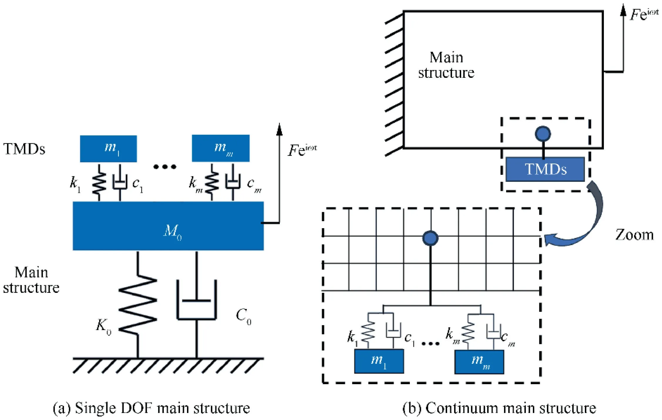
Fig.1 Schematic illustration of the main structure with attached TMDs.

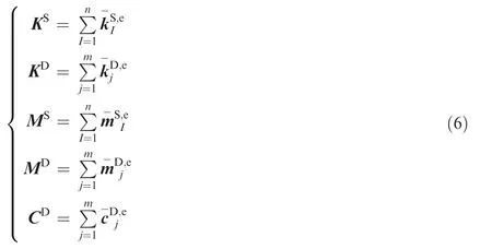
Uand Fare the displacement and force matrices,respectively.In the FEA model,the TMDs are located at a certain node of the structural elements.The global stiffness matrix K and mass matrix M are composed of those of the main structure and TMDs.While the global damping matrix C is only composed of the damping matrix of TMDs because the damping of the main structure is very small compared with that of TMDs.Thus,the K,M and C of the system are expressed as:

where the superscripts S and D represent the main structure and TMDs,respectively.K,K,M,Mand Care obtained by finite element assembly:
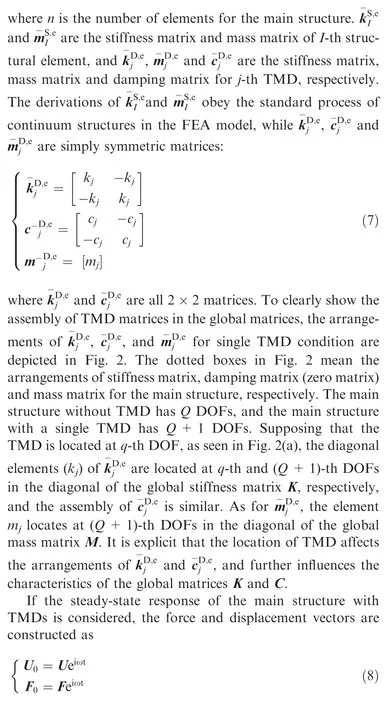


There is no doubt that the displacement field U is affected by the location and damping parameters of TMDs,and the material layout of the main structure.
3.Mathematical model
The optimization objective is to minimize the dynamic response of the main structure under harmonic excitations.Therefore,the optimization objective function is defined as the steady-state dynamic compliance of the main structure in the frequency domain,which is stated as the inner product of the excitation force and the displacement response:


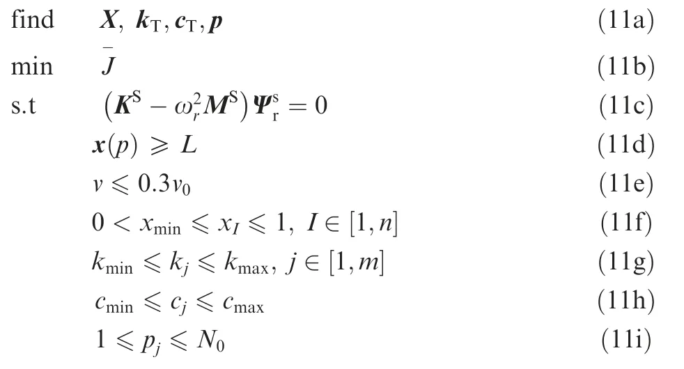

Fig.2 Assembly of in global stiffness matrix K(a),assembly of in global damping matrix C(b),and assembly of in global mass matrix M (c) for single TMD.
To optimize the main structure and the attached TMDs simultaneously,the pseudo densities of the structural elements,the damping parameters and the locations of TMDs are chosen as the design variables.The mathematical model for the optimization problem is described as whereX=[,,···x] are the pseudo densities of the structural elements,k=[,,···k],and c=[,,···c] are the unions of the stiffness and damping of TMDs,respectively.p=[,,···p]are the union of the attached structural node numbers in the finite element model,and represent the TMDs’locations.Eq.(11c) is the modal equilibrium equation of the main structure without TMDs,which is necessary for the determination of the TMDs’ locations.It should be noticed that the surroundings of the TMDs’locations must have material,so the pseudo densities of the main structure around TMDs should be constrained,which is represented by Eq.(11d),whereis defined as the lower limit value of pseudo density around TMD’s position p.Eq.(11e) indicates the volume constraint of the main structure,and Eqs.(11f)-(11i)denote the lower and upper limit constraints of the design variables.andare the minimum and maximum values of TMD stiffness,respectively.andare the minimum and maximum values of TMD damping,respectively.represents the largest node number in the finite element model for the main structure.Eq.(11i) indicates that for a single TMD’s position p,the TMD may be located at any structural node in the finite element model for the main structure.
4.Design flow
4.1.Multi-level optimization frame
To combine the structural TO with the optimal tuning of TMDs and take account of the interactions between each other,a multi-level optimization frame is proposed as shown in Fig.3.The optimization frame contains two levels,in which level 1 is the TO of the main structure,and level 2 is the optimal tuning of the TMDs.Level 2 is nested inside level 1,which signifies that the locations and damping parameters of TMDs are optimized in every loop of TO of the main structure.
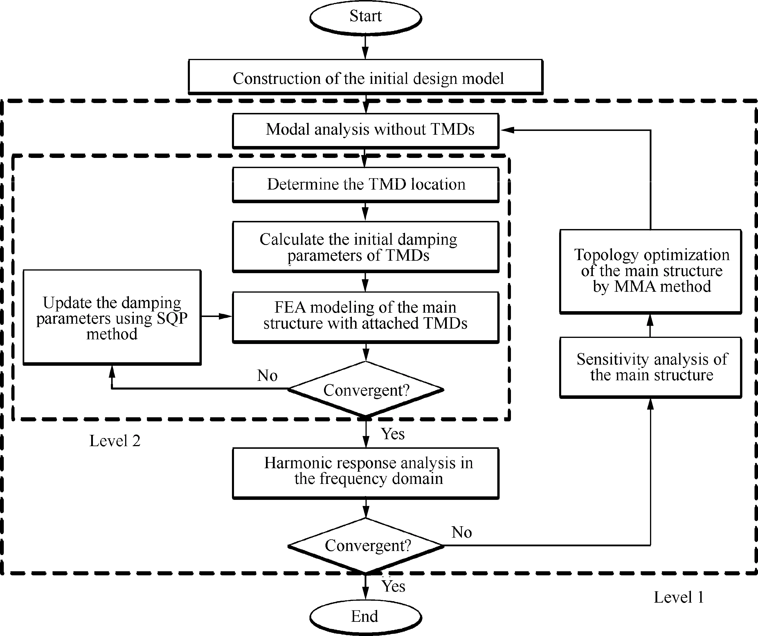
Fig.3 Flowchart of the multi-level optimization frame.
The optimization procedure starts with the initialization of the design model,and then enters a TO loop of the main structure.In the TO loop,modal analysis of the main structure without TMD is conducted first,and then the TMD optimum tuning level loop starts.In the process of TMD tuning,The TMDs’locations are determined first based on the modal analysis result of target mode in the current TO step.Then the current initial damping parameters of TMDs are calculated,and the damping parameters are optimized and updated using the Sequential Quadratic Programming (SQP) method.The procedure exits the optimal tuning loop when the convergent condition of the SQP optimization is satisfied.The detailed optimal tuning of TMDs,including the determination of TMDs’locations and optimization of the damping parameters,is described in Section 4.3.After the locations and damping parameters of the TMDs are determined,the harmonic analysis of the main structure with attached TMDs is conducted,and the dynamic compliance of the main structure in the frequency domain is obtained.Next,the sensitivity with respect to the topological variables of the main structure is analyzed.The topological variables are updated utilizing the MMA method,and then the optimization procedure goes to the next TO loop of the main structure.The TO loop comes to end until the iteration convergence condition is reached.The iteration stops when either of the following criteria is satisfied:(1) the change of the objective function of three successive iterations is smaller than the convergence tolerance ε;(2) the iteration process reaches the maximum iteration number IN.
4.2.Topology optimization of the main structure
SIMP method is adopted to optimize the material layout of the main structure.To avoid phenomena of localized modes caused by the interpolation scheme of SIMP in TO for dynamic problems,Polynomial Interpolation Scheme (PIS)is adopted for the interpolation scheme of the main structure,which is expressed as

where x∈[,1] is the pseudo density of the-th element of the main structure.=0.001 is defined as the lower bound of the topological variable to avoid the numerical singularity of the matrix.The location and damping parameters of TMDs are regarded as the discrete design variables,and there is no numerical interpolation.
The sensitivity of the objective function with respect to the topological variables of the main structure is analyzed by the adjoint method.Making S=K+iωC-ωM,and then

The dynamic compliance function can be rewritten as

The derivative of Eqs.(13) and (14) with respect to the topological variable xis
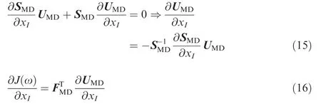
Substituting Eq.(15)into Eq.(16),the sensitivity is derived as follows

Then the sensitivity with respect to the topological variable is

Substituting Eq.(12) into Eq.(18),and the sensitivity is finally derived as follows

where uis the displacement matrix of-th structural element.
4.3.Optimal tuning of the TMDs
To determine the optimal tuning of TMDs in the continuum system,the equivalent modal mass of the main system is calculated first by adding a mass block to the position where the TMD is attached and is calculated by


After the TMDs’ location is determined,the equivalent modal mass Mand the mass ratio μ in the current step of TO loop are calculated.The SQP method is adopted to optimize damping parameters.For the single TMD condition,the mathematical model for optimal tuning of damping parameters can be stated as:whereis the maximum dynamic compliance of the main structure of the target mode to be damped.The initial values of kand care determined by Eq.(3).Through the above approaches,the optimal locations and damping parameters of the TMDs are worked out.

5.Numerical examples
To validate the suggested design optimization method,two cantilever structures with different load conditions are presented.To avoid the checkerboard phenomenon,the sensitivity filter methodis adopted,and the GCMMA (Globally Convergent Method of Moving Asymptotes) algorithmis applied as the optimizer,which is widely adopted to deal with TO problems with high efficiency.The material of the main structure is steel (=1.3×10Pa,ρ=7800 kg/m,ν=0.3).The convergence tolerance ε and the maximum iteration number IN are defined as 4×10and 400,respectively.The lower limit value of pseudo densityin Eq.(11d) is 0.6.The values of,,,andin Eqs.(11 g)-(11 h)are 1×10N/m,1×10N/m,100 N·s/m,and 2000 N·s/m,respectively.The mass of the single TMD is preset as 2 kg.It should be noted that only the structural dynamic performance is considered in this paper.
To avoid the extreme amplitude at the resonance of the main structure without TMD,the main structure is considered to have a small modal damping ratio,which is defined as 0.001.The low modal damping ratio has little influence on the optimal tuning of TMD with the help of numerical optimization.
5.1.Cantilever structure with harmonic load at the center of the free edge
The cantilever structure subjected to a harmonic loadwith 100 N amplitude along the negative-axis at the center of the free edge is shown in Fig.4.The structural size is 1 m×0.5 m with 0.01 m thickness.Considering the loading symmetry,two TMDs with the same damping parameters and mass are located at the symmetrical positions in the upper and lower parts of the main structure.The first mode of the main structure is set to be the target mode to be damped with TMDs,and the TMDs are all acted in the-axis direction according to the direction of load.The excitation frequency range is 0-350 Hz (ω=350 Hz).
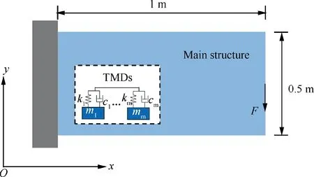
Fig.4 Illustration of the cantilever structure with attached TMDs.
Fig.5 signifies the optimization process of the TO results of the cantilever structure together with the locations of the TMDs.represents the iteration number,and the stars indicate the TMDs’ locations.As shown in Fig.5,with the proceeding of the TO of the main structure,the locations of two TMDs are varied,and the damping parameters are also updated accordingly.This is because the modal shape of the structure is changed with the updating of the TO result.At the beginning of the TO process,the TMDs are located at the center of the upper and lower sides,and then they move towards where the harmonic loadapplied.The final TO result and the TMDs’ locations are illustrated in Fig.5(f),and the TMDs are located at the symmetrical positions of the left side near the harmonic load.In the optimization process,the TO result of the main structure and the layout of the attached TMDs are mutually affected by each other.The optimization process iterates 336 steps to reach the convergence as shown in Fig.6(a),and the final TMD stiffness and damping are 7.80×10N/m and 512.5 N·s/m,respectively.The dynamic compliance of the structure in the frequency domain is expressed in Fig.6(b),and the maximum dynamic compliance is 5.09×10J.After optimization,the modal analysis results are obtained as shown in Fig.7.The first mode of the optimized main structure without TMDs is shown in Fig.7(a),which is the target mode to be damped.Fig.7(b) presents the lowest three modes of the optimized main structure with TMDs,and the three corresponding eigenfrequencies are 293.4 Hz,312.7 Hz and 339.5 Hz,respectively.What needs to concern is that the three modes are all originated from the mode as shown in Fig.7(a) under the impact of two TMDs.As seen in Fig.7(b),the first and third modes have similar mode shapes,which behave yawing at the right side,and the two modes are similar to the mode in Fig.7(a).While the second mode is different,which has no yawing behavior near the harmonic force,and therefore there is no resonance when the excitation frequency is close to the second eigenfrequency as shown in Fig.6(b).
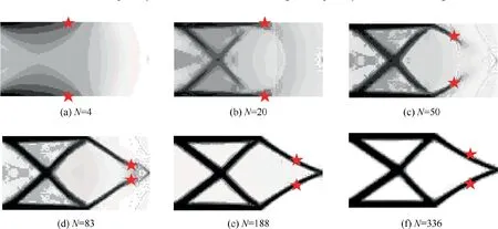
Fig.5 Optimization process of cantilever structure with two TMDs.
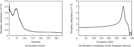
Fig.6 Optimization results of cantilever structure with two TMDs.
To demonstrate the superiority of the proposed optimization method,the cantilever structure is redesigned by the traditional design method with a non-simultaneous optimization strategy.In the traditional design method,the TO of the cantilever structure is performed first,then the two TMDs with the same mass are located at the symmetrical positions where the largest target modal displacement happens,and then the damping parameters are optimized through optimal tuning.Fig.8 shows the optimization results obtained by the proposed design method and the traditional design method.The optimal TMD stiffness and damping resulted from the traditional method are 7.30×10N/m and 361.0 N·s/m,respectively,as listed in Table 1.As seen in Fig.8,the TMDs’ locations and the TO results of the two cases are different.Compared with the result obtained by the proposed method,the TMDs’ locations are more close to the harmonic load,and the shape of the cross part in the structure is different.To investigate the influence of TO result on the structural performance,the modal analysis without TMDs of the first mode (the target mode to be damped) for the design result from the traditional method is shown in Fig.9(a),and the same mode of the design result from the proposed method as shown in Fig.7(a) is redrawn in Fig.9(b) for comparison.As seen in Fig.9,the distribution of modal strain energy of the two results are different,in which the modal strain energy is more concentrated in the result obtained by the proposed design method.Therefore,the attached TMDs can achieve better damping performance.The dynamic compliance of the main structure in the frequency domain of the two cases are illustrated in Fig.8,and the maximum compliance in the traditional method is 1.15×10J.Compared with the result of the traditional design method,the maximum dynamic compliance is significantly decreased by 55.7%.The optimization results indicate that when the cantilever structure and TMDs are optimized simultaneously by utilizing the proposed design method,the dynamic performance is superior to that obtained by the traditional design method.
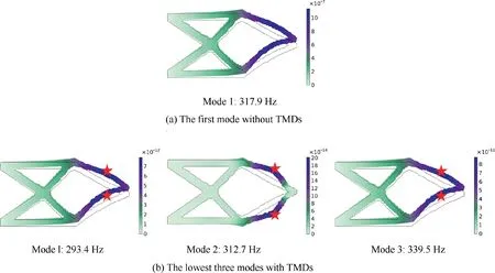
Fig.7 Modal analysis results of the cantilever structure.
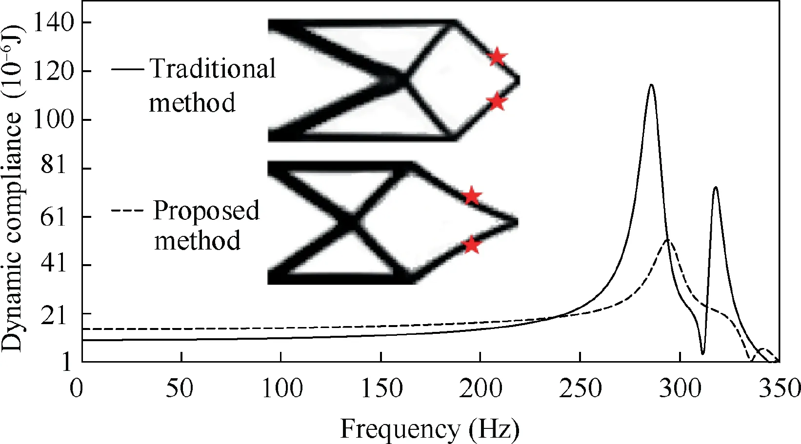
Fig.8 Optimization result comparison of cantilever structure obtained by traditional method and proposed method.

Table 1 TMD damping parameters and dynamic performance comparisons for cantilever structure.

Fig.9 Modal analysis comparison of the first mode for optimized structure without TMDs obtained by traditional method and proposed method.
To figure out the influence of TMD mass on the optimization results,the simultaneous optimization of the cantilever structure with different TMD mass is studied,and the optimization results are revealed in Fig.10 while the TMD mass is 1 kg×2,2 kg×2 and 3 kg×2,respectively.As shown in Fig.10,the TO results of the three cases are similar,and the TMDs’ locations are close as well.When the TMD mass increases from 1 kg to 2 kg,and 3 kg,the maximum dynamic compliance decreases from 6.20×10J to 5.09×10J,and 4.43×10J,respectively.Therefore,the dynamic performance is improved as the TMD mass increases.Table 2 lists the damping parameters of TMDs for the three cases.As seen in Table 2,when the TMD mass increases,the TMD stiffness and damping are increased as well,and the eigenfrequencies are decreased correspondingly.It should be noticed that the TMD mass should be chosen reasonably to consider the eigenfrequency limitation in practical applications.
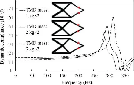
Fig.10 Influence of TMD mass on dynamic performance.

Table 2 TMD damping parameters and dynamic performance for different TMD mass.

Table 3 TMD damping parameter and dynamic performance comparisons for cantilever structure.
5.2.Cantilever structure with harmonic load at bottom corner of the free edge
The second example is the same cantilever structure subjected to a harmonic loadwith the same amplitude along the negative-axis at the bottom corner,as shown in Fig.11.Different from the first example,only one position is afforded for the location of TMDs.The first mode of the cantilever structure is set to be the target mode to be damped.Based on the direction of force,these TMDs are all acted in the-axis direction.The overall mass of TMDs is preset as 2 kg.The excitation frequency range is 0-380 Hz (ω=380 Hz).
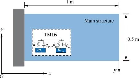
Fig.11 Illustration of cantilever structure with attached TMDs.
The simultaneous optimization of the cantilever structure together with a single TMD is conducted first.Fig.12 signifies the optimization process of the TO results of the cantilever structure together with the TMD’s location.As shown in Fig.12,the TMD’s location is also varied with the proceeding of the TO of the cantilever structure.In the initial optimization stage,the TMD is located at where the harmonic forceapplied,and then it moves upward,and then moves downward of the cantilever structure.The final TO result and the TMD’s location are illustrated in Fig.12(f),and the TMD is located at the bottom edge near the harmonic load.The final TMD stiffness and damping are 8.99×10N/m and 601.42 N·s/m,respectively.The simultaneous optimization process iterates 294 steps to reach the convergence,which is shown in Fig.13(a).The dynamic compliance of the cantilever structure in the frequency domain is expressed in Fig.13(b),and the maximum dynamic compliance is 8.38×10J when the excitation frequency is close to the first eigenfrequency.After optimization,the modal analysis results are illustrated in Fig.14.Fig.14(a) shows the first mode without TMDs,which is the target mode to be damped.Fig.14(b) presents the lowest two modes with TMDs,and the two corresponding eigenfrequencies are 330.6 Hz and 368.3 Hz,respectively.What needs to concern is that the two modes are all originated from the mode as shown in Fig.14(a) under the impact of the single TMD.The modes in Fig.14(a) and Fig.14(b) are similar,which all behave yawing near the TMD’s location.
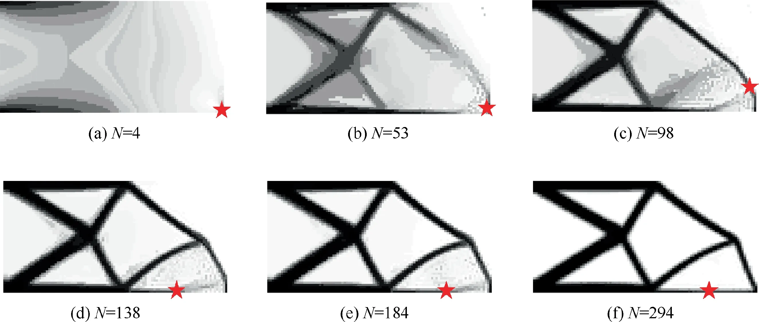
Fig.12 Optimization process of the cantilever structure with single TMD.
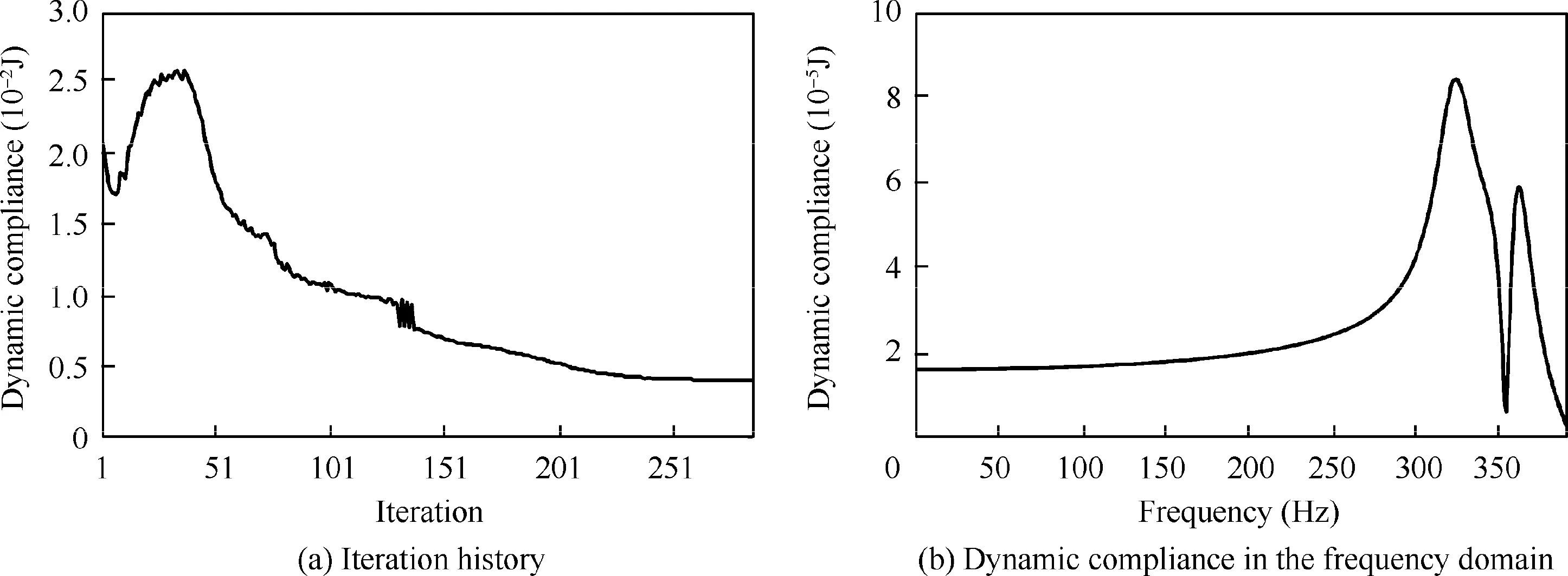
Fig.13 Optimization results of the cantilever structure.
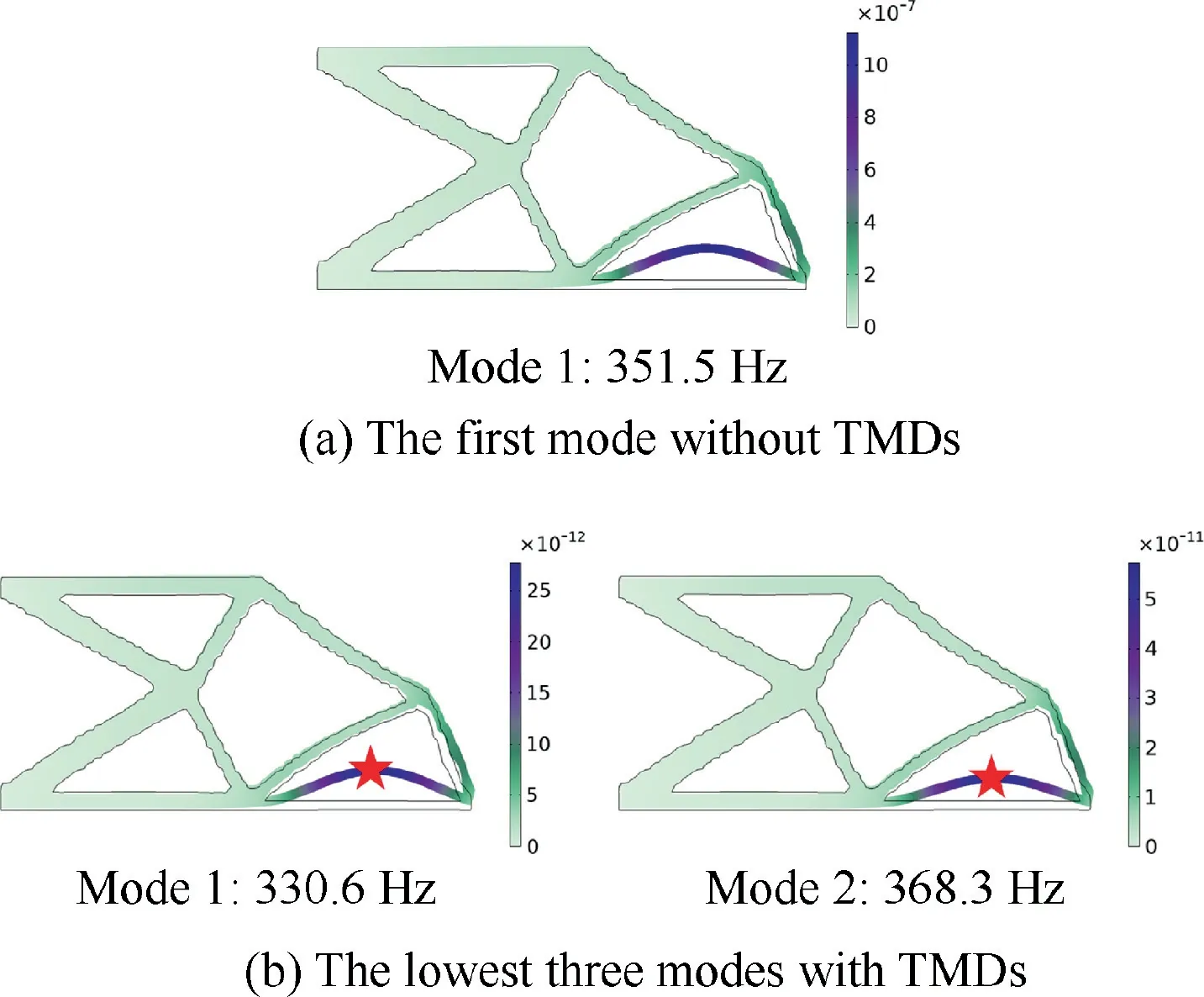
Fig.14 Modal analysis results of cantilever structure.
Fig.15 shows the comparison of the design results from the traditional method and the proposed method.The optimal stiffness and damping of the TMD obtained by the traditional method are 7.51×10N/m and 464.73 N·s/m,respectively,which are listed in Table 3.As seen in Fig.15,the TO results of the two results are different as well,which are mainly revealed in that the length ofandin the bottom edge are different,but the TMDs’ locations are similar.To analyze the influence of TO result on the structural performance,the modal analysis without TMDs of the first mode (the target mode to be damped) for the design result from the traditional method is shown in Fig.16(a),and the same mode of the design result from the proposed method as shown in Fig.14(a) is redrawn in Fig.16(b) for comparison.As seen in Fig.16,the distribution of modal strain energy of the two results are different,in which the modal strain energy is more concentrated in the result obtained by the proposed design method.It demonstrates that the TMD in the proposed method can achieve better damping performance.The dynamic compliance of the cantilever structure in the frequency domain of the two cases are illustrated in Fig.15,and the maximum compliance obtained by the traditional method is 1.61×10J.The maximum dynamic compliance obtained by the proposed design method is decreased by 48.0% compared with that resulted from the traditional method.The results indicate that when the cantilever structure and TMD are optimized simultaneously by utilizing the proposed optimization method,the dynamic performance is significantly improved.
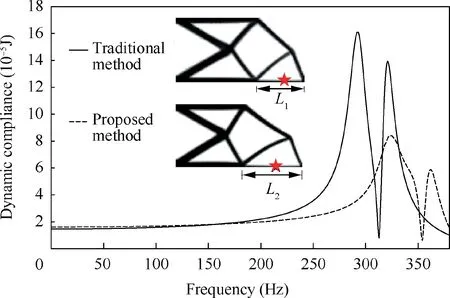
Fig.15 Optimization result comparison for the second cantilever structure.

Fig.16 Modal analysis comparison of the first mode for the optimized structure without TMDs obtained by traditional method and proposed method.
Next,the simultaneous dynamic optimization of the cantilever structure together with two TMDs with the same total TMD mass are studied.Each mass of the two TMDs is 1 kg,and the two TMDs are located at the same position with different damping parameters.The optimization results for the conditions of single TMD and two TMDs are compared in Fig.17.As seen in Fig.17,the TO results for the two cases are different due to the different structural angles of αand α,but the TMDs’ locations are similar.The optimal stiffness and damping parameters for the case with two TMDs are=4.01×10N/m,=4.57×10N/m,=167.37 N·s/m and=188.72 N·s/m,respectively.The lowest 3 eigenfrequencies are 306.6 Hz,329.6 Hz and 347.0 Hz,respectively,which are all originated from the first mode without TMDs due to the impact of two TMDs.As depicted in Fig.17,the maximum dynamic compliance for the case with two TMDs is 7.62×10J,which is decreased by 9.0% compared with that resulted from the case with single TMD.It could be found that when the TMD number increases and the total TMD mass keeps the same,the dynamic performance is improved in the simultaneous optimization cases.The summary of the TMD parameters and dynamic performance for the cantilever structure are listed in Table 3.
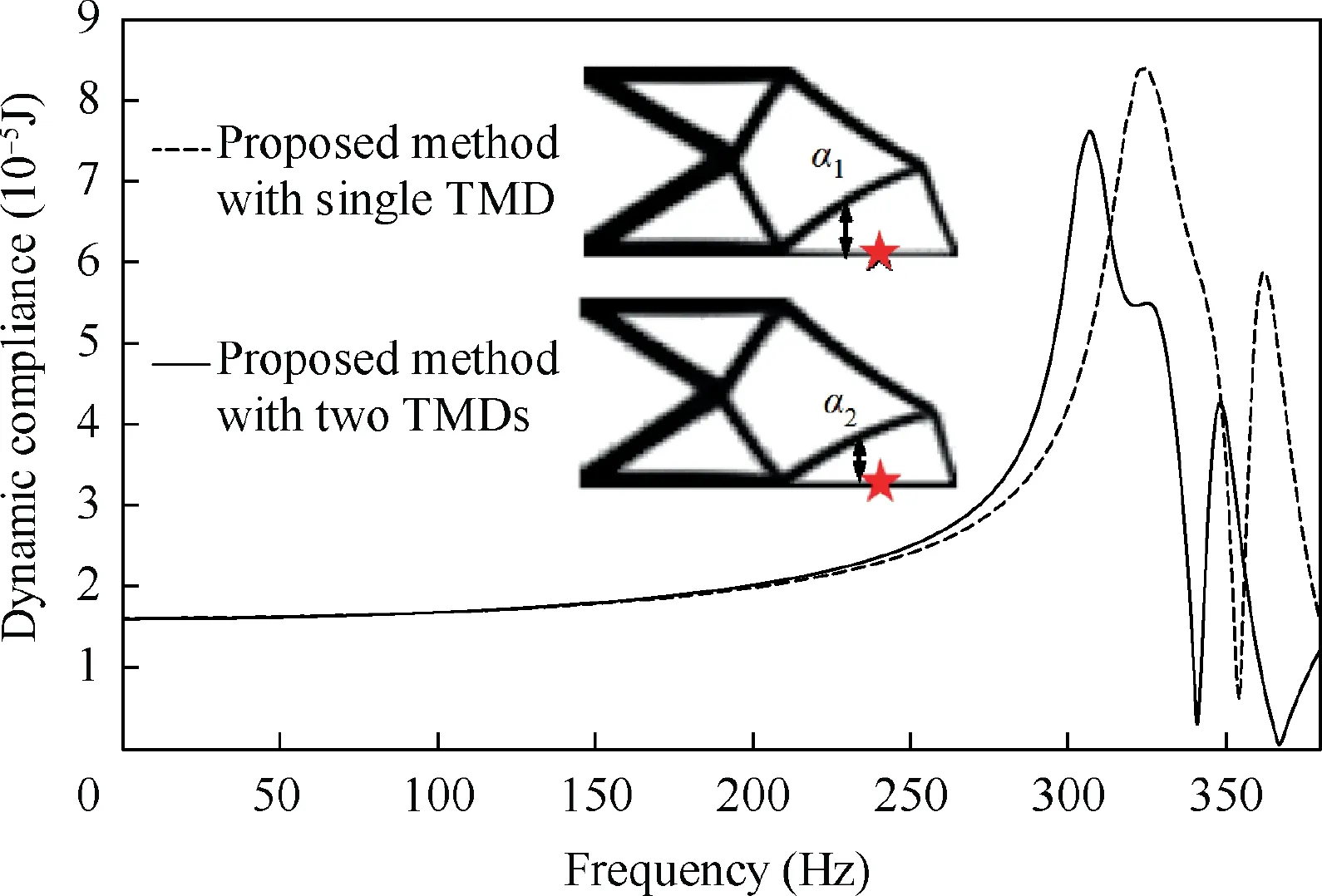
Fig.17 Optimization result comparison for different TMD numbers.
6.Conclusions
To further improve the structural dynamic performance,the main structure with the attached TMDs are optimized simultaneously by the suggested multi-level optimization approach,in which the locations and damping parameters of TMDs are optimized in every loop of TO of the main structure.By this method,the interactions of the main structure and attached TMDs can be fully considered to improve the structural dynamic performance under harmonic excitation.
Optimization results obtained by the numerical examples indicate the superiority of the proposed design optimization method.Compared with the results from the traditional nonsimultaneous optimization approach,the modal strain energy of the target mode for the optimized main structure is more concentrated at the largest modal displacement,therefore the TMDs can achieve better damping performance,and the dynamic compliance of the target mode is dramatically reduced.The effects of TMD number and TMD mass on the optimization results are also investigated.While the TMD mass increases,the dynamic performance is improved as expected,and the TO results and TMDs’ locations keep unchanged.In the meantime,the eigenfrequency limitation of main structures should be considered when the TMD mass increases.When the TMD number increases and the total mass of TMDs is constant,the dynamic performance is improved.The proposed design optimization method provides an effective guide to design structures together with TMDs in practical applications,such as aeronautics engineering,machine tool industry and engineering structures to improve the dynamic performance.
The authors declare that they have no known competing financial interests or personal relationships that could have appeared to influence the work reported in this paper.
The research is co-supported by the National Natural Science Foundation of China (Nos.51975380 and 52005377) and China Postdoctoral Science Foundation,China (No.2020M681346).
