High RF power tests of the first 1.3 GHz fundamental power coupler prototypes for the SHINE project
Zhen-Yu Ma • Shen-Jie Zhao • Xu-Ming Liu • Yue-Chao Yu • Hong-Ru Jiang • Xiang Zheng • Qiang Chang • Zi-Gang Zhang • Kai Xu • Yan Wang • Yu-Bin Zhao • Hong-Tao Hou
Abstract The Shanghai High Repetition Rate XFEL and Extreme Light Facility (SHINE) project will use 600 1.3 GHz fundamental power couplers,which are modified based on TTF-III power couplers,for continuous-wave operation with input power up to approximately 7 kW.The first batch of 20 sets of 1.3 GHz coupler prototypes was fabricated from three domestic manufacturers for the SHINE project.To better characterize the radio frequency conditioning phenomena for validating the performance of power couplers,a room temperature test stand was designed,constructed,and commissioned for the SHINE 1.3 GHz power couplers.In addition,a horizontal test cryostat was built to test the 1.3 GHz superconducting cavities,fundamental power couplers,tuners,and other components as a set.The results of these tests indicate that the 1.3 GHz couplers are capable of handling up to 14 kW continuous waves.Herein,the main aspects of the radio frequency design and construction of the test stand,along with the test results of the high-power conditioning of the 1.3 GHz couplers,are described.
Keywords Superconducting accelerating cryomodule ·1.3 GHz fundamental power coupler · RF conditioning ·Test bench · Horizontal test cryostat
1 Introduction
The Shanghai HIgh repetition rate XFEL aNd Extreme light facility (SHINE),which is under construction,is the first hard X-ray-free electronic laser facility in China[1-3].The SHINE facility will build a superconducting linear accelerator with 8 GeV energy,three undulator lines,three beamlines,and the first 10 experimental stations [4].The linear accelerator contains 75 superconducting cryomodules that have 600 1.3 GHz 9-cell TESLA-type superconducting cavities used for electron beam acceleration and two third-harmonic superconducting cryomodules,which have 16 3.9 GHz superconducting cavities used for linearizing the longitudinal phase space distortion of an electron bunch [5-9].
Fundamental power couplers(FPCs)are one of the most important components of superconducting cryomodules.The SHINE 1.3 GHz FPCs are modified and optimized based on the design of the TTF-III FPC to meet the needs of the SHINE project[10-12].The antenna of the cold part was shortened by 8.5 mm to achieve a higher external quality factorQext.The copper plating thickness on the warm inner conductor was increased to 150 μm to alleviate overheating in the continuous wave (CW) mode.The coaxial conversion waveguide was directly machined from a single block of aluminum,eliminating the radio frequency (RF) matching posts and allowing for precision alignment.In addition,the capacitor ring used for the bias voltage was replaced by a copper flex ring to provide a better RF seal between the waveguide and coupler body.Another change is the use of a stepper motor to remotely adjust the coupling for various beam loadings and to compensate for the change in the coupling due to heating of the inner conductor.The mechanical design of the SHINE 1.3 GHz FPC is shown in Fig.1.The main technical parameters of the 1.3 GHz FPC are listed in Table 1.

Table 1 Main technical parameters of the SHINE 1.3 GHz FPC

Fig.1 (Color online)Mechanical design of the SHINE 1.3 GHz FPC
TheQextof the superconducting cavity and power requirements can be calculated using Eqs.(1)-(3) and are related to some parameters,such as the coupling coefficientβ,beam currentIb,cavity intrinsic quality factorQ0,cavity voltageVc,R/Qof the cavity,frequency detuningδf,and resonant frequencyf0[13].For the SHINE project,the optimalQextof the 1.3 GHz superconducting cavities is 4.12×10⁷,under the following working conditions:the average linac beam current is 0.3 mA,the nominal accelerating gradientEaccof the 1.3 GHz superconducting cavity is 16.0 MV/m,the cavity intrinsic quality factorQ0is 2.7×10¹⁰,and the frequency detuningδfcaused by the peak microphonics effect is 10 Hz [14,15].The required input power from a solid-state amplifier (SSA) for maintaining the operating gradient is approximately 6.6 kW,considering a waveguide transmission loss of 15%.Thus,the 1.3 GHz FPC is designed to withstand a CW power of 7 kW with full reflection.The SHINE 1.3 GHz FPC is designed with an adjustable mechanism,and the full adjustment range of the antenna is approximately 15 mm so that theQextspans from 4.0×10⁶to 1.1×10⁸.

The SHINE 1.3 GHz FPC prototypes have been under development since the middle of 2018.At present,the first batch of 20 sets of 1.3 GHz FPC prototypes has been fabricated by three domestic manufacturers and high RF power-tested.The remainder of this paper is organized as follows.In Sect.2,the surface preparation procedures of the 1.3 GHz FPCs are briefly introduced.In Sect.3,the RF design of the room temperature test bench for 1.3 GHz FPCs and the RF test results are presented.In Sect.4,the off-resonance high RF power conditioning and operation of the 1.3 GHz FPC prototypes in the cryomodule are presented.Finally,the study’s conclusions are presented in Sect.5.
2 FPC preparation procedures
Prior to assembly on the room temperature test bench,the FPCs need to be cleaned to ultra-high vacuum standards to make the RF conditioning faster and more efficient[16].All FPC parts were initially cleaned in an ultrasonic bath for 30 min,followed by rinsing with ultrapure water until the resistivity of the draining water exceeded 14 MΩ·cm in class 10 cleanroom.All rinsed FPC parts were blown dry using filtered high-purity nitrogen gas.Before assembly,each FPC part is blown with filtered high-purity nitrogen gas again using a particle counter,which must count less than 10 particles of size >0.3 microns per cubic foot;if not,the FPC parts must return to the ultrasonic bath[17].A vacuum leak test was performed on the assembled FPCs,and the helium leak detection sensitivity of the system was better than 1.0×10⁻⁹mbar·L/s.
It was found that baking reduces the conditioning time by almost a factor of two;furthermore,it provides better vacuum levels in FPCs prior to conditioning compared with non-baked FPCs [18].The assembled FPCs were baked under vacuum using a modified baking oven,which was operated via a computer and a programmable logic controller.Our standard baking procedure was applied:increasing the temperature with a gradient of 10 °C/h,and maintaining a temperature of 150°C for 72 h to ensure that all water vapor was removed.Next,it was cooled down to room temperature with a controlled gradient of 10 °C/h.During the baking of FPCs,the temperatures were monitored,and the gas species were also analyzed via a residual gas analyzer.The vacuum and residual gas analysis results after the baking of the FPCs are listed in Table 2.

Table 2 Vacuum and residual gas analysis results after FPC baking
3 High RF power tests in the room temperature test bench
The FPCs need to be fully high-RF-power-conditioned at room temperature prior to installation with the superconducting cavities in the cryomodules.This allows to test the robustness of the couplers,condition away residual absorbed gases,and ‘‘burn-off’’ microscopic surface imperfections.
3.1 Composition of room temperature test system for 1.3 GHz FPCs
The high RF power test system of the 1.3 GHz FPCs mainly includes four major subsystems:(1) power source system,(2) power transmission system,(3) test bench,and(4) low-level control system [19,20].Figure 2 shows the composition block diagram of the high RF power test system for the 1.3 GHz FPCs.
The power source system is composed of an SSA capable of outputting a 30 kW CW power.The power transmission system is composed of various transmission waveguides,circulators,water-cooled RF-absorbing loads,short-circuit plungers,etc.One RF-absorbing load connected to the circulator is used to absorb the RF power reflected from the test bench to protect the power source,and the other RF-absorbing load is used to absorb all the RF power reaching the terminal.A movable short-circuit plunger is used in the standing wave (SW) mode to ensure that each position along the FPCs is fully conditioned.In addition,the incident power and reflected RF power were measured using directional couplers.The test bench included a pair of back-to-back FPCs and a rectangular connection waveguide.Two ARC detectors are installed near the ceramic windows to detect arc events,while six electron pick-up probes are installed on the outer conductors of the FPCs to monitor the current and location of secondary electrons.Ten thermocouples are used to monitor the surface temperature of the FPCs,and two IR sensors are used to measure the temperature of the warm ceramic RF windows.
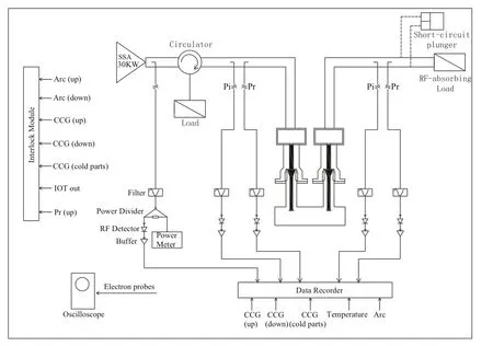
Fig.2 The composition block diagram of the high RF power test system for the 1.3 GHz FPCs
The low-level control system is used to monitor the incident power,reflected power,temperature,vacuum,electron current,ARC,and other signals.It also incorporates important signals into the interlocking system.Once the interlocking signals exceed the thresholds,the power source is cut off in the shortest time to protect the FPCs[21].Table 3 lists the thresholds for different interlocking signals.For vacuum events exceeding 5.0×10⁻⁶mbar,the RF power is cut immediately and recovered when the vacuum pressure is lower than 1.0×10⁻⁷mbar.Real-time LabView software provides the operator interface to change the RF mode parameters and control the RF testing.

Table 3 Thresholds of the different interlocking signals for the 1.3 GHz FPC RF conditioning
3.2 RF design of 1.3 GHz FPC test bench
The RF power transmission of the test bench is described as follows:the transverse electromagnetic (TEM)mode in the coaxial line of the upstream FPC is coupled to the rectangular connection waveguide via the antenna,and the transverse electric (TE10) mode is excited in the waveguide.Then,the power is transmitted from the rectangular waveguide to the downstream FPC via the antenna and continues to be transmitted forward in the downstream FPC in the form of the TEM mode and finally reaches the terminal RF absorbing load.
The focus of the RF design is to achieve good RF matching and avoid power reflection for the test bench.The goal ofS-parameter optimization is to make the reflection coefficient as small as possible and the transmission coefficient as large as possible at the operating frequency.The rectangular connection waveguide of the 1.3 GHz FPC test bench was optimized based on a half-height WR650 waveguide,in which the width is 165.1 mm and the height is 41.3 mm,as shown in Fig.3a.Three structural parameters should be optimized:the insertion depth of theantennash,the distance between the antenna and the shortcircuit surface of the waveguided1,and the distance between the two antennas of FPCsd2,as shown in Fig.3b.
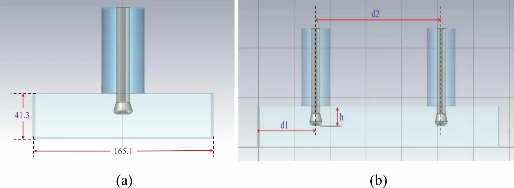
Fig.3 (Color online) The rectangular connection waveguide structural size a and structural parameters b of the 1.3 GHz FPC test bench
The optimal structural parameter combination was finally confirmed via numerous simulations and calculations:h=18.25 mm,d1=63 mm,d2=175 mm.With this combination,the test bench with the FPC antennas can achieve the best matching.Figure 4 shows theS-parameter curves for the optimized test bench in the 1.25-1.35 GHz frequency range.The optimal transmission coefficientS21≈ -0.0015 dB and the reflection coefficientS11≈-54.28 dB for the test bench at 1.3 GHz frequency are obtained.

Fig.4 (Color online) S11 and S21 parameter curves versus frequency for the optimized test bench
The errors introduced from the fabrication and installation of the FPCs will lead to the deterioration of transmission matching.A simple and feasible method is to adjust the insertion depth of the antennas to achieve a new matching.Therefore,it is necessary to further analyze the influence of insertion depthhon theSparameters.The antenna insertion depth can be adjusted up to ± 10 mm,i.e.,hchanges from 8.25 to 28.25 mm,and theS11peak frequency changes from 1.3396 to 1.2152 GHz,as shown in Fig.5.Evidently,theS-parameter peak frequency can be modulated to 1.3 GHz by adjusting the insertion depth to achieve the best match.
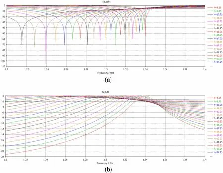
Fig.5 (Color online) S11 a and S21 b parameter curves versus frequency for different antenna insertion depths
3.3 High RF power conditioning and testing of the 1.3 GHz FPC prototypes
It is better to measure theSparameters and adjust for matching before the high RF power conditioning of FPCs.The optimal measured values ofS11andS22are-42.84 dB and-55.35 dB,respectively,and those ofS21andS12are-0.0928 dB and-0.0936 dB respectively,as shown in Fig.6.From theS21measurement,the power loss in the two FPCs and the rectangular connection waveguide in total will be 21 W for an input power of 1 kW.

Fig.6 (Color online) The measured S parameters versus frequency for the 1.3 GHz FPC test bench
To maintain the stable operation of the FPCs,the FPCs should be able to transmit RF power significantly higher than 6.6 kW on the test bench.In general,the target value of RF conditioning is twice that of the required power[22,23].In addition,we considered a special situation.If a cavity ‘‘quenches’’ in operation or trips for some other reason,all the forward power in the FPC is reflected and the FPC ‘‘sees’’ local peak power between a minimum value and four times the input power level [24].We have established the RF test specifications for the SHINE 1.3 GHz FPC prototypes,as shown in Table 4,to better evaluate the manufacturing techniques and performance of the FPCs.

Table 4 RF test specifications for the SHINE 1.3 GHz FPC prototypes
The FPCs were RF-conditioned in both the traveling wave (TW) and SW modes.First,the conditioning was started in TW pulse mode,and the RF power was pulsemodulated with a 1 ms pulse length and 100 ms repetition period.The peak power was increased from 1 to 28 kW with an increase of 0.5 kW per step.Any deterioration of the vacuum close to the threshold resulted in a power reduction.The maximum power was maintained for half an hour.Then,the peak power was decreased to 1 kW,and the same operation was repeated with a larger pulse width of 2,4,8,10,15,and 20 ms in sequence.Once the pulse conditioning was finished,CW conditioning started from 1 kW and increased to 14 kW,with an increase of 0.5 kW per step.Finally,it was maintained at a 14 kW CW power level for six hours.A variation of 170 mm can be achieved by moving the short-circuit plunger in the SW mode,ensuring that all areas of the FPCs are exposed to the maximum electric field.The RF conditioning procedure for the SW mode was similar to that for the TW mode and was maintained at a CW power level of 7 kW for twelve hours.
A total of 20 sets of 1.3 GHz FPC prototypes were all RF-conditioned,and all of them successfully passed the high RF power tests on the room temperature test bench.Figure 7 shows the SHINE 1.3 GHz FPC test system.Here,we list the test results for one pair of FPCs as an example.Figure 8a shows the temperature distribution along the FPC for the power increasing from 5 to 14 kW in TW CW mode,and Fig.8b shows the temperature distribution for the power increasing from 1 to 7 kW in SW CW mode.The temperature sensor positions 2 and 5 represent the warm and cold RF window temperatures,respectively.In the 14 kW TW mode or 7 kW SW mode,the temperatures of RF windows were below the threshold of 80·C.There was no obvious temperature increase in the outer conductor bellows of the FPC or rectangular connection waveguide.Figure 9a shows the vacuum pressure in the cold and warm parts for power ranging from 5 to 14 kW in TW mode,and Fig.9b shows the vacuum variation during the six-hour 14 kW maintaining period.Figure 10a shows the vacuum pressure in the cold and warm parts for power ranging from 1 to 7 kW in SW mode,and Fig.10b shows the vacuum variation during the 12-h 7 kW maintaining period.Evidently,the vacuum gradually improved during RF testing.The electron activity was approximately 15 mV,and the temperature of the ceramic RF windows was 40-47 °C.Arcing events rarely occurred during the RF conditioning and testing.

Fig.7 (Color online) SHINE 1.3 GHz FPC high RF power test system
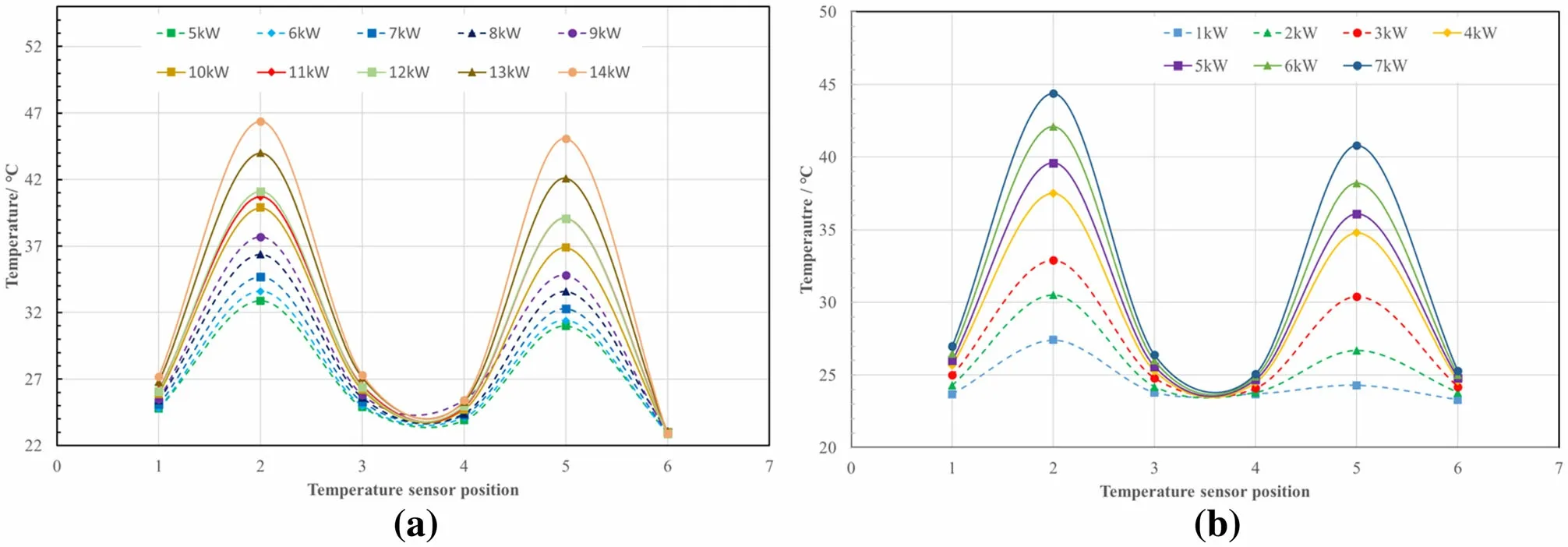
Fig.8 (Color online) Temperature distribution along the FPC for the power ranging from 5 to 14 kW in TW mode (a) and ranging from 1 to 7 kW in SW mode (b)

Fig.9 (Color online) The vacuum pressure of the cold and warm parts with the power ranging from 5 to 14 kW in TW mode (a),and the vacuum variation during the 6 h 14 kW maintaining period (b)
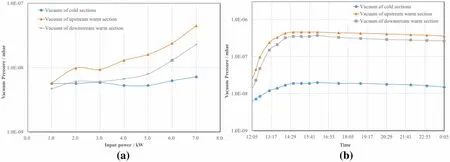
Fig.10 (Color online)The vacuum pressure of the cold and warm parts with the power ranging from 1 to 7 kW in SW mode(a),and the vacuum variation during the 12 h 7 kW maintaining period (b)
All 1.3 GHz FPC prototypes were stored under vacuum until required for installation on the superconducting cavities.After several weeks of storage under vacuum,two FPC prototypes were re-tested to verify the RF conditioning memory.The high RF power tests were completed quickly and smoothly in 11 h.It was verified that the storage method of the FPCs was effective and reliable.In addition,a pair of FPC prototypes have undergone prolonged time testing with maximum 4.5 kW SW power,which produces the same heat load as most stringent requirements of SHINE at 0.3 mA beam current operation:6.6 kW forward power with 1.6 kW reflected power(total 8.2 kW)and aQextof 4.12×10⁷.The power was maintained for 20 days without any interlocking.
4 High RF power conditioning and operation in Cryomodule
To minimize risks to the project,the most critical components and technical solutions are tested in the cryomodule under conditions approximating the final CM configuration[25,26].In this cryogenic test,eight 1.3 GHz superconducting cavities that were previously qualified in a vertical cryostat were fully assembled with all components(FPCs,magnetic shielding,feed-throughs,and tuners) in the cryomodule [27].One major goal of these integrated tests was to demonstrate that highQ0values demonstrated in vertical tests can be preserved even when additional sources of heating from the FPCs,tuners,and potential additional external magnetic fields from auxiliary components are present.Other important studies related to design verification include thermal performance and power handling of the FPCs,heating of HOM couplers and tuner components,tuner performance,sensitivity to microphonics,and frequency control.Here,we introduce only the testing results with the FPC prototypes.
4.1 Warm off-resonance RF conditioning
The first SHINE 1.3 GHz cryomodule prototype was assembled and installed in a horizontal test tunnel in February 2021,as shown in Fig.11.Eight 1.3 GHz FPC prototypes were assembled in this cryomodule.Warm offresonance high RF power conditioning of eight 1.3 GHz FPC prototypes was performed in April 2021.

Fig.11 (Color online) The first SHINE 1.3 GHz cryomodule prototype in the horizontal test tunnel
First,we started warm off-resonance high RF power conditioning for one FPC prototype to verify the function of the test system.The master frequency of the SSA was set to 1.3 GHz,and it was above the resonant frequency of the superconducting cavity by approximately 1.7 MHz,guaranteeing that the superconducting cavity was off-resonance.Under a 4.5 kW CW input power,the vacuum of the cavity changed from 1.2×10⁻⁸to 1.4×10⁻⁸mbar,and the vacuum of the FPC warm parts changed from 1.8×10⁻⁸to 2.8×10⁻⁸mbar (vacuum threshold setting:cavity vacuum was 1.0×10⁻⁷mbar,FPC warm parts vacuum was 5.0×10⁻⁷mbar).Subsequently,we started the RF conditioning of the five sets of FPCs.When the input power was 4.5 kW,the temperature of the warm RF windows of the FPCs was in the range of 40-50 °C,the vacuum of the cavity changed from 1.3×10⁻⁸to 1.9×10⁻⁸mbar,and the vacuum of the FPC warm parts changed from 1.6×10⁻⁸to 1.1×10⁻⁷mbar.The remaining two sets of FPCs completed RF conditioning with the same operation.Figure 12 shows the vacuum variation of the cavity and FPC warm parts with power ranging from 1 to 4.5 kW for the eight FPCs.Figure 13 shows the temperature variation of warm RF windows and CF100 flanges of FPCs with power ranging from 1 to 4.5 kW.The maximum temperature increase of the CF100 flange of the FPCs was approximately 25 K.No arc events and electron activities occurred during the warm off-resonance high RF power conditioning.
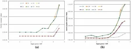
Fig.12 (Color online) Vacuum variation of the cavity (a) and FPC warm parts (b) during the warm off-resonance RF conditioning
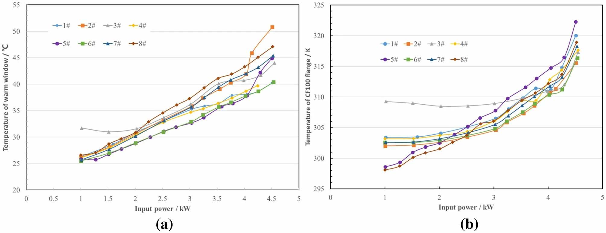
Fig.13 (Color online) Temperature variation of warm RF windows (a) and CF100 flanges (b) of FPCs during the warm off-resonance RF conditioning
4.2 Cold off-resonance RF conditioning and operation
Cooling of the first 1.3 GHz cryomodule prototype to 2 K began in July 2021 and was completed in a few days.First,we measured and adjusted the loaded quality factorQLof the cavities to a design value of 4.1×10⁷.Two methods were used to measure theQLof the cavities.One method was to approximately measure theQLdirectly using a coaxial waveguide and network analyzer.The other method used the power attenuation method for accurate measurement.TheQLmeasurement values of the eight superconducting cavities are listed in Table 5.The errors produced by the two methods did not exceed 10%.Owing to the connection problem of the driving rod,the No.8 FPC cannot be adjusted,but it did not influence the subsequent high RF power conditioning.

Table 5 Measurement values of QL for the eight superconducting cavities in the first SHINE 1.3 GHz cryomodule prototype
Owing to the limited test time given by the cryogenic system,the FPCs were only RF conditioned up to the power level,which was sufficient for the horizontal tests of the superconducting cavities.All FPCs were RF-conditioned up to 2.5 kW and the eighth FPC was RF conditioned up to 3.5 kW.First,we started the 2 K offresonance RF conditioning for one set of 1.3 GHz FPC prototypes.Then,three sets of FPCs and four sets of FPCs were separately conditioned together.Figure 14 shows the vacuum variation of the cavities and FPC warm parts with power ranging from 0.5 to 2.5 kW for the eight FPCs.Figure 15 shows the temperature variation of the warm RF windows and CF100 flanges of FPCs with power ranging from 0.5 to 2.5 kW.When the input power was 2.5 kW,the maximum temperature of the warm RF windows of the FPCs increased to 45°C.When the input power of the No.8 FPC was 3.5 kW,the temperature of the warm RF window increased to 55°C without any cooling.Under 2.5 kW input power,the cavity vacuum changed from 4.5×10⁻⁹to 4.3×10⁻⁹mbar,and the vacuum of the FPC warm parts changed from 9.0×10⁻⁹to 1.0×10⁻⁸mbar.The vacuum was less affected by the high RF power conditioning at 2 K.It took 19 h to finish the cold off-resonance RF conditioning for the eight 1.3 GHz FPC prototypes,without any interlocking.
During the first horizontal tests of the integrated cryomodule prototype,the maximum input power for establishing the 16 MV/m accelerating gradients of the superconducting cavities was approximately 1.6 kW.Vacuum,temperature,electron activities,and arcing events were recorded,and the eight 1.3 GHz FPC prototypes worked well.
4.3 Heat flux measurements at 5 K and 45 K zones
FPC thermal intercepts comprising flexible copper braids were installed to provide effective cooling for the FPC.One copper braid connected the FPC CF100 flange to the cryomodule’s 45 K helium pipe.The other copper braid connected the 5 K intercept to the 5 K helium pipe.A cryogenic thermal paste was used to ensure good thermal conduction between the copper braids and clamping surfaces.The eight FPC prototypes had 29 thermal sensors(Cernox and PT100) to measure and monitor the FPC temperatures.These sensors were attached to the 2,5,and 45 K sections of the FPCs,in addition to the 5 K and 45 K copper braids.The heat flux of the three 1.3 GHz FPC prototypes was calculated by measuring the temperature gradient on the copper braids.Table 6 compares the measured static heat loads between the three SHINE 1.3 GHz FPC prototypes and the LCLS-II 1.3 GHz FPC prototype,which was tested using a Fermilab horizontal test stand cryostat[28].The reference values for 5 K and 45 K static heat loads were adopted from the simulation results in[28].The 5 K static loads of the SHINE 1.3 GHz FPC prototypes are slightly smaller than those of LCLS-II,but the 45 K static loads are slightly larger than those of LCLS-II.The 5 K static load of the No.8 FPC prototype was significantly different from the other two FPC prototypes,and we need to confirm whether the temperature sensor is invalid when disassembling the cryomodule at a later time.

Fig.14 (Color online) Vacuum variation of the cavities (a) and FPC warm parts (b) during the cold off-resonance RF conditioning
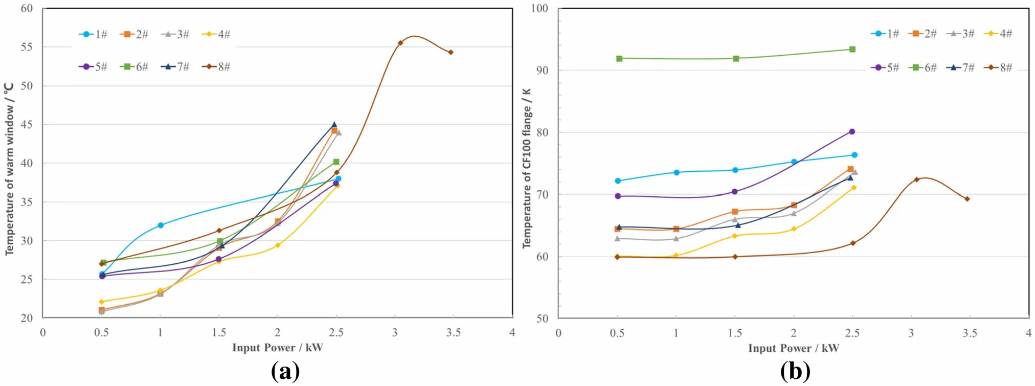
Fig.15 (Color online)Temperature variation of the warm RF windows(a)and CF100 flanges(b)of the FPCs during the cold off-resonance RF conditioning

Table 6 Measured static heat loads of the SHINE 1.3 GHz FPC prototypes and comparison with the LCLS-II 1.3 GHz FPC prototype
In this cryogenic test,we measured the heat flux for cavity off-resonance at the 5 K and 45 K zones.Additional RF losses caused by cavity on-resonance were not measured because of the limited test time.Here,we compare the measured heat flux at a 2.5 kW power level between the three SHINE 1.3 GHz FPC prototypes and the LCLS-II 1.3 GHz FPC prototype,as shown in Table 7.The heat loads of the SHINE 1.3 GHz FPC prototypes at the 5 K and 45 K zones appear to be better than the LCLS-II test result.It must be pointed out that the 45 K zones of the LCLS-II FPC prototype were connected to the cryostat’s 80 K thermal shield.This only provides a reference for us.

Table 7 Measured heat flux of the SHINE 1.3 GHz FPC prototypes and comparison with the LCLS-II 1.3 GHz FPC prototype at 2.5 kW power level
The temperature rising saturation time for all sensors installed at the 45 K zone was much higher than for those in the 300 K and 5 K zones.The time is defined by thethermal conductivity of the FPC antenna,ceramic window,massive CF100 stainless steel flange,and a large volume pure aluminum can,which is attached to the CF100 flange.It takes more than six hours of heating to be close to the equilibrium regime.In this cryogenic heat load test,the measured temperature values were recorded after one hour.We hope to obtain more accurate values in the next cryogenic tests.
5 Conclusion
The SHINE 1.3 GHz FPC was developed based on the XFEL TTF-III 1.3 GHz coupler with some modification and optimization,where the XFEL TTF-III 1.3 GHz coupler was designed for 1 MW pulsed power but generally was not operated at more than 1.5 kW average power.The extrapolation of the original test results suggests that the existing TTF-III coupler can very likely be operated up to 5 kW SW,although without direct verification [25].A room temperature test stand,the associated instrumentation for controls,and data acquisition required for RF testing of the 1.3 GHz FPCs were designed,assembled,and commissioned at the SHINE site.The first batch of 20 sets of 1.3 GHz FPC prototypes was tested on a room temperature RF test stand and transferred up to 14 kW TW and 7 kW SW,in excess of the SHINE specifications.No noticeable problems were encountered during the conditioning process.The first cryogenic horizontal test was also successful,validating the superconducting accelerating unit:1.3 GHz superconducting cavities equipped with a helium tank,with FPCs and tuners in the final cryomodule configuration.A nominal accelerating field of 16 MV/m was achieved with an input power of 1.6 kW.
For future CW accelerator projects,where beam loading is small and microphonic detuning dominates the power budget,we believe that FPCs with higher power will be required.Based on the current RF power test results of the SHINE 1.3 GHz FPC prototypes,we believe that 20 kW TW and 10 kW SW power could be achieved,and this has been included in the next research plan.In addition,an automatic RF test bench has been installed and is currently being tested.The nominal RF conditioning rate of the two couplers per week will be increased to four couplers over a few months.
AcknowledgementsWe are grateful to Dr.Yi-Yong Liu and Ya-Wei Huang of Shanghai Advanced Research Institute,CAS,for discussing the methods of static and heat flux measurements,and Dr.Li-Xin Yin and Dong Wang of Shanghai Advanced Research Institute,CAS,for their suggestions regarding the FPC test plans.We are especially grateful to Dr.Denis Kostin of DESY for his long-term help and guidance in our work.Finally,we are grateful to the SHINE cryomodule team for their hard work and efforts in this cryogenic horizontal test.
Open AccessThis article is licensed under a Creative Commons Attribution 4.0 International License,which permits use,sharing,adaptation,distribution and reproduction in any medium or format,as long as you give appropriate credit to the original author(s) and the source,provide a link to the Creative Commons licence,and indicate if changes were made.The images or other third party material in this article are included in the article’s Creative Commons licence,unless indicated otherwise in a credit line to the material.If material is not included in the article’s Creative Commons licence and your intended use is not permitted by statutory regulation or exceeds the permitted use,you will need to obtain permission directly from the copyright holder.To view a copy of this licence,visit http://creativecommons.org/licenses/by/4.0/.
 Nuclear Science and Techniques2022年1期
- Nuclear Science and Techniques的其它文章
- Calibrating the linearity between grayscale and element content for X-ray KES imaging of alloys
- Studies of the radiation environment on the Mars surface using the Geant4 toolkit
- Evaluation of neutron beam characteristics for D-BNCT01 facility
- Modular next generation fast-neutron detector for portal monitoring
- A novel 4D resolution imaging method for low and medium atomic number objects at the centimeter scale by coincidence detection technique of cosmic-ray muon and its secondary particles
- Improved formation density measurement using controllable D-D neutron source and its lithological correction for porosity prediction
