Effect of integral squeeze film damper on vibration and noise of spur gear with center-distance error①
DONG Huaiyu(董怀玉),HE Lidong,JIA Xingyun
(Engineering Research Center of Chemical Technology Safety Ministry of Education,Beijing 100029,P.R.China)
Abstract
Key words:dynamic backlash,integral squeeze film damper(ISFD),spur gear transmission system,vibration and noise control
0 Introduction
Spur gear are one of the most used means of power transmission,and are used in ships,air crafts machine tools and other equipment.When the gear installation center distance is greater than the theoretical center distance,backlash increases,significantly affecting of the transmission system[1].The resulting vibration and noise problems also affect the competitiveness,accuracy,and service life of the products.To reduce the vibration and noise generated by the operation of spur gear systems,researchers have proposed methods such as vibration elimination,vibration isolation,vibration absorption,and increased damping dissipation systems[2-5].
The traditional squirrel-cage squeeze film damper(SFD)is a typical vibration damping device that can reduce vibration and noise by increasing support damping.As it occupies a large amount of space and exhibits many nonlinear behavior problems,its application range is limited[6-7].To overcome the defects associated with squirrel-cage SFDs,researchers have proposed various types of improved SFDs[8-10].For example,the integral squeeze film damper(ISFD)solves the associated strong nonlinear problem of the SFD-rotor system,and has the advantages of requiring small space and easy installation[11].In recent years,the ISFD has also become a research hotspot in the field of vibration control in rotating machinery.To study the damping characteristics of an ISFD,Ref.[12]conducted an unbalanced response experiments on a three-disk rigid rotor system without an end seal ISFD,and found that the ISFD had a linear damping force within a large range of unbalance.Ref.[13]combined a flexible tilting pad bearing with an ISFD to study the unbalanced response of a combined supporting-rotor system.The experiment proved that the installation of the ISFD allowed it to withstand twice the unbalance compared with the system without the ISFD.Based on a mechanical impedance experiment,Ref.[14]studied the influence of various end-seal clearances,excitation frequencies,and whirl amplitudes on the ISFD damping coefficient.Ref.[15]calculated the film force generated by an ISFD with various boundary conditions based on Navier Stokes equations and continuity equations,which provided guidance for using ISFD.Ref.[16]investigated the vibration suppression of an ISFD for faulty bearings by building a rotor test rig.The results showed that the ISFD can reduce the vibration caused by a faulty deep groove ball bearing in a wide band.Compared with the studies of the application of ISFD in the field of rotor vibration control,studies of its application in gear transmission systems are relatively limited.Ref.[17]studied the damping effect of an ISFD on the parallel misalignment fault of a spur gear system at different speeds by building a spur gear test bench.Ref.[18]experimentally studied the damping effect of an ISFD on the meshing excitation of a spur gear at various rotational speeds by building a spur gear test bench.
The above studies on ISFD primarily focused on different types of rotor systems,and research on gear systems have mostly focused on the vibration reduction characteristics of ISFD on fault-free gears through experiments.When studying the backlash dynamic characteristics of gear transmission system,although the nonlinear characteristics of spur gear systems can be obtained by using the dynamic model,a large number of simplifications and assumptions are required for theoretical modeling,making the results unsuitable for application in real situations[19-23].To date,there have been few experiments on the influence of the centerdistance error on the dynamics of spur gear systems.Furthermore,ISFD is applied to spur gear system with center distance error for the first time,which provides an idea for vibration suppression of spur gear transmission system with fault.In this study,the vibration and noise reductions of an ISFD on a gear system with center-distance installation error are studied by building a spur gear test bench.
1 Dynamic model of spur gear
1.1 Backlash
Cylindrical gear transmission systems exhibit rich nonlinear behaviors,such as backlash,time-varying mesh stiffness,and friction[19-23].Considering the machining error and meshing deformation,the backlash varies with time[24-25].Based on fractal theory,the dynamic backlash function can be expressed as:

To ensure the formation of a lubricating oil film between the gear meshing tooth profiles and to avoid being stuck due to thermal expansion,the gear should be designed to have a clearance between the tooth profiles.The existence of backlash produces an inter-tooth impact,which is not conducive to the smooth operation of gears.The size of the backlash is affected by the machining accuracy and installation center distance.In other words,when the installation center distance is greater than the theoretical center distance,the backlash increases(Fig.1).
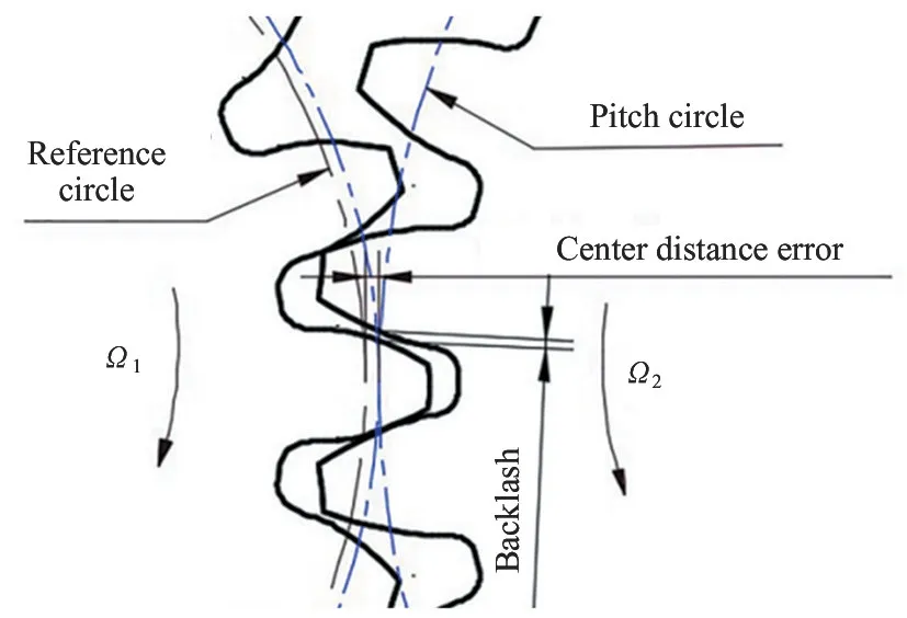
Fig.1 Backlash of spur gear
When the backlashb0is greater than the allowable value,the gear transmission system produces an impact phenomenon,leading to significant vibration,noise,and dynamic load,thus affecting the stability,reliability,and life of the gear transmission system.In this study,the effect of an ISFD on the dynamic characteristics of a spur gear transmission system with a centerdistance error was investigated by building a spur gear test bench.
1.2 ISFD structure design
The ISFD structure is illustrated in Fig.2.To verify the vibration and noise reduction effect of the ISFD,sleeves of the same size were designed for comparison and static analysis.The results of the static analysis are shown in Fig.3.

Fig.2 ISFD structure diagram
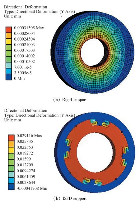
Fig.3 Contours of rigid support and ISFD support
As shown in Fig.3,the deformation of the rigid support is smaller than that of the ISFD support.The stiffness of the ISFD and rigid support are 3.64×10⁷N/m and 7.68×10⁷N/m,respectively.By analyzing the deformation of the ISFD,it is clear that the deformation at the position of the“S-shaped”spring decreases gradually from inside to outside,which shows that the vibration energy from the system can be transferred to the ISFD through deep groove ball bearings.The elastic deformation of the ISFD squeezes the oil film in the clearance of the S-shaped spring,forming dynamic pressure oil film to dissipate the vibration energy,which can reduce the vibration and impact of the gear system,and realize vibration and noise reduction.The damping coefficient of the ISFD can be determined using a mechanical impedance test or computational fluid mechanics(CFD)method[15].Using CFD,the damping coefficient of the ISFD model used in this study is founded to be approximately 1×10⁴N·m/s.
1.3 Model building
When considering the effect of the tooth surface friction,the translational freedom of the spur gear system in the direction perpendicular to the line of action must also be considered.The corresponding system dynamics model is shown in Fig.4[19].

Fig.4 Dynamic model of spur gear system
The system is a two-dimensional plane vibration system with six degrees of freedom,including four translational degrees of freedom and two rotational degrees of freedom.The generalized displacement matrix of the system can be expressed as

Similar to the case without considering tooth surface friction,the dynamic meshing force can be expressed as

The tooth friction force can be approximately expressed as

wherefdenotes the equivalent friction coefficient,andλis the direction coefficient of gear friction,Ffis+1 in the positive direction ofx,otherwise,it is-1.Thus,the analytical model of the system is described as follows.
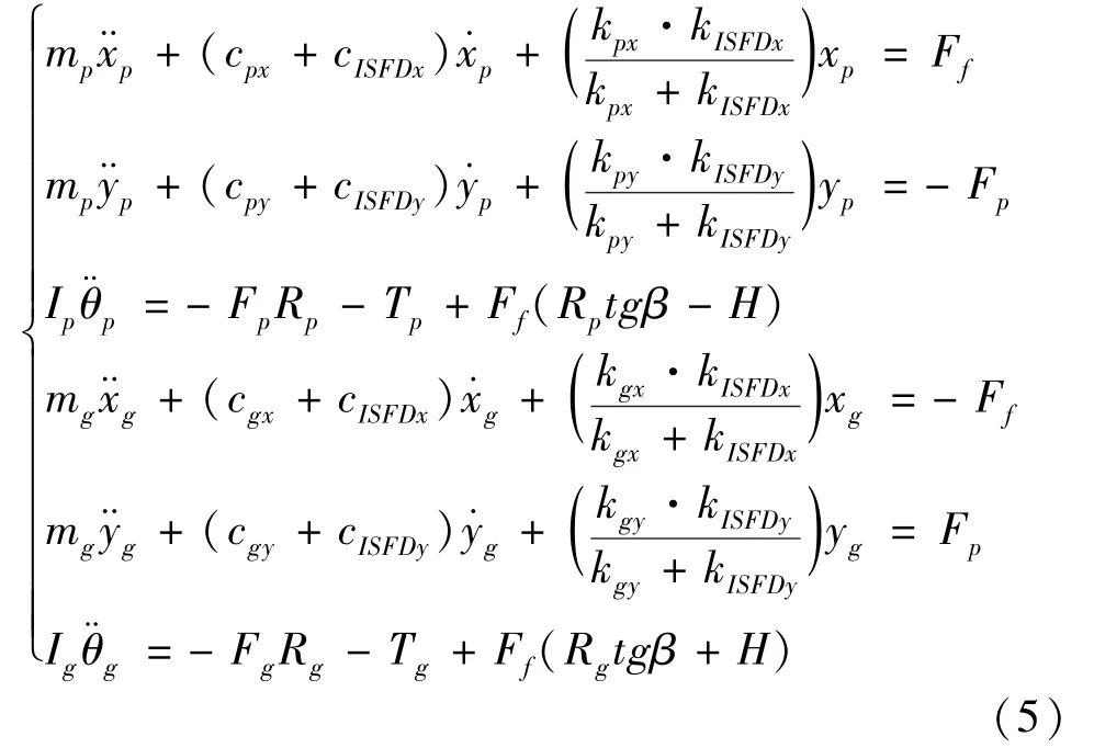
As many results have been derived in detail,they are not repeated here.According to Eq.(5),by increasing the ISFD in the spur gear transmission system,the damping at the support position is increased,and vibration and impact energy caused by the time-varying meshing stiffness and backlash of the spur gear system are dissipated,causing the transmission system operate more smoothly;thus,the accuracy and lifetime can be guaranteed.
2 Spur gear system test bench
2.1 Test bench description
The spur gear system parameters are listed in Table 1.The power plant utilizes 1.5 kW direct current(DC)speed regulating motor with a working speed of 0—10 000 r/min and employs a pulse-width-modulation(PWM)speed regulating device to control its speed.The layout of the spur gear test bench is shown in Fig.5,and the corresponding spur gear test bench is shown in Fig.6.A rigid sleeve was designed for comparison to investigate the damping characteristics of the ISFD,based on the model used in the second part.The structures of the two supports are shown in Fig.7.

Fig.5 Layout diagram of spur gear test bench
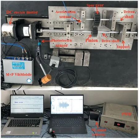
Fig.6 Spur gear system test bench

Fig.7 Comparison of support structure
2.2 Test bench debugging
To ensure the correct meshing of the spur gearpair and the controllability of the experimental variables and reduce the influence of different variables on the experimental results,the rigid support and ISFD should be consistent as far as possible with respect to the installation center distance,circular jump error,and end face jump error.The test bench was debugged using a micrometer and Vernier calipers.The comparison results between the installation center distance and the theoretical center distance of the spur gear pair are shown in Table 2.The center distance was measured at the end of the gear.
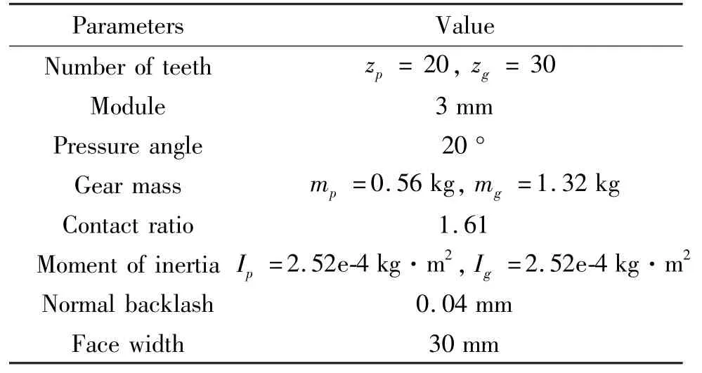
Table 1 Critical parameters of spur gear system

Table 2 Center distance of spur gear pair
3 Results and discussion
After debugging the test bench,the vibration and noise signals of the spur gear transmission system were collected;the measurement points are shown in Fig.8-Fig.13.The acquisition of noise data in a semi-anechoic room ensured the reliability of the test results.The vibration acceleration frequency domain and sound power signals were measured at the rotating speed of 60,300,600,900,1200,and 1500 r/min.The broadband vibration and noise reduction effects of the ISFD were verified.

Fig.8 Rotational speed n=60 r/min test results

Fig.13 Rotational speed n=1500 r/min test results
(1)For working condition 1,the rotating speed is 60 r/min(rotating frequency of 1 Hz,meshing frequency of 20 Hz).
(2)For working condition 2,the rotating speed is 300 r/min(rotating frequency of 5 Hz,meshing frequency of 100 Hz).
(3)For working condition 3,the rotating speed is 600 r/min(rotating frequency of 10 Hz,meshing frequency of 200 Hz).
(4)For working condition 4,the rotating speed is 900 r/min(rotating frequency of 15 Hz,meshing frequency of 300 Hz).
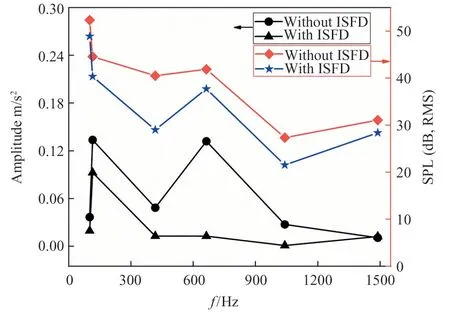
Fig.9 Rotational speed n=300 r/min test results

Fig.10 Rotational speed n=600 r/min test results

Fig.11 Rotational speed n=900 r/min test results
(5)For working condition 5,the rotating speed is 1200 r/min(rotating frequency of 20 Hz,meshing frequency of 400 Hz).
(6)For working condition 6,the rotating speed is 1500 r/min(rotating frequency of 25 Hz,meshing frequency of 500 Hz).

Fig.12 Rotational speed n=1200 r/min test results
According to the rigid support spectra shown in Fig.8-Fig.13,the acceleration amplitude was the highest at frequencies of 120,330,420,650,1050,and 1450 Hz.After the modal analysis of the components of the spur gear transmission system,it was determined that this phenomenon occurred when the impact energy caused by the increase in the tooth gap leads to the resonance of the transmission shaft.In the spectrum diagram,the resonance frequency modulation phenomenon with the rotational frequency and its double frequency corresponds to the modulation frequency.It can also be seen from the spectrum diagram that when the impact energy caused by backlash is small,the ISFD support does not have a significant role in vibration and noise reduction.The reason for this result can be summarized as follows:only when the vibration energy of the system exceeds a certain value can the ISFD play a role in vibration absorption;thus,it does not always affect vibration and noise reduction.With a further increase in rotational speed,the impact energy of the spur gear meshing transmission increases,and the ISFD produces a dynamic pressure oil film effect,which provides damping for the system and effectively dissipates the impact energy of the spur gear transmission system.In addition,by comparing the measured results of vibration and noise with respect to the rigid support and the ISFD elastic damping support at various speeds,it was found that the ISFD can suppress the vibration and noise of the spur gear over a wide frequency band,which is conducive to the smooth operation of the system.
4 Conclusions
The effect of an ISFD on the dynamic performance of a spur gear with a center-distance installation error was experimentally studied by building a test bench for a spur gear transmission system.The following conclusions were drawn.
A spur gear test bench with a center-distance installationerror was built to study the broadband vibration and noise reduction effects of the ISFD.The experimental results indicate that,compared with a rigid support,the ISFD reduces the vibration amplitude of the spur gear system by 40% and the noise by approximately 5 dB.
By analyzing the modal and experimental results of the spur gear transmission system,it is clear that the gap between a pair of gears increases because of the installation error,and the impact energy generated causes resonance of the shaft.Therefore,this study provides a reference for the diagnosis of gear clearance faults in spur gear transmission systems.
The test results indicate that the ISFD can effectively absorb the impact energy caused by the increase in the backlash,which is conducive to the stable operation of the spur gear transmission system.
 High Technology Letters2022年4期
- High Technology Letters的其它文章
- Research on buffer structure and flow field simulation of swash plate plunger type hydraulic transformer①
- Workspace optimization of parallel robot by using multi-objective genetic algorithm①
- Design and implementation of gasifier flame detection system based on SCNN①
- A simplified hardware-friendly contour prediction algorithm in 3D-HEVC and parallelization design①
- An efficient cross-layer buffer management optimization scheme for 5G protocol stack①
- Joint utility optimization algorithm for secure hybrid spectrum sharing①
