Programmable Adaptive Security Scanning for Networked Microgrids
Zimin Jing,Zefn Tng,Peng Zhng,*,Ynyun Qin
a Department of Electrical and Computer Engineering,Stony Brook University,Stony Brook,NY 11794,USA
b Department of Computer Science and Engineering,University of Connecticut,Storrs,CT 06269,USA
ABSTRACT Communication-dependent and software-based distributed energy resources(DERs)are extensively integrated into modern microgrids,providing extensive benefits such as increased distributed controllability,scalability,and observability.However,malicious cyber-attackers can exploit various potential vulnerabilities.In this study,a programmable adaptive security scanning(PASS)approach is presented to protect DER inverters against various power-bot attacks.Specifically,three different types of attacks,namely controller manipulation,replay,and injection attacks,are considered.This approach employs both software-defined networking technique and a novel coordinated detection method capable of enabling programmable and scalable networked microgrids(NMs)in an ultra-resilient,time-saving,and autonomous manner.The coordinated detection method efficiently identifies the location and type of power-bot attacks without disrupting normal NM operations.Extensive simulation results validate the efficacy and practicality of the PASS for securing NMs.
Keywords:Networked microgrids Programmable adaptive security scanning Coordinated detection Software defined networking
1.Introduction
Networked microgrids(NMs)can not only flexibly accommodate distributed energy resources(DERs),but also operate autonomously and cooperatively to overcome possible power deficiencies and prevent power outages[1,2].As a typical cyber–physical system,NMs increasingly rely on computer networking technologies to manage coordinated operations,handle contingencies,and facilitate the implementation of microgrid applications[3].However,this introduces potential vulnerabilities[4].Significant amounts of data,including those measured by sensors monitoring NMs’operational conditions and various control signals applied to accomplish different microgrid applications,need the assurance of confidentiality,integrity,and availability to achieve secure and reliable NM operations[5].In addition,the distributed and plugand-play nature of DERs presents challenges because they are owned and operated by separate microgrid owners,while NM operators have insufficient capability to manage high DER security levels.A series of new technical challenges must be addressed by the NMs to manage these emerging risks,specifically the development of new countermeasures to identify and mitigate threats to microgrid operations on DER-targeted attacks[6],that is,the use of power bots,which are DER devices controlled by remote attackers[1].Therefore,addressing these challenges requires that NM operators implement new approaches to detect cyberattacks on independently owned microgrids.
As fundamental NM components,DERs can not only generate electricity but also serve as sophisticated management tools enabled by multifunctional inverters with wired and/or wireless connections[7].The prevalence of this DER type and the increased deployment of information and operational technologies significantly extend network connectivity,thus expanding the cyberattack surface.To enable a more flexible,reliable,and resilient system,some inverters often integrate cyber elements,including various communication and computing infrastructures[8].However,these will inevitably increase the cyberattack risks on portions of the DER inverter functions,even hijacking the entire DER inverter.Therefore,attackers are not constrained to attacking communication-based microgrid functions or applications.These functions or controls of DER inverters depending less on communication,such as droop control,can also be compromised[9].By compromising the DER inverters,the attacker can severely deteriorate or collapse the microgrids,resulting in a significant loss of power systems.Different attacks have been proposed in recent years,among which the power-bot attack is a critical threat to reliable inverter operations owing to its complexity and drastic destruction[10,11].A single attack scheme,such as simply modifying the parameters of an inverter’s controller,is likely to be detected[1,12].However,these methods fail to work under hybrid cyberattacks.
In practice,attackers are not constrained to follow prescribed schemes.Informed attack schemes combining intrigue,coordinated,and simultaneous attacks can cause more devastating damage[13,14].Attack detection must make use of certain approaches to identify malicious microgrid attacks and then take effective countermeasures to eliminate their adverse effects on stable and reliable microgrid operations.Recent work on joint attack detection primarily focuses on false data injection,deception,and denial of service attacks on advanced metering infrastructure related functions[15],such as load frequency control.These studies apply residue or state estimation approaches,including the use of Kalman filters[16],state forecasting[17],watermarking[10],and data-driven techniques[18,19].Reliance on the system model and parameters is the key shortcoming of model-based algorithms for injection and replay attacks.Even slight uncertainties in these parameters may result in a false detection performance[20].Furthermore,the heavy computational complexity prevents the application and scalability of these algorithms,especially when an iterative process is involved with divergence issues.The selection of a fixed threshold setting may also lead to falsified attack detection performance,especially when the NMs experience dynamic or loading variations.Although the data-driven methods reduce the erroneous detection performance caused by the parameters and modeling uncertainties,the need for extensive training samples along with a time-consuming training process can hardly be suitable for detection of DER-targeted attacks,as these methods may perform well for the selected training cases,but not for all cases,and the inverter controller models and parameters continuously change[21].Therefore,most of these existing models,parameter-,or data-dependent approaches are hardly appropriate for the detection of more sophisticated power-bot attacks targeting DER controllers with improved privacy and varying control strategies in a dynamic networking environment[22].
Meanwhile,employing advanced communication infrastructure and network management techniques provides significant benefits for NMs[1,8].Software defined networking(SDN)is an innovative technique that promotes programmable,scalable,and fastresponding operations in NMs[23].In particular,adopting SDN facilitates the integration of DERs with various communication techniques,direct network programmability,system-wide communication visualization,and enhanced cyber security and system resilience[24].Moreover,SDN has revolutionized the detection and mitigation of cyberattacks on networks by enabling the implementation of different promising defending algorithms[8,25].However,there lacks an SDN-integrated scheme for NMs in the literature that is capable of detecting and mitigating multiple powerbot attacks.
To bridge these gaps,this study focuses on the detection and mitigation of power-bot attacks using informed schemes.Specifically,the three most common attack types,namely controller manipulation(topology modification and parameter overwriting),replay,and injection attacks,are considered.A programmable adaptive security scanning(PASS)architecture was devised.This approach employs both the SDN technique and a novel coordinated detection method capable of enabling programmable,scalable,and ultra-resilient NMs in a simplified,time-saving,and autonomous manner.The coordinated detection method equipped with two devised real-time detectors is designed to identify power-bot attacks without restrictions of attack schemes on DER controllers.The key contributions of this study are as follows:
(1)A novel SDN-enabled PASS architecture is designed for the real-time detection of power-bot attacks on DER inverters with significant flexibility,scalability,and ultra-resilience.
(2)A novel coordinated detection method equipped with two detectors was devised to efficiently detect power-bot attacks.
(3)The PASS detection rules in droop-controlled NMs are derived,and the coordination of dynamic probe signals and detectors to distinguish attack schemes is provided.
(4)Extensive simulation studies were performed to validate the effectiveness and practicality of the PASS for securing NMs.
The remainder of this paper is organized as follows:Section 2 describes the overall PASS architecture.Section 3 presents the coordinated detection method and detection principles of the two detectors.In Section 4,tests are performed to validate the effectiveness and practicality of the proposed PASS approach.Finally,Section 5 concludes the paper.
2.SDN-enabled PASS architecture
The generic PASS framework is illustrated in Fig.1.It consists of three layers:①DERs in physical NMs;②an NM control center(NMCC)and SDN-enabled network layer for monitoring operation conditions,sending critical control signals,and generating programmable probe signals;and ③a power-bot attack detection layer for identifying attacks on the DER inverters via the secured,programmable,and resilient SDN network.The NMCC is responsible for operating and controlling the NMs and coordinating various microgrid applications,including implementing PASS by generating and delivering programmable probe signals.Specifically,the operational status(connected or exited)of all DERs and the inverter controller responses are continuously monitored and transferred back to the NMCC via the SDN network.The NMCC then sends control and probe signals to the DERs for processing NM operations and security scanning.
As shown in Fig.1,a logically centralized SDN controller is the basis for implementing PASS.It provides advanced communication network visibility and management,and detailed visualization of network conditions,including capacity utilization and communication path selection.Its dynamic programmability and direct network control capability adapt to the characteristics of NMs and facilitate the integration of PASS into NMs[1,8,26].Specifically,facilitation is due to the following two aspects:
(1)Resilient communication network.The SDN enables intact on-demand communication paths for control and probe signals by reconfiguring switches,thus establishing alternative routes once either a communication attack occurs or the topology changes owing to microgrid application implementation,such as plug-and-play.
(2)Real-time communication network verification.Both the time-critical characteristics of PASS and normal NM operations rely on an entirely continuously accessible communication network.The network visibility and data flow visualization offered by SDN ensure that packets can be sent to the destination DERs even under undesired conditions such as network malfunctions and congestion by developing a self-healing communication network that exploits the SDN offered features of programmable and dynamic configurations.
The overall PASS procedures are summarized as follows:
(1)Detection rules are created within the NMCC based on the output results of the two coordinated detection method detectors under normal conditions,that is,without attack,as discussed in the next section.
(2)Certain probe signals,that is,sinusoidal waves with low amplitude,are sent by the NMCC to the DER controller via the secured SDN network.Once the signal is received by a DER controller,its response is synchronously sent to the NMCC via the SDN network.
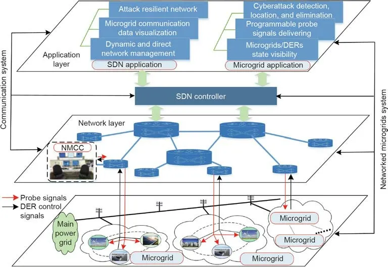
Fig.1.PASS architecture.
(3)The coordinated detection method is performed within the NMCC to calculate the detection results using the information received from each DER.
(4)The calculated detection results are compared with the detection rules.Once a large deviation occurs,an attack is detected.The type of attack can be identified using the two coordinated detection method detectors.
Specifically,the real-time DER state visualization is conducted in the NMCC to determine whether new probe signals should be generated and delivered.When microgrids experience dynamics,which include connection/disconnection of DERs,control strategy variations and changes in the microgrid topology,the detection procedure should be adjusted accordingly before conducting the attack detection procedure.When the DER connection occurs,two additional steps should be performed:①programming of suitable probe signals,and ②configuration of the routing path for probe signals and control signals of DER inverters.In contrast,for the DER disconnection,the NMCC terminates the entire procedure.When a control strategy varies,the detection rules should be re-created according to the new control strategy and the probe signals should be re-programmed.When the microgrid topology changes,the communication network should also be reconfigured to ensure that reliable communication exists between DERs and NMCC before conducting the detection procedure.
Owing to the programmability of SDN,it is possible to vary the scanning frequency and target microgrids,and the PASS can easily be extended by incorporating additional detection methods.
3.Coordinated detection method for DER inverter controllers
A malicious attacker can launch different attacks simultaneously to compromise DERs.In this study,the three most common power-bot attacks,namely controller manipulation(i.e.,topology modification and parameter overwriting),replay,and injection attacks,are investigated in droop-control-based NMs.Specifically,the attacker can modify the topologies and parameters of inverters’controllers and manipulate the data exchanged among different DERs.An illustration of the three power-bot attack types and the established cyber-secured detection method is shown in Fig.2.
To effectively identify the three types of attacks,the devised coordinated detection method utilizes two real-time detectors:a synchronous detector(SD)[11]and a Duffing oscillator detector(DOD)[27].To ensure the real-time power-bot attack detection and normal uninterrupted DER operations,two combined sinusoidal signals with low magnitudes are applied as probe signals with the following two features:①Probe signals pose no impact on the DER inverter performance,and ②probe signals cannot be easily eavesdropped owing to the programmable characteristics.To avoid possible DER disturbances,the probe signals are designed to have three features,which can be mathematically expressed as①s(t)=s(t+NT),whereNis an integer,② ‖s(f)‖≤ε,andwheretrepresents any one particular moment on the whole time axis,Tis the period of continuous signals(t),‖*‖is theL2norm of the harmonic at the frequencyf,and ε is a small threshold.The designed probe signals ensure that their impact on the target DERs within one period is zero;in other words,the probe signals do not change the overall DER controller performance,and thus,the disturbances to the physical systems can also be avoided[1,11].Specifically,the probe signalssd(t)andsq(t)in Fig.2 can be expressed as follows:

where αdjand αqjare the amplitudes(dandqrepresent direct and quadrature axes,respectively),and ωdjand ωqj(j= 1 or 2)are the frequencies of the sinusoidal signals,respectively.sd1(t)andsq1(t)are utilized to detect modification and overwriting attacks via a synchronous detector.sd2(t)andsq2(t)are used to detect replay and injection attacks via a DOD.To ensure that there is no interference,ωd2and ωq2should be integer multiples(≥2)of ωd1and ωq1,respectively.
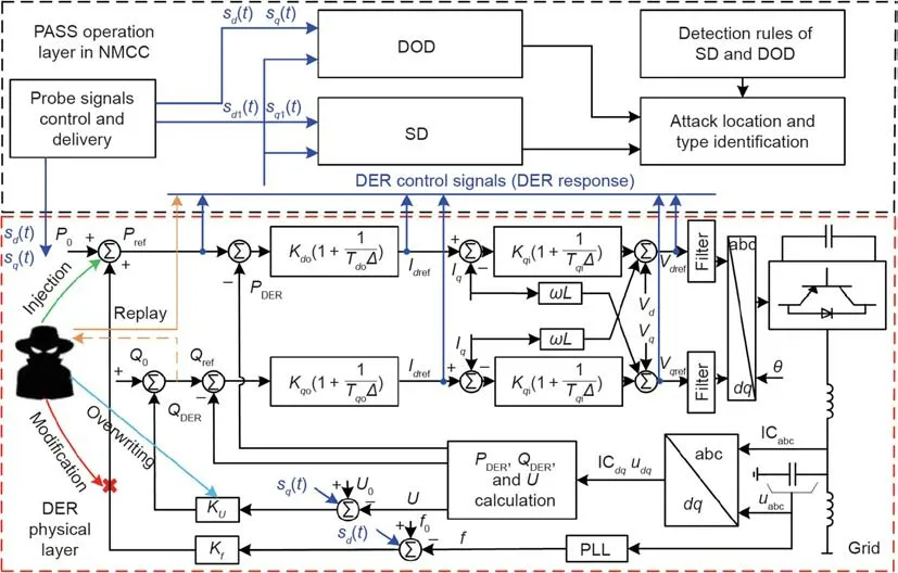
Fig.2.Power-bot attacks on droop-control-based DER inverters.DOD:Duffing oscillator detector;SD:synchronous detector; u:instantaneous voltage;IC:instantaneous current;a,b,and c:three phases;d:direct axis;q:quadrature axis;PLL:phase locked loop;θ:voltage phase;ω:angular frequency;L:inductance;f:grid frequency;f0:initial operating value of frequency; U0:initial operating value of voltage; U:root mean square(rms)of voltage; I:rms of current;Δ:Laplace operator;PWM:pulse width modulation;P:active power;Q:reactive power;P0,Q0:initial active and reactive output power of DER;V:reference voltage;Kdo,Kqo,Kdi,Kqi:parameters of outer and inner loop controllers; KU, Kf: parameters of droop controllers; Tdo, Tqo, Tdi, Tqi:time constants of outer and inner loop controllers;ref:reference.
The coordination of detecting the three types of attacks is based on the following two aspects:① coordination between programmable probe signals and corresponding detectors,and②coordination of the two detectors to identify attack types.It should be noted that the two devised detectors can effectively identify the attack without requiring the system model and parameters,computational complexity,and the burden for data processing,which are discussed in subsequent subsections as follows.
3.1.Synchronous detector and its detection rules
(1)Detector for droop-control-based DERs:Droop control can enable flexible switching between grid-connected and island type operations.The droop coefficients are important in maintaining the rated frequency and voltage.Consequently,attacks on droop controllers are threatening because they can result in immediate deterioration or even collapse of NMs.In this section,the detection of thef–PandU–Qtype of droop controller is presented as an example for creating the detection rules of the synchronous detector.It should be noted that this method works for widely applieddqdouble-loop controllers with different control strategies,and the corresponding detection rules can be derived in a similar manner.This is described as follows.
The synchronous detector works in real time to obtain the detection signals as

wheres(t)refers tosd1(t)orsq1(t);r(t)represents the DER response,that is,Pdref,Qdref,Idref,Iqref,Vdref,orVqref.Dis the detection signal,that is,Df,DU,Ddo,Dqo,Ddi,orDqi.The meaning of the subscripts has been defined in the caption of Fig.2.
(2)Detection rules:Given the topologies and parameters of the DER controllers,the detection signals can be obtained.TakingDdias an example,we can express it as follows:
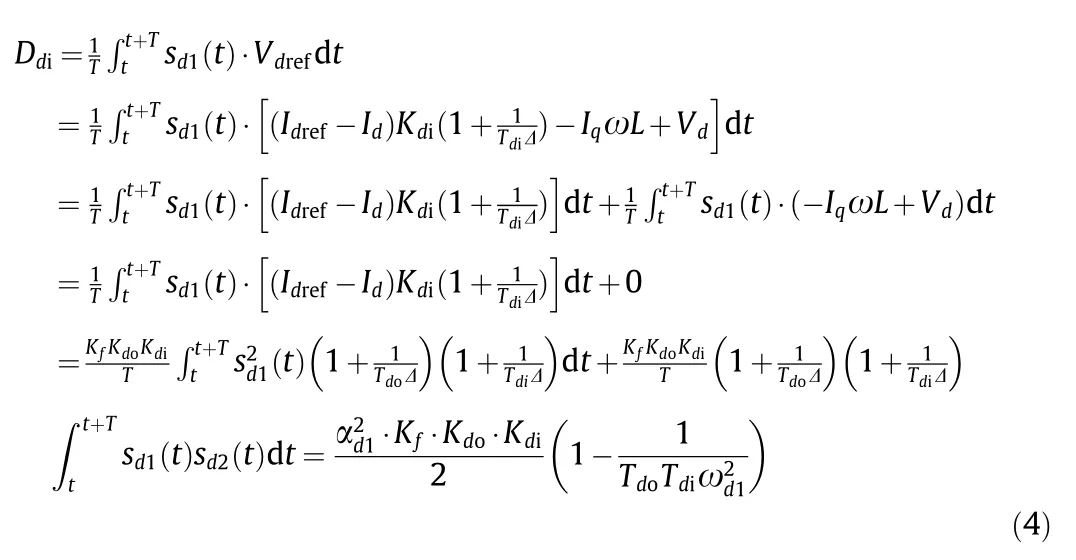

From Eqs.(4)–(9),it can be seen that eachDis determined only by the controller coefficients and the amplitude or frequency of the probe signal.Any attack on the controller that alters the coefficients can result in abnormal detection results.The designed detector in Eq.(3)only requires the controllers’ responses and,hence,will not impact the privacy of DERs.
When all the DER controllers are intact,the detection signal steady-state valuesDf,DU,Ddo,Dqo,Ddi,andDqiare equal to the values calculated in Eqs.(4)–(9),respectively.Once an attack is launched,the calculated values deviate from the established norm.Specifically,the abnormal values under two types of controller manipulation attacks,namely,① topology modification and②controller parameter overwriting/changing,are summarized in Table 1.It should be noted that the values shown in Table 1 are derived under the assumed steady state of specific attacks similar to Eqs.(4)–(9),and these values may not be equal to the detection values in reality owing to caused disturbances.Table 1 clearly shows the corresponding variation in the detection values of the two types of controller manipulation attacks for all possible locations.By detecting abnormal values in comparison to Eqs.(4)–(9)and comparing them with those in Table 1,the two controller manipulation attack types and their locations can be identified.

Table 1 Values of synchronous detector under attacks.
3.2.DOD and its detection rules
Both data sent from the DERs to the NMCC and control signals sent in the reverse direction are likely to be exposed to attackers.In this subsection,we present the second detector,namely the DOD,for detecting the replay and injection attacks coordinated with the SD.Specifically,the attacker can launch replay attacks by first replicating the recorded responses and then sending them to the NMCC repeatedly or with a delay to disable the SD,because the NMCC cannot receive the actual inverter controller responses.The injection attack can be conducted by injecting additive malicious signals either into the DER controllers or directly into the detection layer to disrupt the stable microgrid operation or disable the SD.
The idea of the DOD is to superimpose weak dynamic authentication signals on the DER control signals.The DOD is able to detect weak sinusoidal signals with a very low magnitude and is immune to noise[27–29].In this study,the frequencies and magnitudes ofsd2(t)andsq2(t)can easily be dynamically adjusted to construct the authentication signals,which are then detected by the Duffing oscillator.Any replay of recorded inverters’ responses will alter the predetermined dynamic authentication signals as well as the corresponding DOD operation patterns,and thus will be detected.Conversely,the injection attack has no impact on the DOD operation pattern owing to its selectivity,but can be detected by the SD[27].Therefore,the two types of attacks can be identified by the coordination of the two detectors.
(1)DOD:The normal Duffing equation can be written as follows[29]:

where δ is the damping ratio,the polynomial ‘‘-x+x3” is the nonlinear restoring force,and γcos(t)is either the periodic driving force or the reference signal.If δ is fixed and γ increases,the system state changes from chaotic motion to large periodic motion.When γ reaches the signal magnitude threshold(i.e.,0.82 in this study when δ is 0.5),the system enters the critical state,where the Duffing oscillator becomes very sensitive[28].To obtain γcritical,one can simply increase the driving force amplitude and observe the Duffing oscillator system phase trajectory.Specifically,only when the signal to be detected has the same frequency as the driving force,the Duffing oscillator phase trajectory rapidly enters the periodic state;otherwise,the system is still chaotic.This is the Duffing oscillator selectivity and can be utilized to detect replay attacks as follows.
To detect the authentication probe signal,the Duffing oscillator must inject an input signal(reference signal).The probe signal to be detected can be regarded as a reference signal perturbation.The frequencies and magnitudes of these two signals are dynamically coordinated within the NMCC.According to the DOD phase trajectory change DOD,the detected signal,whether or not it contains the probe signals sent from the NMCC,can be determined.Note that the Duffing oscillator is immune to noise because it only affects the local trajectory with no state transition.
To use Eq.(10)to detect signals with different frequencies,a frequency transformation should be performed.DefiningEq.(10)can be rewritten as

Lett=ωτ(τ is an intermediate variable for transformation).The following equations hold:

Substituting Eqs.(13)–(15)into Eqs.(11)and(12),and omitting the intermediate variablex*subscript,the equations suitable for different frequencies are as follows:

where Δγtis the input signal,including the probe signal and noise.Because Eqs.(16)and(17)are derived from Eq.(10),the system properties and critical values are not altered.Thus,after filtering the direct current(DC)component,the DER control signals can be injected into Eqs.(16)and(17)to detect replay attacks.
To demonstrate the working principle,the two states of the Duffing oscillator are illustrated in Fig.3,where the sum of the distanceslfrom the moving point in the locus to(-1,0)and(1,0)is used to facilitate fast automatic state identification.Comparinglunder the two states,it can be noted thatlis always greater than three under the large periodic state,whilelis between two and four under the chaotic state.Therefore,a threshold,l= 2.5,was used in this study to identify the states,as indicated by the red dashed line in Fig.3.Oncelis less than 2.5,it can be confirmed that the Duffing oscillator is in a chaotic state;otherwise,the Duffing oscillator is in a large periodic state.
(2)Detection rules:The Duffing oscillator reference signal is set such that it operates in chaotic motion.Specifically,the amplitudes of probe signalssd2(t)andsq2(t)coordinated with the reference signals are programmed to change every 0.05 or 0.1 s to make the oscillator operate alternatively between the two motion states,as shown in Fig.4.Because the frequencies are no larger than 0.1 s,the signals injected into the Duffing detector by replay and injection attackers are different from those generated in the NMCC.Thus,the operational state pre-defined by the NMCC will be broken owing to its sensitivity and selectivity,and replay and injection attacks will be detected.
3.3.Detection rules for attack types and locations
The NMCC delivers programmable probe signals to DERs.Coordinated with the above two detectors,the attack types can be determined based on the detection rules of the coordinated detection method given in Algorithm 1.The attack locations can be identified based on the detection results with abnormal values.In particular,the detection rules for simultaneous injection and overwriting attacks are slightly different based on different injection signal types.If the injected signals are DC components,the simultaneous attacks cannot be identified with Algorithm 1,because the detection results are the same as those under only the overwriting attack.Considering that the injected signals can be seen as corresponding references to each loop and the NMCC continuously monitors each loop’s control signals,which are also each loop’s responses,the NMCC can easily identify the simultaneous attacks by comparing the responses of each loop with those under normal controls.If the controller response is normal,while the synchronous detector detection result deviates from the normal values,it means that only an overwriting attack is occurring.If the controller response is abnormal,while the detection values are normal,then only an injection attack is occurring.If both the controller response and detection values are abnormal,then injection and overwriting attacks are occurring.If the injected signals are not DC components,the attack type can be identified using either the method for DC component injection attack or Algorithm 1 because the detection results are different from those only under an overwriting attack.

Fig.3.Two Duffing oscillator states:(a)periodic motion and(b)chaotic motion. x:variable of the Duffing oscillator equation; x′:derivative of x.

Fig.4.Duffing oscillator for attack detection.(a)Alternating motion state of DOD;(b)large periodic motion state of DOD.

Algorithm 1.Detection rules for attack types.for all values of Df, DU, Ddo, Dqo, Ddi, Dqi do if there exists 0 then Topologies modification attack detected;else if Df, DU, Ddo, Dqo, Ddi, Dqi are normal then if Duffing detectors results are normal then There are no attacks.else Replay attacks detected.end else if Df, DU, Ddo, Dqo, Ddi, Dqi are normal then Injection attacks detected.else Parameters overwriting attacks detected.end end end end
4.Test and validation
The effectiveness and practicality of PASS in detecting powerbot attacks were tested and validated with a typical NM system,as shown in Fig.5.The test system consisted of six microgrids and operated in the island mode.The NMs were modeled in MATLAB/Simulink,and the simulation time step was 50 μs.The probe signals are programmed within the NMCC and delivered to the destination DERs through SDN simulated in Mininet[30].Specifically,the effectiveness of the two detectors under each single attack is validated in Sections 4.1 and 4.2.Then,the performance of the two detectors under complex attacks are evaluated in Section 4.3.Finally,the effectiveness of the proposed coordinated detection method is verified in Section 4.4.
To illustrate the proposed SDN-enabled implementation method,we provide the details of the testing environment setup,network connection,and system operation process.The PASS testing environment consists of a microgrid simulator,an SDN simulator,and an NMCC.The network connection of the three components and a flow chart for the implementation of the coordinated detection method running in the NMCC are shown in Fig.6.
This NM test system includes six microgrids,operates in the island mode,and is developed and compiled in MATLAB/Simulink.More test system details are presented in Fig.6.The built-in Simulink sender and receiver modules were used for communication.The internet protocol(IP)addresses of the six microgrids are set from 10.0.0.1 to 10.0.0.6.The DER inverter control signal measurements are transmitted through the SDN and sent to the NMCC,whose IP address is 10.0.0.7.The NMCC runs on a remote server,which can receive the DER operational status(connected or disconnected)and the inverter control signals and sends the programmable probe signals back to MATLAB/Simulink,to perform PASS with the implementation of the coordinated detection method,programming,and delivering probe signals.After being connected to the simulator,the server enters the listening mode and receives packets whose destination IP and port match those of the server,and then performs the PASS.The middle of Fig.6 shows the SDN topology used for the networked microgrid system,which includes five switches and one SDN OpenFlow controller Ryu[30].The SDN network runs in a Mininet environment.In Mininet,the bandwidth for each link is set to one gillion bits per second(Gbps),which is a common practice applied in the Ethernet network.The user datagram protocol(UDP)[31]is used to transmit data packets between NMs and the NMCC through Mininet[32].
4.1.Verification of synchronous detector for modification and overwriting attacks
(1)Modification attack:In this test case,a modification attack occurs on the inverter’s outer loop power controller of Battery 31 in Microgrid 4 at 1.10 s(Fig.5).Two subcases are performed to demonstrate the testing system performance with and without the synchronous detector.When the detector is activated,αd1= αq1= 0.06,and ωd= ωq= 1256 rad·s-1(1 rad = 180°/π).Fig.7 illustrates the current responses(three phases:a,b,and c)at Buses 20 and 31 and the output power of the droop-controlled DERs when the synchronous detector is disabled.Fig.8 shows the three-phase current and power responses under protection.The changes inDdoin Battery 31 are shown in Fig.9.
From Figs.6–8,the modification attack is identified by the synchronous detector att= 1.11 s whenDdoreaches zero,and circuit breaker(CB)7 is immediately opened to disconnect Microgrid 4 and isolate the attack.
(2)Overwriting attack:In this test case,an overwriting attack is launched on the droop controller of Fuel cell 13 in Microgrid 1 att=1.10 s(Fig.5).The testing system operation was also provided to validate the SD efficacy.The current responses at Buses 13 and 27 and the output power of the droop-controlled DERs are presented in Fig.10 without SD.When SD is put into use,the current response at Bus 27 and the output power of the droop-controlled DERs are shown in Fig.11.The attack is identified att=1.12 s andDdodeviates from the normal value significantly,as shown in Fig.12.
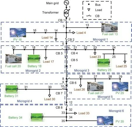
Fig.5.Networked microgrids for validation of coordinated detection.CB:circuit breaker;PV:photo voltaic;1–35 are bus numbers.

Fig.6.Network connection of the PASS simulation system.M1–M6 are six microgrids;S1–S5 are five switches;IP:internet protocol.
From Figs.7–12,it can be observed that the impacts of modification and overwriting attacks rapidly spread across the NMs without SD,and NM performance is severely deteriorated(Figs.7 and 10).With SD,the attacks can be identified and their NM impacts can also be mitigated,as illustrated in Figs.8 and 11,which verifies the SD effectiveness in defending against power-bot attacks.
The actualDdovalues before the attacks were close to the values calculated according to the detection function.As shown in Figs.9 and 12,theDdovalues are 3.63 and 1.44,respectively,under the two cases,which are in close proximity to the calculated values,that is,3.60 and 1.44,respectively.TheDdovalues change continuously after Microgrid 4 is disconnected.The values violate the detection values shown in Table 1.This is because the disconnected microgrid operates abnormally,whereas Table 1 provides the steady-state of the detection rules.In practice,attack alarms should be raised once the detection results deviate from normal values to a certain extent,that is,greater than 1.5 or less than 0.5 times the normal operational state values.To protect more critical DERs,narrower thresholds can be set for raising alarms.

Fig.7.(a,b)Current response of Buses 20 and 31 and(c)DER power response under modification without SD.

Fig.8.(a)Current response of Bus 20 and(b)DER output power response with SD.

Fig.9.Detection function value of Ddo in Battery 31.
4.2.Validation of DOD for replay attack
(1)Replay attack:In this test case,a replay attack is launched on the inner loop controller of Battery 34 in Microgrid 6 by injecting the recorded normal operation data.When the DOD is activated,αd2= αq2= 0.01 and the DOD state is programmed to alter the frequency every 0.1 s in the NMCC.The frequency of the recorded signal does not match the dynamically changed signal generated in the NMCC.Thus,the DOD motion state variation takes place upon the occurrence of a replay attack.As shown in Fig.13,the replay attack is launched att= 0.9 s and detected att= 0.94 s.

Fig.10.(a,b)Current responses of Buses 13 and 27 and(c)DER power response without SD.

Fig.11.(a)Current response of Bus 27 and(b)DER output power response with SD.

Fig.12.Detection function value of Ddo in Fuel cell 13.

Fig.13.Detection of replay attack.(a)Motion state of DOD without replay attack;(b)motion state of DOD under replay attack.
(2)Robustness verification:In practice,DOD should be reliable and robust to be applicable,which means:①The sinusoidal signals αd2and αq2should not impact NM normal operations,because the signal amplitude is lower than that of the SD probe signal,the impact can be ignored;and ②the DOD should guarantee the correct detection of weak signals with intense noise.The lowest sinusoidal signal amplitude that can be identified by the Duffing oscillator is 0.0001,and the lowest reachable signal-to-noise ratio(SNR)is-51 dB,as reported in Ref.[27].To demonstrate the competence of the DOD in detecting weak signals with low SNRs,the simulation results are illustrated in Fig.14.
4.3.Incompetence of single detector for attack detection
(1)Malfunction of SD:An additional signal with the same and differentsd1(t)frequencies is injected into the controllers of Batteries 31 and 18 att=1.10 s,respectively(Fig.5).The changes inDdoduring the process are illustrated in Fig.15,respectively.As shown in Fig.15,Microgrids 2 and 4 are disconnected because of the significantDdodeviation.In fact,the inverter controller parameters are not attacked.Thus,SD cannot accurately identify the attack type under an injection attack,although it can isolate the attack.
However,under replay and overwriting attacks,the SD is unable to detect them.Before the overwriting attack is launched att= 1.10 s,the actual control signals are replaced with the prerecorded signals and reported to the NMCC.Fig.16 shows the output power of the droop-controlled DERs and the change inDdoin Battery 31.The NM performance deteriorates severely and eventually crashes.However,the SD cannot identify and mitigate attacks in a timely manner.
(2)Malfunction of DOD:As introduced in Section 3.2,the DOD itself cannot determine the injection attack because of its selectivity.The motion state does not change,as shown in Fig.17(a),when Fuel cell 13 is compromised.Thus,this attack could not be identified.
4.4.Verification of coordinated detection method
(1)Detection of overwriting and injection:When only the injection attack occurs in Fuel cell 13,the change ofDdoand the state of DOD are shown in Fig.17(b).It can be seen that,Ddochanges when the injection attack is launched,while the motion state of DOD and the NMs remain normal operations.Although the SD is misled by the injection attack,the attack’s type can also be identified accurately.
When overwriting and injection attacks occur simultaneously in Battery 18 not only will theDdodeviate from the normal value,but the motion state will also be altered,as illustrated in Fig.18.In comparison with Fig.15(b),the overwriting and injection attacks can be accurately distinguished with the cooperation of the two detectors.
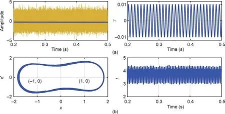
Fig.14.Detection of weak signal with low SNR.(a)Weak signal with intense noise;(b)motion state of DOD with noise.

Fig.15.(a)Change of Ddo in Battery 31 and(b)change of Ddo in Battery 18 under injection attack.

Fig.16.(a)DER power response and(b) Ddo of Battery 31 under two attacks with only SD.

Fig.17.Detection results of(a)DOD and(b)SD in Fuel cell 13.
(2)Detection of modification and replay attacks:A replay attack is launched in Battery 31 by recording the normal operation data and injecting them att= 1.00 s to the NMCC.Meanwhile,a modification attack is launched att= 1.10 s.TheDdoof Battery 31 and the DER output power without the coordinated detection method are shown in Fig.16.When the coordinated detection is activated,the DOD motion states before and after the attack,and the DER output power are shown in Fig.19.
As shown in Figs.16 and 19,the modification attack was undetectable becauseDdoscarcely changed during the joint attack.Consequently,the microgrid cannot be segregated in a timely manner to isolate the attack.When the coordinated detection method is applied,the motion state of the Duffing oscillator changes once the replay attack is launched,as shown in Figs.19(a)and(b).The attack can be detected using the coordinated detection method,and the types are identified.Its impact can also be mitigated to ensure stable NM operation,which validates the effectiveness of the established method.
From the simulations above,when a single detector is activated,the complex malicious attacks can not only mistakenly report attack types but also become undetectable.The devised coordinated detection method is capable of identifying attacks regardless of the attack strategies employed by malicious attackers.The coordinated probe signals are programmed in the NMCC with the SDNbased PASS strategy,which is practically implementable and reliable for NM protection.

Fig.18.Validation of coordinated detection under overwriting and injection attacks.(a)The motion state of Duffing oscillator under attack;(b)power response of DERs.

Fig.19.Validation of coordinated detection under modification and replay attacks.(a,b)The motion state of Duffing oscillator under normal condition and under attack,respectively;(c)the power response of DERs.
5.Conclusions
In this study,an SDN-enabled PASS approach is presented to identify and mitigate complex cyberattacks in NMs.Probe signals are programmed in the NMCC and forwarded to the DER controllers to detect sophisticated attacks,including modification,overwriting,injection,and replay attacks,regardless of the attack templates employed by malicious attackers.By devising a coordinated detection method,the types and attack locations can be detected.The designed programmable strategy can be efficiently implemented to enable microgrid plug-and-play functions.The efficacy and reliability of the proposed method were validated through extensive tests.
Acknowledgements
This work was supported in part by the National Science Foundation,USA(ECCS-2018492,CNS-2006828,ECCS-2002897,and OIA-2040599).
Compliance with ethics guidelines
Zimin Jiang,Zefan Tang,Peng Zhang,and Yanyuan Qin declare that they have no conflict of interest or financial conflicts to disclose.
- Engineering的其它文章
- Selective Laser Melting under Variable Ambient Pressure:A Mesoscopic Model and Transport Phenomena
- Flexibility Prediction of Aggregated Electric Vehicles and Domestic Hot Water Systems in Smart Grids
- An Overview of Metal–Organic Frameworks for Green Chemical Engineering
- Atomic Force Microscopy Measurement in the Lignosulfonate/Inorganic Silica System:From Dispersion Mechanism Study to Product Design
- Engineered Biomimetic Platelet Membrane-Coated Nanoparticles Block Staphylococcus aureus Cytotoxicity and Protect Against Lethal Systemic Infection
- Advances and Strategies for Controlling the Quality and Safety of Postharvest Fruit

