One-pot modified“grafting-welding”preparation of graphene/polyimide carbon films for superior thermal management
LI Hao-liang,WU Xian,CHENG Kui,ZHU Mo-han,WANG Liu-si,YU Hong-liu,YANG Jun-he,3,*
(1.School of Materials Science and Engineering, University of Shanghai for Science and Technology, Shanghai 200093, China;2.School of Medical Instrument and Food Engineering, University of Shanghai for Science and Technology, Shanghai 200093, China;3.Prytula Igor Collaborate Innovation Center for Diamond, Shanghai Jian Qiao University, Shanghai 201306, China)
Abstract:Thermal management has attracted much recent attention due to the rapid development of 5G communication and electronic devices.Reduced GO/polyimide carbon (rGO/PI-carbon) films were prepared by a one-pot“grafting-welding”strategy,where GO was first grafted with amino groups using 1,3-bis(4-aminophenoxy) benzene,then polymerized with polyamic acid (PAA)and pyromellitic dianhydride to connect the GO sheets,before carbonization and graphitization.The rGO/PI film with a mass ratio of GO to PAA of 7% exhibits an increase in in-plane thermal conductivity (1 102 W(m·K)−1) of 48.92% compared with the rGO film.It also has a superior bending performance and survives 2 000 bend cycles with a small radius test while suffering an electrical resistance increase of less than 10%.Grafting-welding of rGO with PI carbon produces effective paths for phonon transport between the graphene sheets,reducing phonon scattering,which makes it a candidate for thermal interface materials for heat dissipation.
Key words:Modification of GO;In-situ polymerization;Polyimide;Graphene composite film;Thermal dissipating performance
1 Introduction
With the rapid development of electronic devices,especially for the widespread application of 5G communication in near future,thermal management has become a critical issue to guarantee the working efficiency and long-term reliability of mobiles[1,2].But the commercially used highly-oriented pyrolytic graphite (HOPG) films,prepared from the polyimide (PI) with graphitization treatment can hardly meet the criteria in heat dissipation performance as well as flexibility[3,4].Thus,it is of great importance in developing an innovative thermal conducting materials (TCMs) for the next generation electronic devices.
Among all of the TCMs,graphene has been regarded as one of the ideal substitutes due to its harmonic sp2hybrid carbon honeycomb lattice structure which endows it with an extremely high thermal conductivity (κ,~5 300 W m−1K−1)[5],far more exceeding than that of bulk graphite limit (~2 000 W m−1K−1),crystalline diamond (~2 300 W m−1K−1) or singlewalled CNTs (~3 500 W m−1K−1)[6].So far,great efforts about the assembly method of high performance graphene films (averageκaround 1 200 W m−1K−1)have been made such as vacuum filtration[7],spray deposition[8],or bar coating[9]and so on.For instance,Shen et al.proposed a mild evaporation method to deliver an ultrathin graphene film with theκvalue~1 100 W m−1K−1[10].More recently,Ruoff’s group proposed a CVD growth method to prepare graphene film with superiorκover 2 292 W m−1K−1[11],but the atomic graphene layer could not be directly used as heat dissipator.As a substitute for graphene oxide (GO),the ball-milling exfoliated graphene was vacuum filtrated and treated at 2 850 °C,and theκvalue even reached 1 500 W m−1K−1due to the avoidance of oxidization of sp2lattice[12].In spite of the considerableκsuperior to commercial graphite film,the value is still much lower than the intrinsicκof graphene because the sheet size and the crystalline structure of graphene is inevitably broken via the harsh chemical or mechanical exfoliation.
In fact,the lateral size and grain domain of graphene or GO is a critical factor to determine theκvalue of graphene based thermal conducting film,as confirmed by both experimental and theoretical researches[13–15].In this regard,rGO with large sheet size collected by centrifugation exhibits significant advantages in thermal performances.Theκvalue of L-rGO(rGO film with large lateral size) is~1 390 W m−1K−1,which is 1.5 times higher than that of S-rGO film[14].The theoretical prediction by molecular dynamic simulation also suggests that theκvalue of graphene sheet is positively related with its lateral size[15].The presence of large amounts of boundaries and lattice defects in the graphene sheets will lead to severe phonon scattering[2,16].Recently,a debris-free GO film prepared by centrifugal collection also displays a superiorκ(~1 900 W m−1K−1) after the graphitization treatment[17].
On the other hand,the functionalization of GO has been also widely developed in improving the processability in various organic solvents or polymer matrixs.The large amount of functional groups such as hydroxyl,carboxyl or epoxy groups etc.in GO can be applied for covalent grafting reaction by isocyanate[18],epoxy ring-opening,carboxylic acylation,and addition[19].For instance,Song et al.introduced ethylenediamine (EDA) grafting onto GO nanosheets via the reaction between amine and carboxyl groups to deliver an ionic sieving composite film[20].Phenylethynyl (PE) was applied for chemical modification to deliver a graphene/PE composite film with superior electrical conductivity[21].The modification of GO offered sufficient active sites to achieve an interaction between graphene polymer matrix so that it showed great potential to deliver graphene based composite material for application.
Herein,we have proposed a one-pot“graftingwelding”method to construct a modified graphene/polyimide (g-A-mGO/PI) composite film to improve theκvalue as well as the flexibility by achieving the covalent connection of GO sheets.GO is firstly modified by 1,3-Bis (4-aminophenoxy) benzene (APB-134),one of the ingredients to synthesis PI,via a microwave-assisted“grafting-to”strategy.Then,the insitu polymerization of polyamic acid (PAA) is further induced at the terminal amino groups to weld of GO sheets into larger ones.The optimized g-A-mGO/PI exhibits aκvalue of 1 102 ± 21 W m−1K−1as well as superior flexibility compared to that of the pristine g-GO film.Such a modified“grafting-welding”strategy contributing to the enhancement in heat dissipation performance shows an efficient and promising way for graphene application for thermal management.
2 Materials and methods
2.1 Preparation of GO and its modification
At first,the graphite powder (5.0 g) was treated in concentrated 50 mL nitric acid (HNO3,69.8 wt%)and 150 mL sulfuric acid (H2SO4,98 wt%).Then the intercalated graphite was thermal-treated at 1 050 °C for 10 s to obtain expanded graphite.Finally,GO was prepared by a modified Hummers method without ultrasonication to prevent the breakage of GO sheets.
In a typical modification process,GO (3 mg mL−1)was firstly dispersed in 20 mL N,N-Dimethylformamide (DMF) uniformly.Then 1,4-Bis(4-aminophenoxy) benzene (APB-134,5 mg) was added into GO dispersion.The mixture was set into a microwave reactor (CEM,Discover SP) and treated at 60 °C for 15 min with an output power of 300 W.The as-obtained product was denominated as APB-modified GO(A-mGO).
2.2 In-situ preparation of A-mGO/PAA and g-AmGO/PI composite films
The A-mGO/PAA-7% was in-situ synthesized by mixing A-mGO and pyromellitic dianhydride (PMDA).Firstly,2.79 mg PMDA was directly added into the as-obtained A-mGO solution under stirring for 2 h at room temperature.As illustrated in Fig.1,the composite film was prepared via a self-assembly method.The A-mGO/PAA solution was transferred into a Teflon plate and heated at 60 °C for 6 h.The as-obtained brown film was denominated as A-mGO/PAA–x%,wherexwas the weight percentage of the PAA to mGO.In this work,xwas set to 1%,4%,7%and 10%,respectively.Then,the films were heated to 350 °C at a rate of 2 °C min−1for 1 h,and then to 800 °C at a rate of 5 °C min−1for further reduction in a hot-pressing furnace under N2protection.Finally,the reduced films were graphitized at 2 800 °C for 45 min under argon atmosphere and denominated as g-A-mGO/PI-x%.

Fig.1 The schematic illustration of g-A-mGO/PI films.
2.3 Characterizations
The Fourier transform infrared spectra (FTIR,P.E.Spectrum 100) was tested by mixing samples with potassium bromide (KBr) under pressure of 15 MPa.The surface and cross-section morphology was observed by scanning electron microscopy (SEM,FEI Quanta FEG,USA) at an accelerating voltage of 30 kV.The energy dispersive spectrometer (EDS,JEOL-2010) was conducted to confirm the distribution of PAA in the composite film.The X-ray diffraction (XRD,Bruker D8 ADVANCE) patterns were measured with CuKα radiation (λ=0.154 nm) at a generator voltage of 40 kV and a current of 40 mA.The Raman spectroscopy (Horiba,LabRAM HR Evolution,France) was employed to analyse the defects and the lateral size of the composite film with a laser of 532 nm.The X-ray photo-electron spectroscopy (XPS,Physical Electronics PHI-5300 spectrometer) was performed using a with a monochromatic MgKα radiation at a power of 250 W and a voltage of 14 kV.The in-plane thermal diffusivity (α) was measured using a laser flash analyzer (LFA 467/Ins Nanoflash,Netzsch).The thermal conductivity (κ) was calculated by the Eq.(1):

whereCpandρrepresent the specific heat and bulk density of the film sample,respectively.The bulk density is calculated from the mass,diameter and thickness of film sample.
3 Results and discussion
3.1 The modification of GO and its characterizations
GO was prepared by a modified Hummers method[22]without ultrasonication as mentioned in our previous work.The average lateral size of GO is~ 30 μm × 30 μm[23].Such an ultrasonication-free method can remain GO sheets with large lateral size as much as possible.The preparation of g-A-mGO/PI film,as illustrated in Fig.1,is described in three steps.Firstly,the mixture of APB-134 (orange dots) and GO dispersion is rapidly heated by the microwave reactor to obtain a uniform temperature field.APB-134 is partially grafted onto GO sheets (A-mGO,GO sheets with red dots) via covalent bonding.The excessive reagent is not removed because it can be utilized in the further in-situ polymerization process.After the graphitization and a roll-to-roll compression treatment,the color of g-A-mGO/PI film exhibits a shiny metallic luster from a dark black color of the mGO solution or the A-mGO/PAA film.
Both the digital photos of GO and A-mGO display an excellent dispersibility in DMF as shown in Fig.S1a.After the microwave-assisted modification treatment,the color of A-mGO turns into dark black from a brown GO solution,indicating APB-134 has grafted onto the GO sheets.Notably,when the temperature reaches over 70 °C,the GO sheets tend to form flocks suggesting the over reaction of GO.Moreover,the FTIR spectroscopy of GO,APB-134 and A-mGO is displayed in Fig.S1b.An additional peak at 1 500 cm−1is observed,corresponding to N―H bending of primary amine groups[24],indicating that APB-134 has successfully grafted onto the GO sheets during the microwave treatment.The thermogravimetric analysis shown in Fig.S1c also demonstrates that the thermal stability of A-mGO is higher than that of pristine GO,due to the partial reduction of GO by the amino in APB-134[25,26].
3.2 Morphology and characterizations
As shown in Fig.2a and b,the representative scanning electron microscopy (SEM) images of the pristine GO film reveal a rough surface with wrinkles.After the modification by APB-134,the surface of AmGO film shows a higher integrity than that of GO,but still with some ripples on the surface.Both the cross-section of GO and A-mGO films displays cracks and holes between the GO layers.But the cross-section of A-mGO/PAA-7% film is more compact than that of GO and A-mGO film.The gaps between GO or A-mGO layers are welded by the presence of PAA resulting in an oriented structure.The thickness of GO,A-mGO and A-mGO/PAA film could be tuned at around 6 μm by controlling the mass of A-mGO.Such a compact structure achieved by“grafting-welding”method can minimize the phonon-interface scattering,thereby improving the heat spreading and mechanical performance[27,28].

Fig.2 The surface and cross-section SEM images:(a,b) GO.(c,d) A-mGO and (e,f) A-mGO/PAA-7%.
Moreover,the cross-section morphology of AmGO/PAA-x% film is shown in Fig.S2 (a-d) (Supporting Information),respectively.With the increasing loading of PAA,A-mGO/PAA-4% and AmGO/PAA-7% display gradually compacted structure,but that of A-mGO/PAA-10% shows a higher extent of disordered structure with cracks or agglomeration ascribed to the excessive PAA.Furthermore,according to the EDS mapping of A-mGO/PAA-7%film in Fig.S2 (e-l),the C,N and O elements are distributed uniformly not only on the surface but also on the cross section of the sample suggesting the the covalent connection of mGO sheets is successfully achieved via the“grafting-welding”process.
The XRD patterns of the as-obtained GO,AmGO and A-mGO/PAA films are illustrated in Fig.3a.The diffraction peak of the GO film is centered at 9.89°,corresponding to an interlayer dspacing of 0.893 3 nm.After the modification by APB-134,the peak position shifts to 9.71° (0.909 8 nm).Such a slight increase ind(001)space of A-mGO could be attributed to the grafting of APB-134 onto the GO sheets[28,29].The characteristic peak has been gradually shifted to 9.11° for A-mGO/PAA-7% corresponding to the largest layer distance of 0.969 5 nm,suggesting the successful intercalation into the mGO sheets by the in-situ synthesis of PAA.After the graphitization treatment,all samples exhibit narrow and sharp peak at~26°,indicating a higher crystallinity (Fig.3b).As concluded in Table S1,the peak positions of g-GO and g-A-mGO are 26.47° and 26.40°,corresponding to ad(002)spacing of 0.336 3 nm and 0.337 2 nm,respectively.While the peak of g-AmGO/PI-7% is centered at 26.50°,corresponding to ad(002)of 0.335 9 nm which is closest to that of the graphite crystal (0.335 4 nm).Moreover,the graphitization degree of the composite film can be determined by the following Eq.(2).
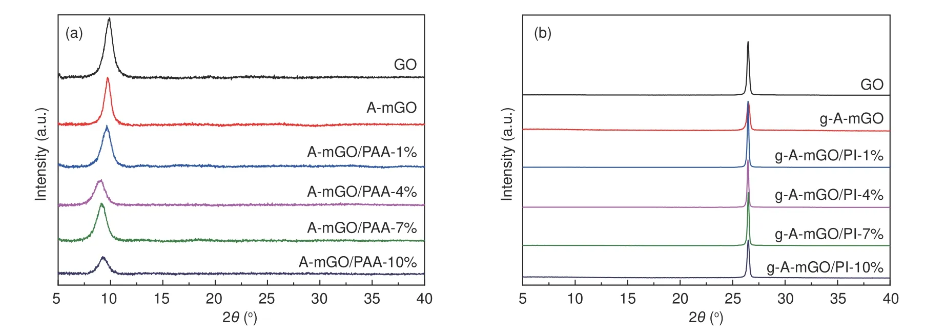
Fig.3 The XRD patterns of A-mGO/PAA films (a) before and (b) after the graphitization treatment.

The value of the g-A-mGO/PI-7% film reaches 94.19%,which is the highest among all samples,indicating a higher restoration degree of A-mGO sheets because of the modification of APB-134 as well as the presence of PI during the graphitization treatment.But the peak position of (002) of g-A-mGO/PI-10% shows an obvious shift to 0.336 8 nm,which can be ascribed to the excessive PI agglomerated as turbostatic structure after the graphitization treatment.
To evaluated the process of in-situ polymerization of PAA,the FTIR spectroscopy of A-mGO/PAA composite film is performed,as shown in Fig.S3.The characteristic bands of A-mGO at 1 706 cm−1and 1 600 cm−1could be attributed to the stretching vibration of C=O and C=C bonding[30],respectively.The peaks located in the range of 3 000-3 300 cm−1could be assigned to the N―H stretches indicating the amino group is attached onto the GO sheets.After the in-situ polymerization,additional absorption peaks at 1 501 cm−1and 1 463 cm−1are assigned to the“ringbreathing”vibration of aromatic amine originated from the amide II stretching vibration[24,31].After the imidization treatment at 250 °C,the peak at~1 558 cm−1corresponding to the C-N-C bonding indicates that the PAA has turned into PI and achieves the connection of A-mGO sheets via covalent bonding[21].
Furthermore,to confirm the interaction between A-mGO and PAA,the X-ray photoelectron spectroscopy (XPS) is further characterized as shown in Fig.4.The C 1s spectra of A-mGO film (Fig.4a) can be deconvoluted into four components arising from C=C/C―C (~284.5 eV),C―N (285.4 eV),C―O―C (~286.7 eV) and O―C=O (~288.6 eV)[32,33].The peak area,as concluded in the inset table,is 42.18%,13.04%,38.61% and 6.17%,respectively.After the imidizaiton treatment at 250 °C (the sample named as A-mGO/PI),as illustrated in Fig.4b,the peak area of C―N bonding has a dramatic increase to 39.71% (vs.13.04%),while the peak area of the C―O―C and O―C=O bonds decreases to 2.07%and 2.27% suggesting that the“grafting-welding”occurs between the amine groups and C―O―C or O―C=O groups[21].Additionally,according to the N 1s spectra of A-mGO/PAA and reduced A-mGO/PI,the N 1s peak is divided into 3 parts at~398.9 eV,~400.1 eV and~401.5 eV,corresponding to C―N―C,―CONH and ―N+H―,respectively[34].As displayed in Fig.4c and 4d,the imide groups(C―N―C) have got~5 times larger to 35.40% from 7.91% indicating PAA has successfully turned into PI.But the population of ―CONH only displays a negligible change to 49.36% (vs.49.47%),and in consideration of the dramatic drop in ―NH2bonding (15.24%vs.42.62%) after the imidization treatment,the additional ―CONH groups are generated and anchored stably onto the GO sheets via covalent bonding between C―O―C and ―NH2groups during the modification treatment.Both of these results,in line with FTIR spectroscopy,indicate that the“graftingwelding”is carried out through the formation of―CONH anchored onto the GO sheets followed by further in-situ polymerization of PAA or PI.
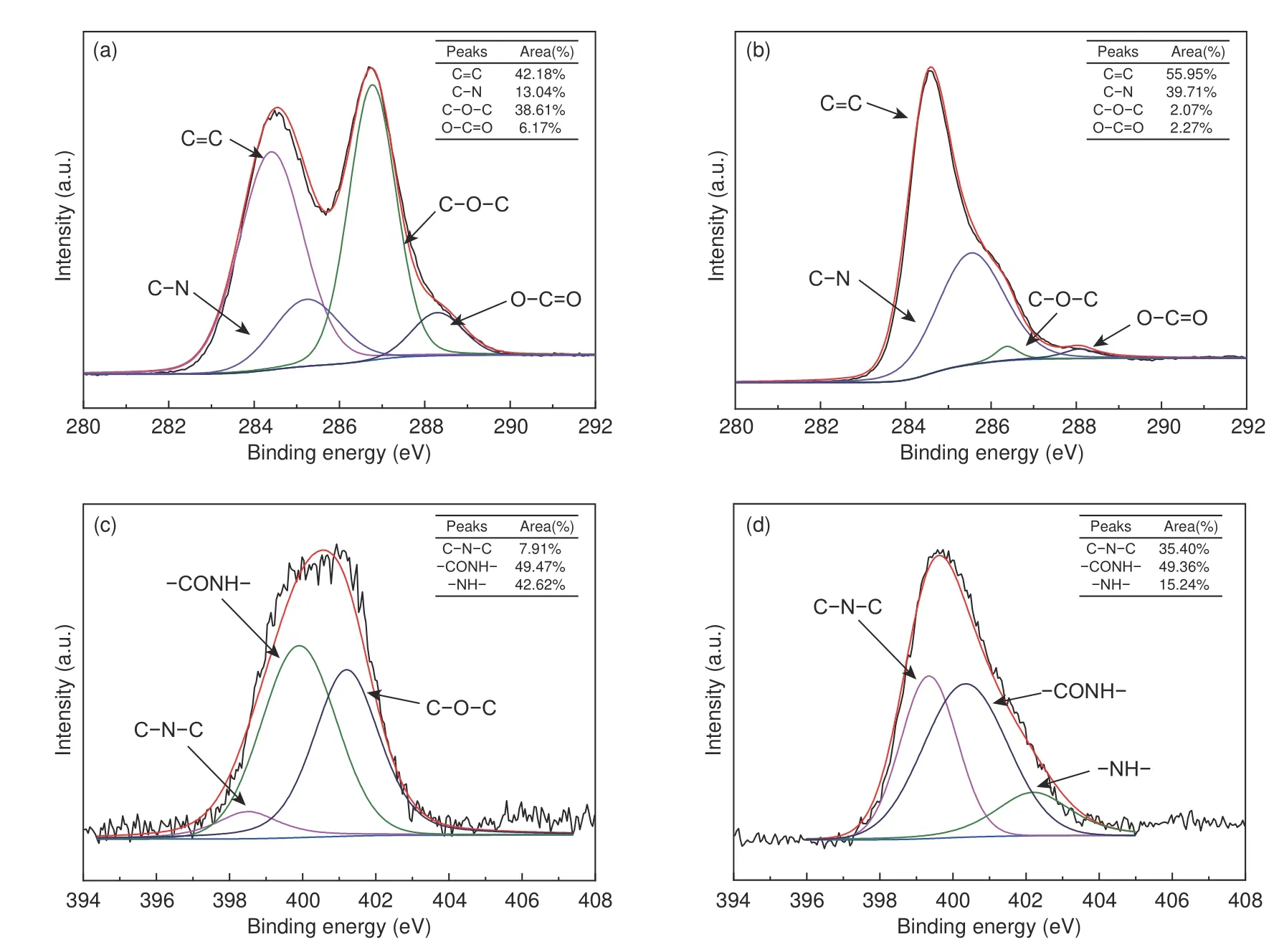
Fig.4 The XPS spectroscopy of (a,b) C 1s spectra of A-mGO/PAA and A-mGO/PI.(c,d) N 1s spectra of A-mGO/PAA and A-mGO/PI composite film.
The influence of the modification and the structural integrity of the composite films is further examined by Raman spectroscopy,as illustrated in Fig.5.TheD-band at~1 350 cm−1is attributing to the sp3-hybrid C atoms at the defects and theG-band centered at~1 580 cm−1is corresponding to the firstorder scattering ofE2gmode of sp2-hybrid carbon domains[35,36].The details of intensity ratios ofDandGband (ID/IG),as summarized in Table S2,reveal that the modification of GO leads to a poor crystallinity corresponding to a slight increase inID/IGfrom 0.959 7 to 1.038 4 due to the grafting of APB-134 onto the GO sheets.Moreover,ID/IGof A-mGO/PAA film with different amounts of PAA displays a negligible change around 0.998 3 suggesting the introduction of PAA does not give rise to extra defects on AmGO sheets.But after the graphitization treatment,as shown in Fig.5b,theG-band of each sample becomes sharper with an additional 2D peak.TheID/IGvalue,as concluded in Fig.5d,has a significant decrease from 0.128 9 to 0.065 3 indicating that the defects in A-mGO are gradually restored as well as leads to the coalescence of graphene sheets due to the existence of PI between A-mGO sheets.Notably,when the loading of PAA changes from 1% to 7%,theID/IGvalue is getting lower.The value ofID/IGof g-AmGO/PI-7% is only 0.065 3.But with further addition of PAA to 10%,theID/IGratio shows a rise to 0.131 4 indicating that the excessive PAA leads to aggregation and disordered structure during the graphitization treatment.Moreover,the grain size of graphene sheets (La) in each sample is calculated according to the following Eq.(3)[17,37]:
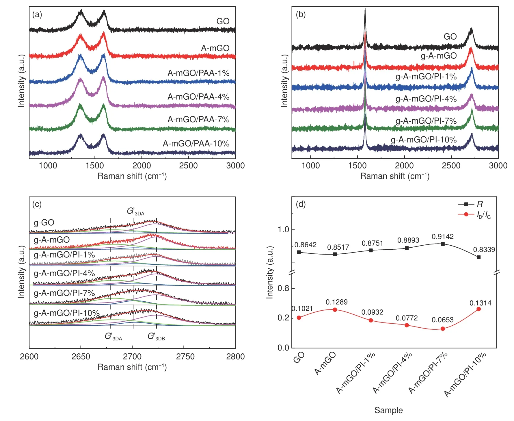
Fig.5 Raman spectroscopy of (a) A-mGO-PAA.(b) g-A-mGO-PI films.(c) fitted 2D band and (d) ID/IG ratio and R value of g-A-mGO/PI film.

whereλis the wavelength of laser (532 nm).As listed in Table S2 (Supporting Information),theLavalue of g-A-mGO/PI-7% film also exhibits the largest grain size of 294.40 nm,while that of g-GO is only 188.29 nm.The increase in grain size indicates the introduction of PI can successfully weld up adjacent mGO sheets resulting in a larger lateral size.But with the over loading of PI,theLavalue of g-AmGO/PI-10% is only 146.31 nm.Because the turbostratic structure formed by excessive PI would diminish the lattice restoration degree during the graphitization.
Additionally,the 2Dpeak at~2 700 cm−1ascribed to a double-resonance Raman process is fitted to infer the interplaner crystalline coherence length[38].As the high-resolution fitted curves displayed in Fig.5c,the 2Dpeak of each sample can be deconvoluted into three Lorentzians components,G’2Dat~2 700 cm−1corresponding to the turbostratic structure,G’3DA(~2 670 cm−1) andG’3DB(~2 720 cm−1) corresponding to the AB Bernal stacking of graphene sheets,respectively[39].The degree of ordered structure of each sample can be evaluated by theRvalue given by the Eq.(4):

whereIG′3DBand IG′2Drepresent the intensity ofG’2DandG’3DBpeaks.As summarized in Fig.5d,theRvalue of g-A-mGO/PI-7% is 0.914 2,the highest among all samples,suggesting PI as a solder could enhance the structural integrity of the composite film.But that of g-A-mGO/PI-10% has dramatically decreased to 0.833 9,even lower than that of pristine graphene film,corresponding to a higher proportion of turbostratic structure due to the aggregation of excessive PI between the mGO layers.The Raman spectroscopy indicates that the modification of GO and further molecular welding by PI can enlarge the grain size of graphene sheets and restore the defects leading to a coalescent and oriented structure.The presence of PI offers effective pathway for phonon transportation,but the excessive amount of PI would agglomerate on the surface of mGO leading to intensive phonon boundaries scattering.The results are quite in line with the XRD patterns.
3.3 Thermal performances and flexibility of g-AmGO/PI film
The in-planeκof each sample at room temperature is determined by the laser flash analysis (LFA 467 NanoFlash,Netzsch) as summarized in Fig.6a.Theκvalue of g-GO film is only 740 ± 34 W m−1K−1.After the modification by APB-134,theκvalue of g-AmGO shows a decrease to 668 ± 45 W m−1K−1due to the grafting of APB-134 impeded the ordered stacking of graphene sheets.But with the in-situ synthesis of PI,theκvalue of g-A-mGO/PI film displays a sequential increase from 1% to 7%.Notably,the highestκvalue of g-A-mGO/PI-7% reaches 1 102 ±21 W m−1K−1,that is 48.92% higher than that of pristine g-GO film.Additionally,the bulk density of g-A-mGO/PI film,as concluded in Table S3 (Supporting Information),suggestes that such a“graftingwelding”process of PI has successfully coalesced mGO sheets into larger ones and reduced the phonon scattering between mGO sheets interface.Herein,as listed in Table S4 (Supporting Information),compared with the recently state-of-the-art thermal conducting films,this value is also exceeded than that of the pristine graphene film prepared by vacuum filtration[40]or slurry casting method[9].The presence of PI for connecting the GO sheets offers an effective pathway for phonon transportation in graphene film to achieve the considerable enhancement inκ.Furthermore,the modification of GO offers terminal -NH2groups at the boundaries or the surface of mGO sheets,acting as reactive sites for further covalent connecting of mGO.Therefore,it is also superior than that of graphene/PI film (~802 W m−1K−1) via direct molecular welding method in our previous work[41].But when the amount of PI is 10%,the κ value of g-A-mGO/PI-10% has dramatically reduced to 620 ±21 W m−1K−1indicating the excessive PI has agglomerated between graphene sheets and leads to extra phonon scattering to reduce the thermal performances.
The anti-bending performance of g-A-mGO/PI film is determined by the electrical resistance ratio(R/R0,whereR0represents the resistance without bending) at the bending crease via a four-point-probe instrument (RTS-9,Scientific Equipment &Services).Each sample is measured 5 times to calculate the averageR/R0,and the error bar represents to the standard deviation.As shown in Fig.6b,theR/R0value of pristine g-GO film shows a remarkable increase to 1.4 only after around 1 000 times bending.After a 2000-cycle bending test,the resistance ratio has reached~1.8,suggesting the inner structure of g-GO film is broken.While the g-A-mGO/PI film treated by the“grafting-welding”survives from a 2 000 cycles with a small radius bending test.The g-A-mGO/PI-7% film only exhibits a slight change ofR/R0(~1.1) indicating an excellent anti-bending performance.
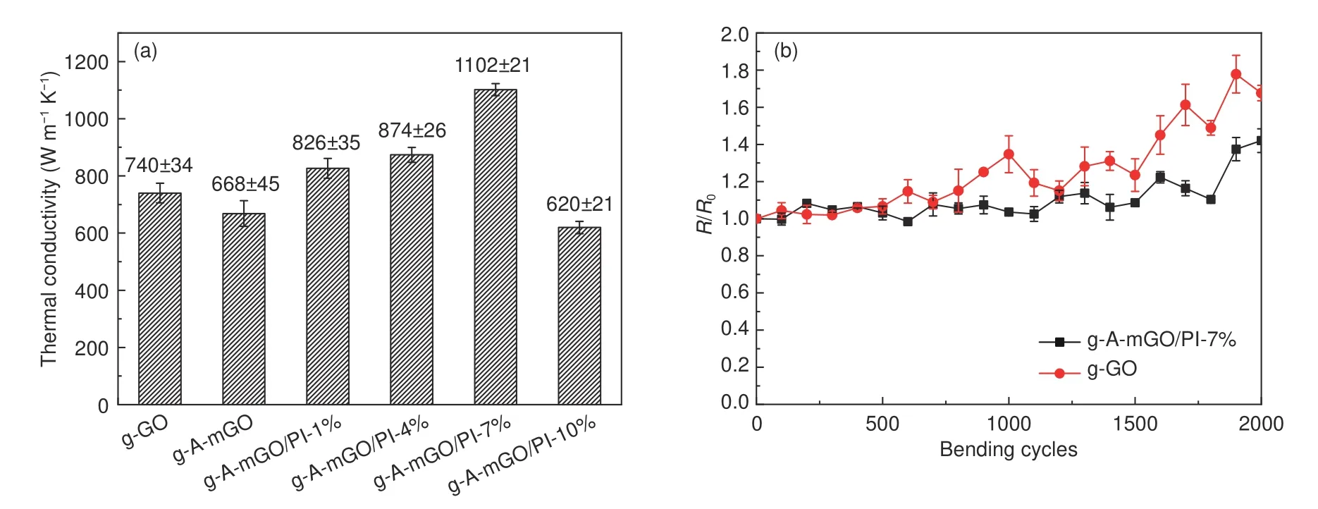
Fig.6 (a) The thermal conductivity of g-A-mGO/PI composite films and (b) The resistance ratio (R/R0) of g-A-mGO/PI composite films at the bending crease.(Each point was measured by 5 times to calculate the average R/R0)
3.4 The schematic illustration of modified“grafting-welding”process
The modification of GO by APB-134 and the model reaction based on A-mGO and the monomer PMDA is carried out as illustrated in Fig.7.According to the structural characterization,GO is firstly grafted by APB-134 via an amination reaction between the carboxyl and the terminal amine groups.(Fig.7a) The following in-situ“welding”process can be divided into three parts as shown in Fig.7b.At first,PMDA is protonated at the amidic oxygen to form the intermediate (1).Then,the formation of AmGO/PAA is involved a two H2O molecular hydrolytic reaction path via forming hydrogen bond interaction[42,43].The feasible structure of the A-mGO/PAA is illustrated as structure (2).During the imidization treatment at 250 °C,A-mGO/PAA is initiated by protonation of the carbonyl groups in ― COOH,followed by the proton transferring and dehydration synthesis to form imide C―N―C groups (structure(3))[43,44].The structural illustration of the“graftingwelding”A-mGO/PI is displayed in Fig.7c.Due to the presence of PI,the adjacent GO sheets are connected with larger lateral size.Moreover,it also provides an effective pathway for phonon ballistic transportation resulting in a superior thermal dissipating performance and excellent flexibility.
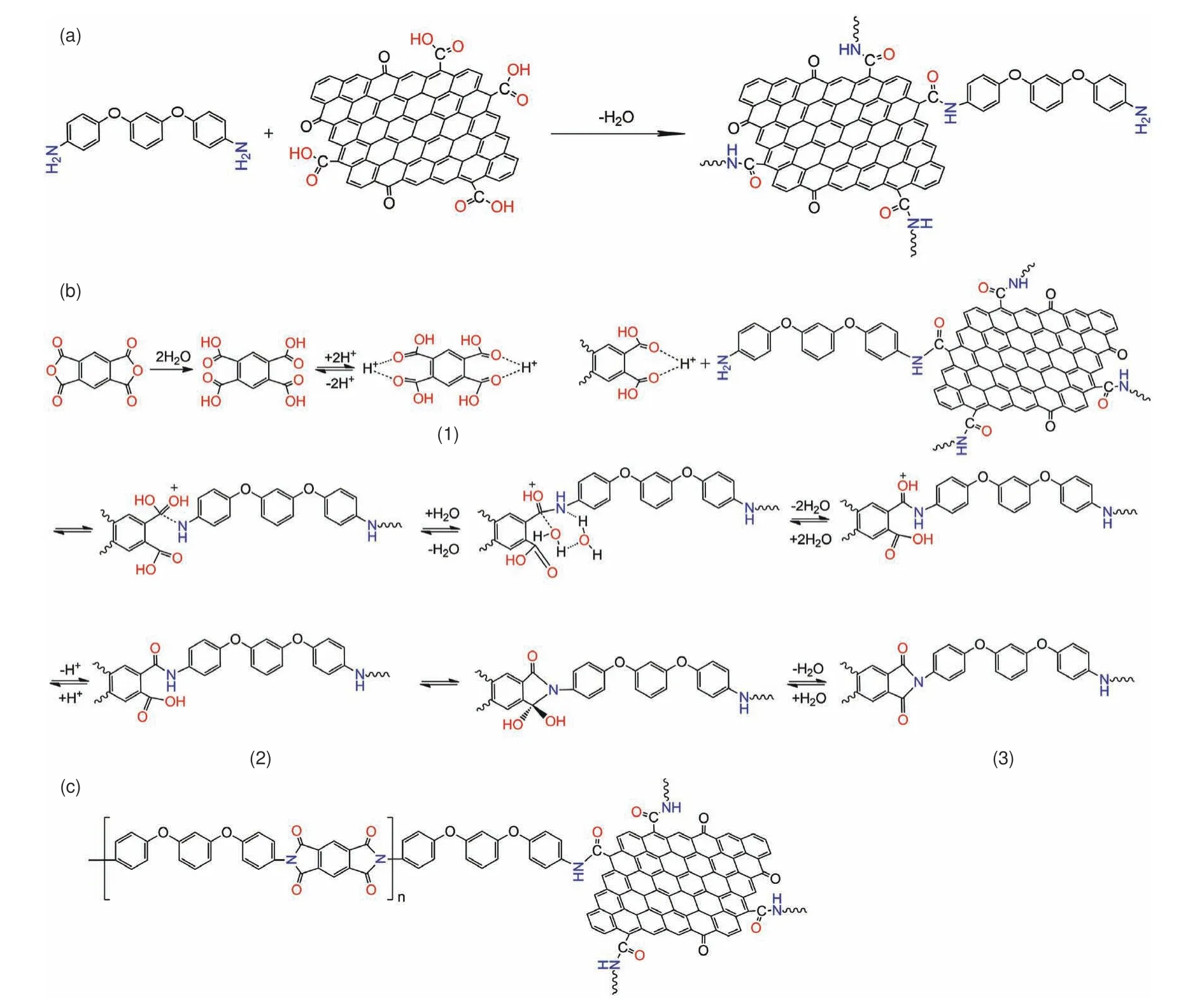
Fig.7 Proposed schematic representation of“grafting-welding”of A-mGO/PI.(a) Illustration of the modification of A-mGO,(b) Reaction between A-mGO and PAA during the imidization treatment and (c) The final structure of welded A-mGO/PI.
4 Conclusion
In summary,a novel one-pot preparation of modified graphene/polyimide is exploited for highly efficient thermal management.APB-134 is applied not only as a functional reagent,but also as a monomer for in-situ synthesis of PI to connect GO sheets.Based on such a chemical“grafting-to”modification of amine groups to GO sheets,APB-134 offers sufficient reactive sites for further covalent linking of GO sheets.The as-obtained g-A-mGO/PI-7% film exhibits excellent flexibility over 2000-cycle-bending test and superior in-planeκof 1 102 ± 21 W m−1K−1improved by 48.92% than that of pristine g-GO film.Last but not the least,we believe that the“graftingwelding”strategy shows a promising way to utilize GO or its functionalized derivatives in fabricating thermal conducting materials with high performance.
Acknowledgements
The authors are thankful to Shanghai Sailing Program (20YF1432100),Shanghai Scientific and Technological Innovation Project (19JC1410400) and Innovation Program of Shanghai Municipal Education Commission (2019-01-07-00-07-E00015) for their financial supports to this study.
- 新型炭材料的其它文章
- TiC-modified CNTs as reinforcing fillers for isotropic graphite produced from mesocarbon microbeads
- A review of three-dimensional graphene networks for use in thermally conductive polymer composites:construction and applications
- A mini review:application of graphene paper in thermal interface materials
- Thermal conductivity of graphite nanofibers electrospun from graphene oxide-doped polyimide
- Microstructure of high thermal conductivity mesophase pitch-based carbon fibers
- Properties and microstructures of a matrix graphite for fuel elements of pebble-bed reactors after high temperature purification at different temperatures

