A review of three-dimensional graphene networks for use in thermally conductive polymer composites:construction and applications
WU Ni,CHE Sai,LI Hua-wei,WANG Chao-nan,TIAN Xiao-juan,LI Yong-feng*
(State Key Laboratory of Heavy Oil Processing, China University of Petroleum, Beijing 102249, China)
Abstract:As the power consumption and heat generation of electronic devices continue to increase,higher demands are being placed on thermal management materials for heat dissipation.Graphene has been widely used as a thermally conductive filler to improve the thermal conductivity of polymers.However,the poor dispersibility of graphene nanoplates in polymers dramatically limits their practical use in thermal management.A promising strategy to increase the thermal conductivity of polymer composites is to construct interconnected three-dimensional graphene networks.This review summarizes the recent advances in the construction and applications of three-dimensional graphene-based polymer composites and ways to improve their thermal conductivity.The current challenges and prospects for the preparation and applications of these materials are considered.
Key words:Three-dimensional;Graphene;Polymer composites;Thermal conductivity;Constructions and applications
1 Introduction
Along with the technological development in 5G,big data,artificial intelligence,etc.,the power density of electronic devices progressively increases,thus raising the urgent demand for efficient thermal management systems with high thermal conductivity (TC)to ensure the efficiency,reliability,safety,durability,and stability[1,2].
Polymers have attracted great attention owing to their impressive properties,such as light weight,low cost,high flexibility and excellent processibility.However,most polymers have intrinsically inferior TC (0.1–0.5 W m−1K−1) due to their amorphous side chain[3].There are two general strategies to improve the TC of polymers[4]:(i) morphology engineering of polymer chains and (ii) filling the polymer matrix with highly thermally conductive fillers.However,the first strategy shows limited applicability because it is only valid for polymers with linear molecular chains[1].In comparison,combining polymers with highly thermally conductive fillers is superior in efficiency,conveniency,and wide applicability.Graphene-based composites are recognized as promising heat dissipation materials for the exceedingly high TC (~5 300 W m−1K−1) and the outstanding mechanical properties of graphene[5].It requires high filler concentrations (20–30 wt%) of randomly dispersed graphene nanosheets to construct thermally conductive pathways in the polymer matrix.However,at high filler loading,the poor dispersity of graphene nanosheets causes severe phonon scattering and considerable interfacial thermal resistance,leading to only moderate TC enhancement[6],deteriorated processability,and elevated cost[7].Three-dimensional interconnected fillers are proven to provide maximum TC enhancement with minimal filler loading due to greatly improved phonon transfer efficiency and reduced interface thermal resistance[1].Up to now,tremendous efforts have been made in the construction of three-dimensional graphene networks (3D GNs) to enhance the TC of polymer composites.Numerous reviews on 3D graphene have been reported[8–12],but they specifically focus on the construction strategies of 3D graphene frameworks.The comprehensive reviews about their promising thermal management applications are rare.
In this review,we mainly focus on the construction and applications of 3D GNs in thermally conductive polymer composites.Moreover,the strategies to improve the heat conduction of 3D graphene-based polymer composites (GPCs) are discussed.A schematic summary of 3D heat-conducting GNs is shown in Fig.1.
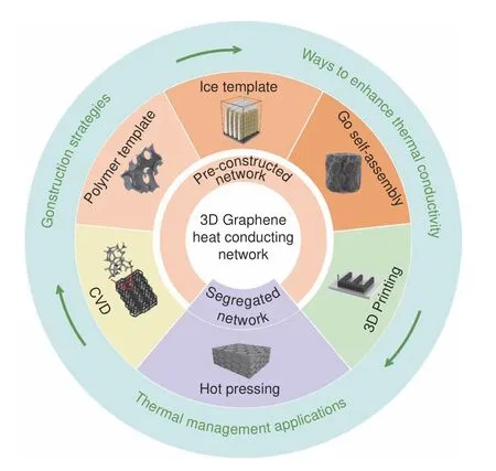
Fig.1 Schematic illustration of various 3D graphene networks for highly thermally conductive polymer composites.
2 Preparation of 3D GNs for thermally conductive polymer composites
The critical characteristic of 3D network architecture is the continuous pathways of fillers throughout the matrix with more than one or random orientations.3D GNs are constructed by numerous interconnected and curved few-layer graphene sheets or an integrated few-layer graphene sheet with a distorted and porous structure[13].According to the network formation process,the fabrication of 3D GNs in polymer composites can be classified into two typical strategies[14]:(1) pre-constructed networks and backfilling and (2) segregated networks.The former category involves a two-step process that utilizes the prefabricated monolithic 3D GNs as a skeleton,followed by the infiltration of liquid phase polymers or precursors into the pores of the skeleton.The latter category is associated with the segregated 3D GNs featuring a continuous filler distribution on the surface of polymer particles,which can be obtained directly by onestep thermal compression of the graphene-encapsulated polymer particles.
2.1 Pre-constructed 3D GNs
The preparation of pre-constructed 3D GNs can be separated into dry (based on chemical vapor deposition (CVD)) and wet (solution-derived assembly)methods[15].The wet method usually applies graphene/graphene oxide (GO) as the starting material to assemble the 3D frameworks.Based on the templates,it can be subdivided into polymer foam/ice template assembly and self-assembly (template-free).
2.1.1 CVD methods
CVD on 3D catalytical templates is one of the most widely used bottom-up synthetic strategies to fabricate high-quality 3D GNs[16].Generally,gaseous hydrocarbons are deposited and decomposed on the surface of the 3D catalytical template to generate the interconnected film.A continuous 3D graphene structure can be obtained after template removal,while maintain the morphology of the original template.Various templates have been reported for CVD graphene growth such as metals (Fe[17],Co[18],Ni[19],Rh[20],Ru[21],Cu[22],etc.),metal oxides (Al2O3[23],MgO[24],CaO[25],MnO[26],etc.) and non-metal oxides(SiO2[27],etc.).
Zhang’s group was the first to apply 3D graphene foam (GF) prepared by the CVD method to thermal interface materials (TIMs) (Fig.2a)[28].The free-standing 3D GF was grown on nickel foam with C2H2as carbon feedstock,where the thermal interface resistance was as low as 0.04 cm2K W−1.Similarly,Zhou et al.employed the nickel mesh network as the template to acquire GF by CVD process and fabricated the corresponding 3D GF/epoxy composites(Fig.2b)[29].With only 0.14 vol% graphene,the GF/epoxy composite achieved a TC of 0.52 W m−1K−1.To further improve the thermal conduction of polymer composites,Wu et al.reported the synthesis of continuous GF networks filled with aligned graphene nanoplates (Fig.2c)[30].The resulting natural rubber(NR) composites exhibited an extremely high in-plane TC of 10.64 W m−1K−1with a filler loading fraction of 6.2 vol% due to the synergistic effect between 3D GF and graphene nanosheets.
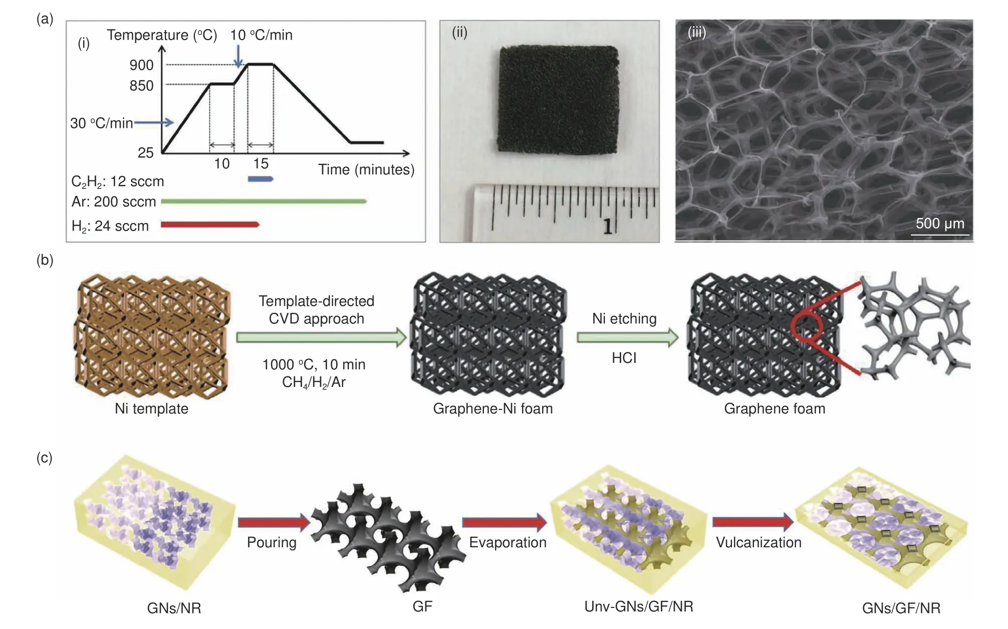
Fig.2 (a) (i) Growth profile of 3D GF by CVD using Ni foam as the template,(ii) Photo image of as-produced free-standing 3D GF film after removal of Ni template by chemical etching and (iii) SEM of free-standing GF[28].(b) Flowchart for the preparation of graphene foam[29].(c) Schematic for the synthesis process of GNs/GF/NR composites[30] .(Reproduced with permission).
2.1.2 Assembly methods
(1) Polymer foam template assembly
Compared with the CVD method mentioned above,the polymer template-assisted assembly is a more facile and energy-efficient way to construct 3D GNs by assembling GO/graphene sheets on the surface of polymer foam at low temperatures.After template removal,the GO/graphene sheets are expected to inherit the continuous network structure of porous polymer foam and generate 3D frameworks.The commonly used porous polymer templates include polyurethane (PU) foam[31],melamine foam (MF)[32],pitch[33],aromatic polyimides[34],etc.
Liu et al.prepared the GF with a sacrificial PU sponge template and then impregnated epoxy into the GF structure (Fig.3a)[35].At a low graphene loading of 6.8 wt%,a super high TC of 8.04 W m−1K−1was achieved.However,homogeneous assembly while realizing large-scale production remains challenging through the conventional dipping method.Dai et al.recently adopted a dual-assembly strategy to obtain highly ordered graphene skeletons.Graphene was uniformly assembled from the outer surface to the central region of PU sponges using a self-developed roller device (Fig.3b)[36].After template removal,the dual assembled graphene framework (DAGF) achieved a record-high TC of 62.4 W m−1K−1for the polymer composites at a graphene loading of about 13.3 vol%.Additionally,polymer templates tend to have favorable compression resilience.Hence,the retention of polymer template would impart elasticity to the 3D architecture so that the network structure and TC could be easily controlled by shape deformation.For example,Qin et al.developed flexible double-continuous graphene and polymer networks with superelasticity and regularity (Fig.3c-d)[37].Under the 3D compression,the TC value of the polydimethylsiloxane(PDMS) matrix composite reached a maximum TC of 2.19 W m−1K−1with a 70% compression ratio at a graphene loading of 4.82 wt%.
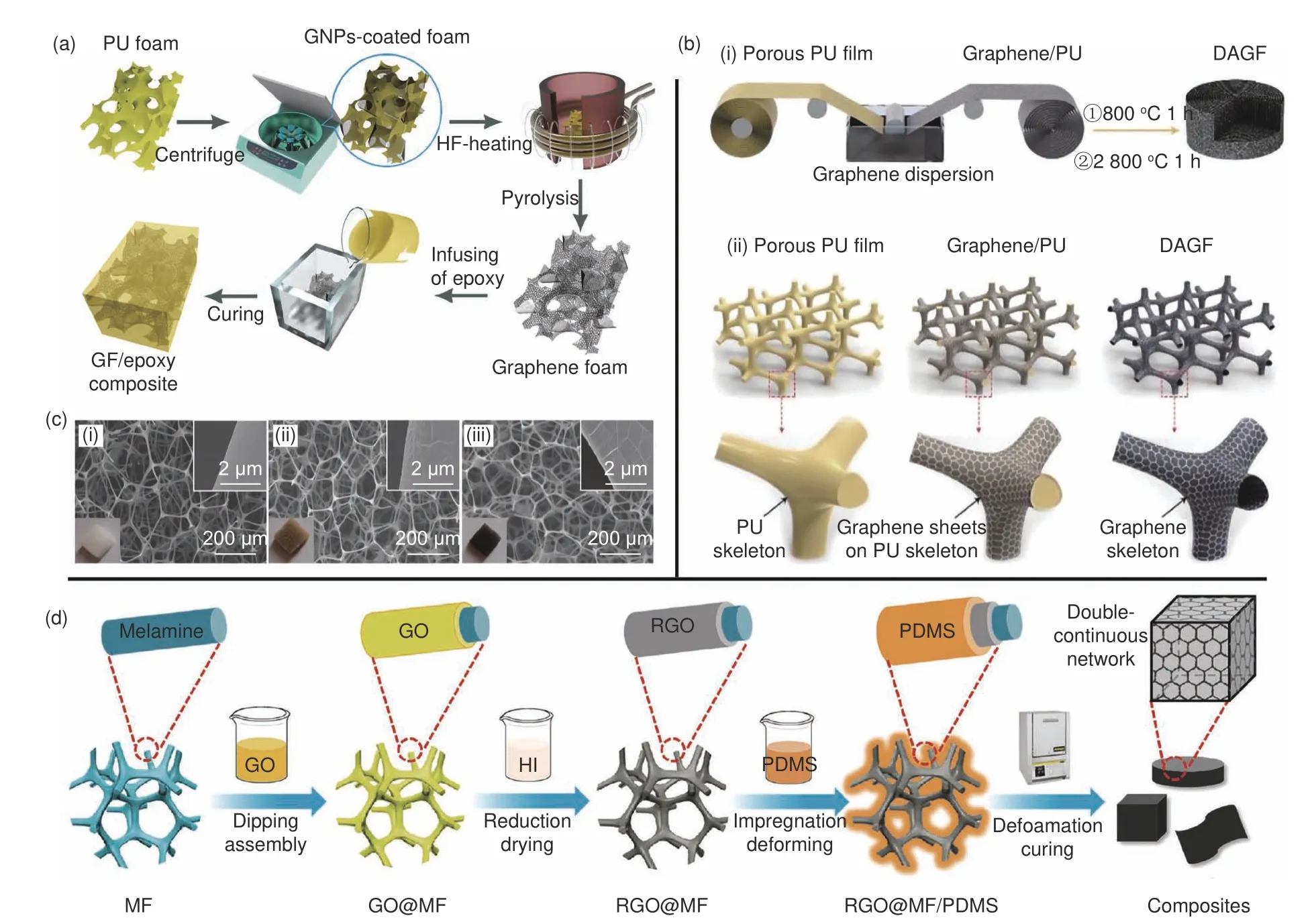
Fig.3 (a) The preparation process of the GF/epoxy composite[35].(b) Schematic illustration of (i) fabrication process of the DAGF and (ii) the corresponding structural change of each step based on the proposed dual-assembly method[36].(c) SEM images of (i) MF,(ii) GO@MF and (iii) reduced GO (RGO)@MF[37].(d) Illustration of the overall preparation procedures of the polymer nanocomposite[37].(Reproduced with permission).
(2) Ice template assembly
Compared with the CVD method,the ice template method is energy-efficient and cost-effective because high-temperature annealing or chemical etching is not required.Ice-templated assembly strategy is a directional freeze casting technique to obtain vertically aligned 3D GNs.GO nanosheets were expelled by vertically grown ice crystals driven by the temperature gradient during the freezing process,achieving phase separation and assembly into interconnected networks at the phase interface.Subsequently,the ice crystals are removed by sublimation,and the pores are retained to generate vertically aligned structures after the freeze-drying process,which can be used as thermally conductive fillers to dramatically boost the heat conduction of polymer composites along the vertical direction[38].
Min et al.synthesized an excellent thermally conductive phase change material (PCM) with anisotropic high-quality graphene aerogels by directional freezing GO and polyamic acid salt (PAAS) slurries and freeze-drying (Fig.4a)[39].The longitudinal TC of the obtained composite reached up to 8.87 W m−1K−1.Moreover,Yao et al.constructed a preferentially orientated hybrid skeleton through ball milling boron nitride (BN) and GO and subsequent directional freezing (Fig.4b)[40].At a filler addition of 13.16 vol%,the resulting epoxy composite presented a high throughplane TC of 5.05 W m−1K−1and excellent electrical isolation property (>1012Ω cm).The integration of thermally conductive yet electrically insulating BN into 3D graphene led to promising applications in TIMs for microelectronic heat dissipation.

Fig.4 (a) Schematic illustration of the fabrication of anisotropic high-quality graphene aerogels[39] and (b) Fabrication and microstructure of 3D BNrGO/epoxy composites:(i) the fabrication of 3D BN-rGO/epoxy composites,(ii) optical and (iii) cross-sectional SEM images of 3D BN-GO skeleton,(iv) SEM image showing the presence of BN large through-plane connected layers of GO and (v) SEM image of fractured surface of 3D BN-rGO/epoxy composites[40].(Reproduced with permission).
(3) Self-assembly
Compared with template-assisted assembly methods,self-assembly to fabricate 3D GNs shows advantages in simple template-free synthesis and low cost.The typical self-assembly preparation involves the gelation of GO dispersions followed by reduction.It is worth mentioning that the two processes can take place either simultaneously or successively[13].In a uniform and stable GO dispersion,interaction balance exists between the binding attraction among the hydrophobic planes and the electrostatic repulsion of the oxygen-containing groups.If the equilibrium breaks,the GO flakes will spontaneously approach each other,forming hydrogels with self-supporting structures[15].According to the driving force that triggers the gelation,the synthesis methods could be broadly grouped into the hydrothermal method,chemical reduction,and crosslinking.
The hydrothermal method.During the hydrothermal synthesis,oxygen groups of GO are gradually eliminated at moderate high temperatures(~90–200 °C) and a graphene hydrogel is formed by self-assembly[13].
A typical fabrication procedure of a graphene aerogel by hydrothermal reduction is shown in Fig.5a[41].The additional step of graphitization is optional for eliminating defects of rGO and further improving thermal conduction.In another work,3D BN/graphene frameworks (BGFs) were synthesized through hydrothermal reduction[42].In this composite(PBGF),3D GF served as the template for BN fabrication to construct the smooth 3D thermal conduction path.Besides,BN modulated the morphology of graphene nanosheets and improved the compatibility between the filler and matrix (Fig.5b).Compared with the polyamide-6 (PA6) composite containing 6.8 wt% graphene,the addition of 1.6 wt% BN increased the TC by 87.6%.
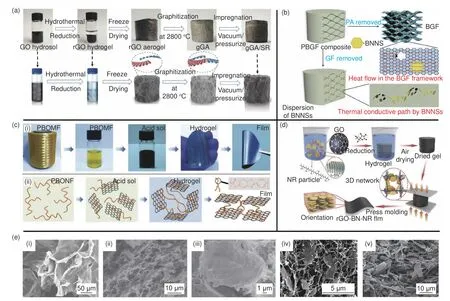
Fig.5 (a) Diagrams of fabrication procedure for graphitized graphene aerogel (gGA)/silicon rubber (SR)[41].(b) Simulation schematic of the thermal conductive path in PBGF composites[42].(c) Preparation and structure of graphene/PBONF[49].(d) Schematic illustration of the overall fabrication procedure of rGOBN-NR film[45].(e) (i) Cross-section SEM images of gGA[41],SEM image of (ii) GF,(iii) BGF[42]and (iv) freezing dried hydrogel,showing a 3D PBONF network with homogeneously distributed GNS[49]and (v) SEM microstructure image of the dried gel of rGO-BN[45].(Reproduced with permission).
Chemical reduction.A typical reduction-induced assembly process is formed by adding reducing chemical agents (ascorbic acid[43]and HI[44]) into GO aqueous suspension.In principle,the hydrothermal reduction mentioned above is also a reduction-induced assembly method driven by heat and pressure.Different from hydrothermal reduction,chemical reduction induced self-assembly generally takes place at atmospheric pressure below 100 °C without the requirement of stirring.
Li et al.prepared a highly flexible rGO-BNNR composite film with excellent heat dissipation performance by chemical reduction with ascorbic acid (Fig.5d)[45].The resultant thermal conductive film showed a remarkable in-plane TC of up to 16.0 W m−1K−1at 250 parts load of BN per hundred rubber.
Crosslinking.Introducing cross-linkers in GO dispersions improves the bonding between GO flakes by forming π-π overlap,hydrogen bonding,electrostatic interactions,or covalent bonding to accelerate gel formation effectively.To date,various crosslinkers have been reported,such as metal ions[46],biomolecules[47]and polymers[48].
Wang et al.adopted sodium sulfate as the crosslinker to trigger the gelation of graphene and poly (pphenylene benzobisoxazole) nanofiber (PBONF) sol(Fig.5c)[49].With 70 wt% nacre-like layered graphene,the PBONF film displayed an outstanding in-plane TC of 133 W m−1K−1.In addition,some thermally conductive materials with positive charge can also work as cross-linking agents to promote the gelation of GO,such as amino-modified boron nitride nanotube (BNNT)[50]and amino-modified SiC[51].
2.1.3 Other methods
Except for the typical methodologies of CVD and assembly,other new methods have been developed recently to prepare 3D GNs,such as 3D printing[52],foaming approach[53]and liquid nitrogen driven assembly[54].Nguyen’s group firstly adopted 3D printing technology to directly manufacture low-cost thermal management devices with functional ink containing graphite nanoplatelets and carbon fibers(Fig.6a-b)[52].The lightweight heat sink by direct ink writing demonstrated a TC of about 2 W m−1K−1and an excellent storage modulus of 3 000 MPa.
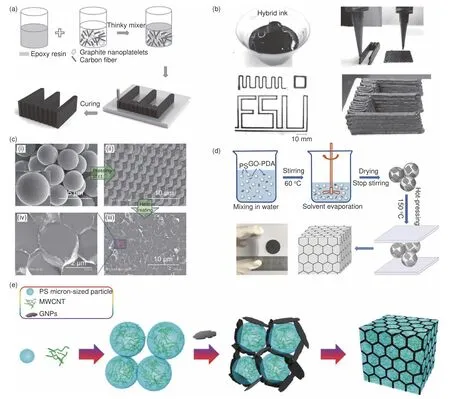
Fig.6 (a) Devices fabrication process.(b) Printing devices using hybrid ink[52].(c) SEM images of PS/GNP composite particles[56].(d) Schematic illustration of preparation of the PS/GO-PDA composites under high pressure with a continuous three-dimensional network (Inset:photograph of the PS/GO-PDA thin film[57]) .(e) Preparation procedures of (PS/MWCNT)@GNP nanocomposites with the segregated double network[58].(Reproduced with permission).
In summary,there are two primary approaches for the pre-construction of 3D GNs:CVD and assembly.CVD method produces high-quality graphene networks consisting of defect-free and covalently bonded graphene to enhance the TC of polymers significantly.However,the complicated template removal,high growth temperature and high cost limit the largescale production.In comparison,the assembly method is economical,convenient and beneficial for industrial production.However,the 3D GNs fabricated by this method have a relatively low TC enhancement,especially via the spontaneous GO self-assembly,which is ascribed to the defects,the weak interaction and the poor continuity of rGO assembled in the 3D framework.In terms of the polymer-template method,the retention of a polymer template in the 3D graphene architecture endows the 3D GPCs with high flexibility,but usually with the compromise in the TC of the complexes.Besides,regulation of the complex polymer/sheet interactions remains challenging.For the ice-template method,the unique vertically ordered structures equip 3D GPCs with significant improvement in through-plane TC,showing great advantages in the applications of TIMs.Moreover,the ice crystals are readily removed by freeze-drying without introducing new impurities.However,demanding experimental conditions are required to control the temperature and freezing rate during the freezing process that would affect the ice crystal growth and the ultimate architectures (in section 3.2).
2.2 Segregated 3D GNs
Apart from the pre-constructed 3D GNs,another effective strategy to construct 3D GPCs is to form segregated GNs in the matrix by one step.Typically,the matrix granules are first assembled with graphene nanoplates on the surface in a solution to build a coreshell structure (polymer spheres and graphene serve as core and shell,respectively).After dried,the composites are directly hot processed to build segregated 3D GNs by the connections of overlapping graphene nanosheets in the intergranular space,as shown in Fig.6c[55].Therefore,this method can also be termed as a polymer particle template-assembly method[56].
Yuan et al.prepared thermally conductive yet electrically insulating nanocomposites by encapsulating polystyrene (PS) with polydopamine (PDA)-modified GO followed by hot processing (Fig.6d)[57].The GO-PDA/PS composite exhibited a high cross-plane TC of 4.56 W m−1K−1and high electrical resistivity(1014Ω cm) at a low filler loading of 0.96 vol%.In another notable work,Wu et al.reported the fabrication of a synergistic segregated double network by pre-embedding multiwalled carbon nanotubes (MWCNTs) in polystyrene (PS),coating PS with graphene nanoplates (GNPs),and following hot-pressing(Fig.6e)[58].The TC of the obtained (PS/MWCNTs)@GNPs was almost 1.8 times as high as that of the randomly dispersed hybrid network composites.The significant enhancement was attributed to the synergistic effect between GNs and MWCNT networks along with the increased network density.
Compared with the complicated and time-consuming pre-constructed 3D GNs method,this“onestep”technology is convenient and straightforward for mass production.However,there are limitations in the polymers used.Generally,polymers with high melt viscosities (such as UHMWPE,NR and PS.) are usually employed to refrain from filler migration into their internal part,thus keeping the complete network separation in final composites[14].In contrast,polymers with low melt viscosity are not exploitable.Besides,this method also shares the disadvantages of polymer template assembly (in section 2.1.3).
3 Pathways to improve TC of 3D GPCs
In the fabrication of 3D GNs,there are two key factors affecting the TC of polymer composites:crystal quality and density of 3D GNs.Graphene with high crystal quality and low defect level endows the 3D GNs with remarkable intrinsic TC.Besides,highdensity 3D GNs favors the TC of the polymer composites.
3.1 Crystal quality of 3D GNs
3D GNs synthesized by CVD usually possess outstanding intrinsic TC due to their high crystallinity and purity[59].The graphene nanosheets grown in situ by CVD are connected with strong covalent bonds,resulting in intrinsically continuous networks with low interfacial thermal resistance.It is worth noting that the choice of template etchants has an impact on the crystal structure of 3D graphene synthesized by CVD.Pettes et al.utilized 3 different etchants (dilute HCl,Fe(NO3)3,(NH4)2S2O8) to remove the Ni support and found that the TC of the resulting low-density 3D GN increased from 0.26 to 1.7 W m−1K−1as the etchant ranged from the violent dilute HCl solution to the mild (NH4)2S2O8[60].This was attributed to the fact that bubbles generated from the Ni etching by HCl gave rise to considerable defects in 3D GNs (Fig.7a-b).As the etching process got slower and gentler with milder etchants,the improved structure quality was more beneficial to maintain the inherent TC of graphene in 3D GNs.Thus,a mild etchant was preferred to minimize the adverse effect on the crystal quality.
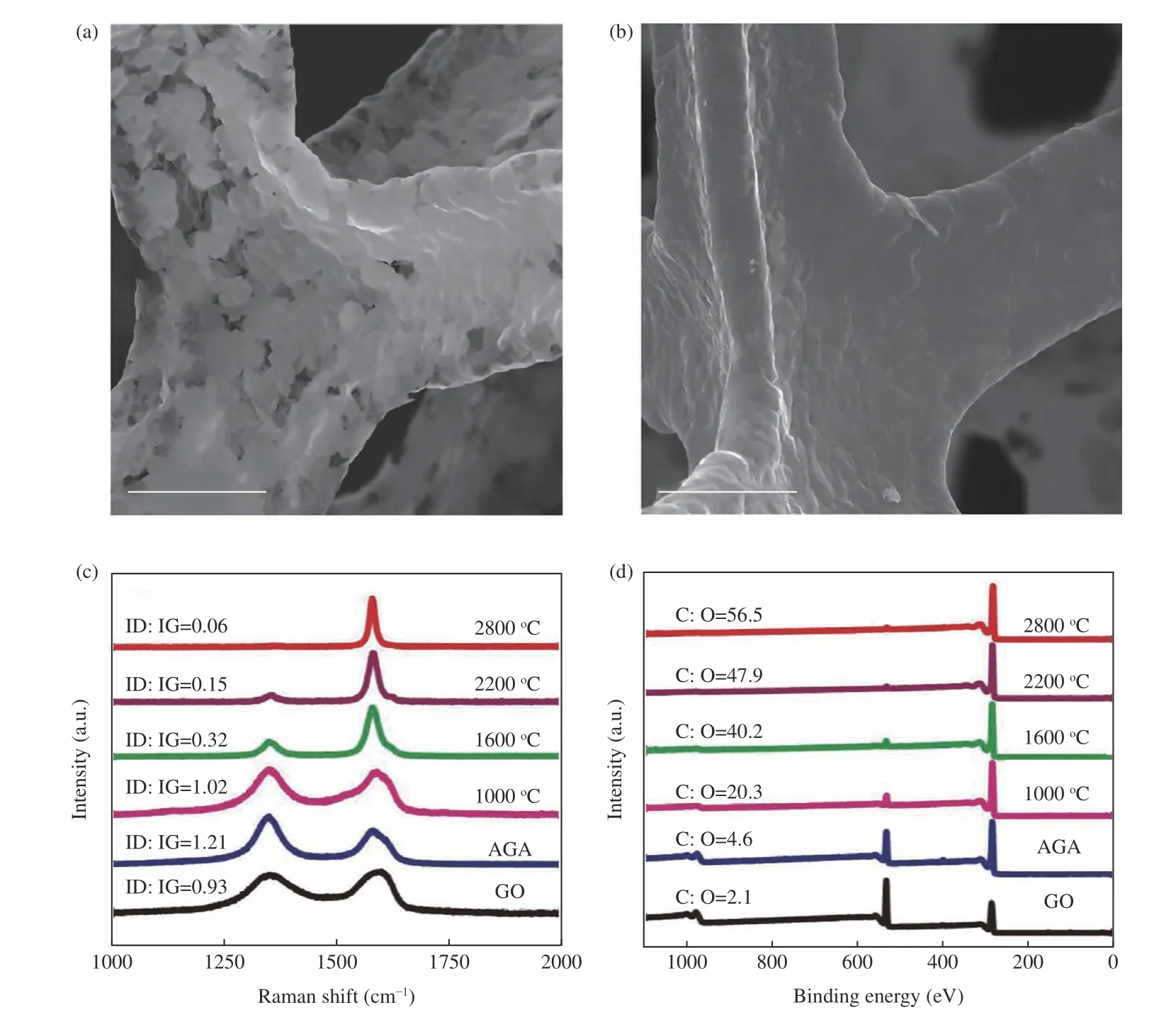
Fig.7 SEM images of the strut walls of freestanding GF samples after etching by (a) HCl and (b) (NH4)2S2O8[60] (All scale bars are 50 μm).(c) Raman spectra and (d) XPS spectra of GO,AGA,TAGA-1000,TAGA-1600,TAGA-2200 and TAGA-2800[63].(Reproduced with permission).
Unfortunately,the construction of 3D rGO networks by GO self-assembly cannot significantly improve the TC of polymer composites,although it is relatively convenient.The unsatisfactory performance primarily results from the inferior rGO network structures with abundant defects and oxygen-containing groups,resulting in severe phonon scattering and low heat transfer efficiency[61].High-temperature annealing has been demonstrated to be an effective treatment to improve the inherent TC of the networks[62].Li et al.prepared vertically aligned 3D GNCs by chemical reduction of GO,directional freezing,and subsequent thermal annealing under Ar atmosphere at different temperatures[63].The graphene quality was evaluated by the Raman spectroscopy (Fig.7c),in which theID/IGratio significantly decreased with increasing the annealing temperature,indicating the formation of graphene structures with less defects.The effective improvement of graphene quality was ascribed to the removal of residual oxygen-containing groups and the repairment of defects and vacancies by high-temperature annealing (Fig.7d),thus promoting the phonon transmission and the heat conduction.As a result,the epoxy composite with GNs annealed at 2 800 °C reached an extraordinary TC of 6.57 W m−1K−1in the vertical direction,which was three times higher than that of 3D GNs at the same loading (0.75 vol%) without high-temperature annealing.
3.2 Density of 3D GNs
The network density is another crucial factor that prominently affects the heat conduction properties of composites.It is reported that the transmission network with higher density facilitates the heat transfer more quickly and efficiently,thus improving the TC of composites[64].
In the method of GNs grown in situ by CVD,the low graphene loading in polymer composites (generally lower than 1 vol% with the density of~0.01 g cm−3)cannot provide sufficient heat transfer pathways due to the loose structure of the metal template.To break through the limitation,Shen et al.developed a new approach to fabricate the 3D graphene composite with a relatively high graphene content (8.3 wt%) by axially compressing 12 layers of Ni foam to increase the density of the template (Fig.8a)[65].After template etching and epoxy infiltration,the composite with a relatively high-density (~0.1 g cm−3) 3D multilayer graphene web (MGW) led to an exceptional in-plane TC of 8.8 W m−1k−1.
In the assembly method,the freeze-drying or supercritical drying is widely adopted to perfectly preserve the intact architectures and morphologies of 3D GNs.In contrast,air drying is an economical and convenient way to increase the density of graphene architectures by the capillary force-induced shrinkage.However,high densities mean small pore sizes of 3D structures,and very small pore sizes are not suitable for further impregnation of other functional materials or polymers[66].The resulting graphene monoliths by air drying are inevitably subjected to less controllable excessive shape shrinkage and structural collapse[67].Consequently,the porosity and pore size of resultant graphene framework are too small to be further impregnated with polymers within the porous graphene scaffold.To solve this problem,An et al.introduced graphene nanosheets into a rGO aerogel to prevent excessive volume shrinkage during air-drying procedure and make the 3D rGO interconnected network compact for efficient enhancement of thermal conduction(Fig.8b)[68].The resultant epoxy composite filled with a high-density (0.42 g cm−3) and vertically aligned rGO/GNP aerogel (19 vol%) achieved an exceptionally high through-plane TC 35.5 W m−1K−1,which was superior to those of composites filled with lowdensity graphene networks.
Additionally,the density of GNs can be controlled by the freezing rate during freezing casting.Li and co-workers froze graphene hydrogels at three different freezing rates (Fig.8c)[63].They found that the composite frozen at a faster directional freezing rate (by directionally freezing the hydrogel floating on liquid nitrogen) turned out to have the best heat conduction performance,which introduced a lower temperature and smaller ice crystals compared to the other two ways (the hydrogel was placed above the liquid nitrogen or on a copper cylinder immersed in liquid nitrogen).The 3D GNs with tiny pores and compact structures lead to an elevated TC of 6.57 W m−1K−1for the epoxy matrix.
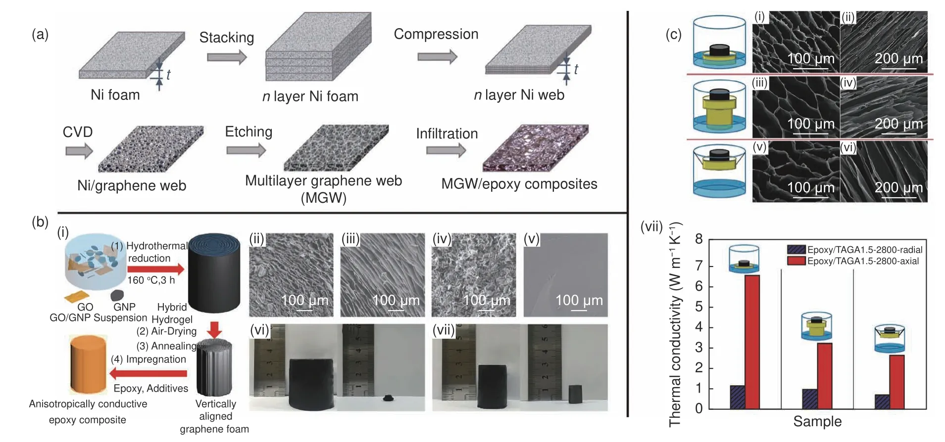
Fig.8 (a) Fabrication process of MGW and MGW/epoxy nanocomposites[65].(b) (i) Schematic illustrating the fabrication of anisotropically conductive epoxy composite,top-view SEM images of (ii) fGHF5,(iii) fGF,(iv) GHF5 and (v) GM.Digital images of hydrogels and corresponding foams dried under ambient conditions with different GO/GNP mass ratios of (vi) 1/0 and (vii) 1/5[68].(c) (i,iii,v) Top-view and (ii,iv,vi) side-view SEM images of TAGA-2800 prepared by using three directional freezing rates:(i,ii) floating the copper disk on liquid nitrogen,(iii,iv) putting the disk on a copper cylinder that is dipped in liquid nitrogen,and (v,vi) hanging the disk above the liquid nitrogen and (vii) epoxy/TAGA1.5-2800 with different directional-freezing rates[63].(Reproduced with permission).
Furthermore,building hybrid networks emerges as a promising strategy to boost the TC of composites through synergistic effect and dense thermal conduction network[69],which has been successfully applied in various fabrication methods as mentioned in section 2.The combination of thermally conductive fillers such as carbon-based materials (GNP[30],CNTs[70],CB[71]and CFs[72]) with 3D GNs takes full advantages of each filler and dramatically improves the TC of 3D GNs.In addition,thermally conductive but electrically insulating substances (BN[40],Al2O3[73],etc.) have also been incorporated into 3D GNs to enhance thermal conduction while maintaining low electrical conduction,which is vital for the practical applications of 3D GPCs in the microelectronics heat management field.
4 Applications of thermally conductive 3D GPCs
The graphene-based polymer composites have been widely used in various fields,such as electronic packaging materials,thermal interface materials(TIMs),phase change materials (PCMs) and battery separators.The highly thermally conductive 3D GPCs exhibit more advantageous thermal management performance.However,due to the complicated material fabrication,the practical applications of thermally conductive 3D GPCs are still limited.In this section,we summarize the recent progress of thermally conductive 3D GPCs in TIMs and PCMs as two examples to illustrate their potential applications.
4.1 TIMs
TIMs are used to fill the gaps and grooves between the heat-generating electronic unit (heater)and the heat sink surface to reduce the thermal contact resistance and allow smooth heat dissipation along the vertical direction.It is reported that a temperature drop of~20 °C in the heater could extend the device lifetime by an order of magnitude[74].Based on this,TIMs have been widely used in various electronic devices.For practical applications,TIMs are required to possess a high through-plane TC to maximize the heat transfer efficiency[75].
Dai et al.formulated a 3D GPC (DAGF5/PDMS)with a vertically aligned graphene structure,showing a superior through-plane TC of 60.2 W m−1K−1[36].A set of self-built apparatus was applied to test the actual heat transfer performance as a TIM (Fig.9a(i-ii)).The temperature difference (57 °C) between the heater without TIM and by applying DAGF5/PDMS composite greatly exceeded that of the other two state-ofthe-art commercial TIMs (Fujipoly XR-m (39 °C),Dexerials EX20000C7 (46 °C)),indicating its superior system cooling performance (Fig.9a(iii)).Moreover,damages from thermal stress such as the emergency of cracks and voids during thermal cycling could adversely affect the thermal and mechanical properties of composites.Therefore,a cyclic thermal shock test is highly indispensable for TIMs to evaluate the thermal stress damage in practical applications.Fig.9a(iv-v) indicated the remarkably thermal shock stability during consecutive heating and cooling cycles for 3 000 times and excellent thermal durability in a long-term TIM performance test (10 days).
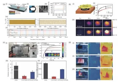
Fig.9 (a) (i) Schematic configuration of the TIM performance test system and the heat flow diffusion path along the vertical direction.(ii) The photograph and the cross-sectional SEM image of the DAGF5/PDMS composites.(iii) The heater temperature evolution versus the running time at the power density of 50 W cm−2.(iv) Thermal shock stability in cyclic heating/cooling tests and (v) thermal durability in a long-term TIM performance test (10 days) using DAGF5/PDMS as a TIM[36].(b) (i) Demonstration of PP/PDA/G composite as a thermal management material for heat dissipation of a LED lamp,(ii) The surface temperature variations of LED versus time,(iii) Comparison of infrared thermal images of LED integrated with PP/PDA/G and pure PP as thermal management materials[80].(c) (i) Photograph of the in-situ test system,(ii) Profiles of the surface temperature-time of a ceramic heater at 4 V with fan cooling (insets are IR images of the c-GF/PDA/APTS/PDMS composite),(iii) Breakdown strength and (iv) electrical resistivity of studied materials[79],(d) Visible light images and the corresponding IR images of CPUs integrated with self-made heat sinks[82].(Reproduced with permission).
Furthermore,electric insulation is another essential factor for TIMs in real applications.In order to prevent short circuit accidents in electronic devices,generally,the electrical resistivity and breakdown strength of TIMs are required to be higher than 1013Ω cm and 1 KV mm−1,respectively[76].Unfortunately,while the construction of the 3D graphene skeleton in the matrix significantly enhances the TC,the electrical conductivity of polymer composites unavoidably increases spontaneously.To address this problem,some researchers proposed a strategy of constructing the insulating layers (silica[77],alumina[78],PDA[79],and BN[40,42,45],etc.) onto graphene surfaces to suppress electric conductivity while preserving the excellent thermal properties.For example,Fang et al.coated GF with insulated PDA and obtained electrical isolating composite (c-GF/PDA/3-aminopropyltriethoxysilane (APTS)/PDMS) with an electrical resistivity of 9.02×10¹³Ω cm and a breakdown strength of 2.38 kV mm−1(Fig.9c)[79].Simultaneously,the composite also preserved incredible heat transfer capability,with a temperature difference of 18 °C compared to pure PDMS.Moreover,highly thermally conductive 3D GPCs have also been applied as TIMs in LED lamp and cellphone,revealing efficient thermal diffusion[30,80,81].For example,Song et al.prepared a 3D GPC (polypropylene (PP)/PDA/G) by a hot pressing method,which displayed a considerably high throughplane TC of 10.93 W m−1K−1[80].By taking advantage of this,the composite was used as a TIM for LED heat dissipation and exhibited excellent thermal management performance with a significant LED lamp surface temperature reduction (20 °C) compared to pure PP (Fig.9b).In short,these results all suggest that 3D GPCs provide preferable heat dissipation performance over some advanced commercial TIMs,and they are promising thermal management materials for nextgeneration electronic devices.
Besides TIMs,highly thermally conductive 3D GPCs can also be directly designed and applied as a heat sink for thermal management of devices[54,82].As shown in Fig.9d[82],a super flexible and highly thermally conductive film with a 3D hybridized structure was folded into a straight-fin heat sink and attached to a computer central processing unit (CPU).After CPU running for 40 s,the film folded heat sink demonstrated an apparently faster temperature hike than that of copper foil in both vertical and horizontal directions,implying superior heat extraction and practical heat transfer ability.The foldable carbon film origami heat sink showed great potential for heat diffusion in high-power and flexible electronic devices.
4.2 PCMs
PCMs,which store and release latent heat energy during the phase transition process within a narrow temperature range,are widely used as energystorage materials for effective thermal management.Commonly used polymers with phase transition include polyethylene glycol (PEG),paraffin wax (PW),unsaturated fats,and various esters[83].However,their practical applications are hindered by three disadvantages[67,84]:(1) poor TC (0.1–0.35 W m−1K−1),(2) the unstable shape above the melting point and (3) weak optical absorption during solar energy conversion.Embedding pre-constructed 3D graphene aerogel into PCMs can perfectly tackle these challenges owning to the high TC and light absorption of graphene coupled with the stable 3D structure supporting.Therefore,much attention has been paid to applying 3D GNs/PCMs in solar-thermal energy conversion and storage.
The enhanced thermal conductivity of 3D GNs/PCMs can enable the absorption or release of heat at relatively low-temperature gradients,resulting in higher efficiency in heat storage/release of the system[85].Yang et al.fabricated a highly thermal conductive and outstanding shape-stability PCM by encapsulating a hybrid graphene aerogel (HGA) into PEG[86].To evaluate the energy conversion ability,a typical light-to-thermal energy conversion experiment was carried out by simulating the solar radiation and recording the temperature change,as presented in Fig.10a(i-ii).The composite revealed a faster energy storage/release rate than PEG and a high light-tothermal conversion efficiency (θ) of 80%–90%(Fig.10a(iii-iv)).Compared with the white PEG(θ=0),the graphene-based PCM was black,which was conducive to absorbing radiation light and realizing energy storage.Moreover,the shape-stability is vital to prevent leakage,energy storage,and heat conduction.The hybrid graphene aerogel had a dense 3D network structure,which was beneficial to lock the PCM from leaking out and keep the shape stable during phase transition due to hydrogen bonds and capillary tube (Fig.10b).
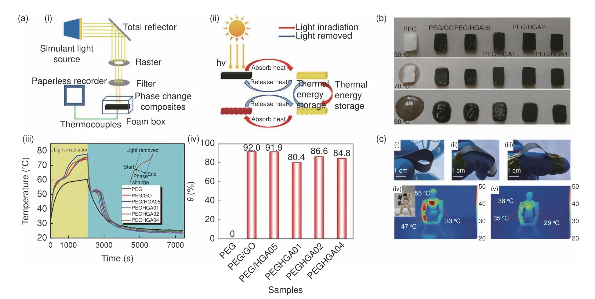
Fig.10 (a) Thermal energy storage and release:(i) Experimental setup for light-to-heat conversion,(ii) Schematic diagram of light-to-heat conversion and storage,(iii) Temperature evolution curves of pure PEG and composite PCMs and (iv) θ of the composite PCMs[86].(b) Shape-stability with increasing temperature[86].(c) (i-iii) The images of flexible GAF-PW CPCF,infrared imaging pictures of human model with GAF-PW CPCF coated on the one side of arm and chest (iv) under the irradiation for 210 s and (v) after removing the irradiation for 10 s[88].(Reproduced with permission).
Unfortunately,most prepared graphene aerogels are mechanically brittle,which adversely affects their application as PCMs for energy storage.The incorporation of polymer materials (MF[87],polyvinylidene fluoride-hexafluoropropylene (PVDFHFP)[88],etc.) is an effective way to give 3D graphene-based PCMs high flexibility so that they can be further applied to wearable personal thermal management.As shown in Fig.10c[88],the flexible 3D graphene aerogel based PCM (GAF-PW CPCF) is mounted on a manikin to absorb solar energy and generate heat for strengthening the adaptability of the human body in cold conditions.The flexible PCM behaved a visible temperature rise during irradiation and maintained a high temperature after the removal of irradiation,demonstrating a powerful solar-thermal conversion and storage capability.In addition,the mechanical properties of 3D graphene polymer composites can be strengthened by improving the graphene quality and enhancing the graphene-matrix interface interactions.The crystal quality of graphene can be improved by high-temperature annealing,resulting in higher graphene stiffness and therefore higher yield strength and Young's modulus[63,89].Moreover,surface modification of graphene(polyaniline[90],etc.) and the addition of cross-linking agents (poly (3-mercaptopropyl) methylsiloxane[91],etc.) are beneficial to enhancing the interfacial interaction between the three-dimensional filler and the substrate,resulting in better mechanical properties of 3D GPCs.
5 Conclusions and perspectives
The heat management materials are essential for modern miniaturized and integrated electronic devices.With excellent TC and mechanical strength,graphene is an ideal thermally conductive filler for polymer composites.Compared to the traditional polymer composites filled with randomly dispersed graphene nanosheets,constructing 3D GNs in polymer composites emerges to be a more effective strategy to achieve high TCs at relatively low filler loadings due to sufficient phonon transmission channels and reduced thermal resistance in the continuous interconnected 3D GNs.In this review,we summarized the recent advances in the thermally conductive 3D graphene-based polymer composites and mainly focused on the methodologies,strategies to enhance the TC,and potential applications in thermal management.A summary of the preparation methods,testing method,3D graphene density,thermal conductivity,as well as thermal conductivity enhancement efficiency of these 3D graphene-based composites are presented in Table 1.On this basis,the conclusions and perspectives are presented as follows:
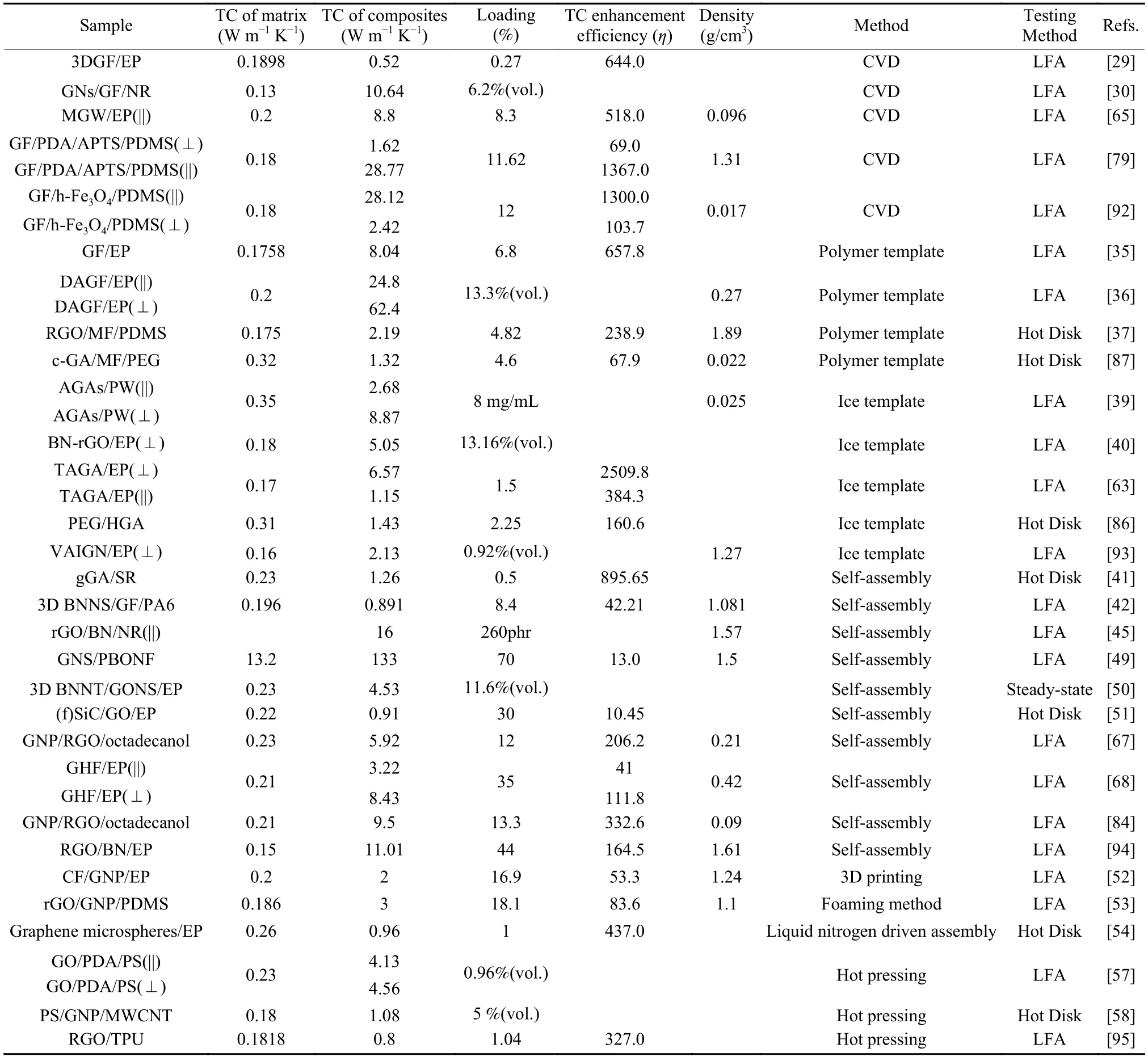
Table 1 Summary on thermal conductivities of polymer composites filled with 3D graphene prepared by different methods.
(1) Various strategies have been devoted to synthesize 3D GNs and their composites,mainly including CVD,assembly,and hot-pressing methods.Nevertheless,mass production of composites with outstanding thermal performance is still challenging.Therefore,it is necessary to modify the current preparation methods or develop new strategies to achieve simple,highly efficient,economical and mass-producible preparation of 3D GPCs.
(2) The degree of heat transfer depends on the quality and number of heat transfer channels.Although the network density can be improved by some methods such as compressing templates or air drying,the improvement is still limited.Therefore,improving the density of thermally conductive 3D structures remains to be the primary problem.
(3) High longitudinal TC and electrical insulation are two key performance factors for TIMs.Therefore,the construction of 3D graphene networks with longitudinally aligned structures and the incorporation of electrical insulating yet thermally conductive particles to suppress electrical conductivities of graphene are the future directions for TIMs development.For PCMs,the special structure of 3D GNs is favorable to the TC,absorption and anti-leakage of PCMs.However,the high cost and poor mechanical properties restrict the application of 3D GPCs in more fields such as building thermoregulation materials.Furthermore,incorporating other functional materialsto prepare hybrid networks emerges as a promising strategy to broaden the versatile applications of thermally conductive 3D GPCs.
Acknowledgement
We gratefully acknowledge the financial supports from the National Natural Science Foundation of China (Nos.21808240,21776308 and 21908245),and Science Foundation of China University of Petroleum,Beijing (No.2462018YJRC009).
- 新型炭材料的其它文章
- TiC-modified CNTs as reinforcing fillers for isotropic graphite produced from mesocarbon microbeads
- A mini review:application of graphene paper in thermal interface materials
- Thermal conductivity of graphite nanofibers electrospun from graphene oxide-doped polyimide
- One-pot modified“grafting-welding”preparation of graphene/polyimide carbon films for superior thermal management
- Microstructure of high thermal conductivity mesophase pitch-based carbon fibers
- Properties and microstructures of a matrix graphite for fuel elements of pebble-bed reactors after high temperature purification at different temperatures

