
A comprehensive review of miniatured wind energy harvesters
2021-07-28 06:15:46QuanWenXianmingHeZhuangLuReinhardStreiterThomasOtto
Namo Materials Science 2021年2期
Quan Wen ,Xianming He ,Zhuang Lu ,Reinhard Streiter ,Thomas Otto
a Key Laboratory of Fundamental Science of Micro/Nano-Device and System Technology,Chongqing University,Chongqing,400044,People's Republic of China
b Microsystem Research Center,Chongqing University,Chongqing,400044,People's Republic of China
c Fraunhofer Institute for Electronic Nano Systems(ENAS),Chemnitz,09131,Germany
Keywords:Energy harvester Wind energy Miniature wind-induced vibration energy harvester Energy coupling mechanism Performance enhancement mechanisms
ABSTRACT Following the current rapid development of the Internet of Things(IoT)and wireless condition monitoring systems,energy harvesters which use ambient energy have become a key part of achieving an energy-autonomous system.Miniature wind energy harvesters have attracted widespread attention because of their great potential of power density as well as the rich availability of wind energy in many possible areas of application.This article provides readers with a glimpse into the state-of-the-art of miniature wind energy harvesters.The crucial factors for them to achieve high working efficiency under lower operational wind speed excitation are analyzed.Various potential energy coupling mechanisms are discussed in detail.Design approaches for broadening operational wind-speed-range given a variety of energy coupling mechanisms are also presented,as observed in the literature.Performance enhancement mechanisms including hydrodynamic configuration optimization,and non-linear vibration pick-up structure are reviewed.Conclusions are drawn and the outlook for each coupling mechanisms is presented.
1.Introduction
The 2030 Agenda for Sustainable Development promoted and adopted by the United Nations Member States has set 17 Sustainable Development Goals,including affordable and clean energy[1].This has laid the basis for speeding up the quest for renewable energy sources,a hot topic this last decade.The massive use of fossil fuels and their negative impact on the environment has triggered research efforts tofind a solution without compromising our way of living.
Wind can be considered as simply air flow consisting of the many gases in our atmosphere.It obtains its kinetic energy from relatively large-scale phenomena,such as the rotation of the earth and temperature difference due to the unevenly distributed heating in the atmosphere.Many factors like undulating terrain can also in fluence its intensity distribution.Because of this,wind is considered as a sustainable energy source since it is renewable,widely distributed,and plentiful in nature.Increasing the usage of wind energy could lead to lower dependence on fossil fuels,and it would gradually decrease global greenhouse gas emission.It is reported in the World Energy Outlook 2019 that“the expansion of generation from wind and solar PV helps renewables overtake coal in the power generation mix in the mid-2020s.By 2040,low-carbon sources provide more than half of total electricity generation,and wind and solar PV are the star performers[2]”(Fig.1).
The concept of wind power has been widely studied and developed for several decades,with wind turbines or windmills the most popular mechanisms for large scale production.Wind turbines represent a feasible solution that provides a relatively large amount of power.However,with an increasing demand for miniature wind energy harvesting,the traditional rotation-based wind energy harvester suffers a lot when there is significant overall system dimension reduction.
Recently,the focus has been shifting towards the miniature wind energy harvester(MWEH),which can obtain power from aeroelastic instabilities such as vortex-induced vibration or galloping of flutter.These phenomena are a consequence of vortex shedding from a bluff body and can generate motion at a relatively low wind velocity.This brings a new perspective in terms of wind power extraction since power can be extracted from frequent and widespread wind velocities all over the world.These vortex-induced motions depend not only on wind-related characteristics,but also on the object,or body,from which vortices are shed.Most structures are exposed to the wind but not all are affected in the same manner.Slender structures such as bridges are prone to these phenomena,making them a typical case for study.Aero-elastic instabilities are studied deeply in singular structures for a variety of reasons,including potential damage.However,not every vortex-induced motion results in irreversible damage.Some just induce controlled oscillations.
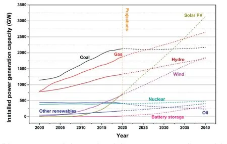
Fig.1.Installed power generation capacity by the source in the stated policies scenario 2000–2040 in“World Energy Outlook 2019”[2].
To bring MWEHs into a range of application,their performance needs to be constantly improved to meet the increasing demand from the loading applications.Since most application scenarios of a MWEH have restricted space,there is often a lack of high wind speed.
The average wind speed in an urban area is mainly within the range of 1 m/s to 7 m/s(Fig.2).Hence,a design to be able to effectively convert the kinetic energy of low-speed ambient wind into electric energy is crucial.Overall,a broadband/large-speed-range capability is preferred while an unstable wind-speed and variety of wind direction are to be expected from ambient wind.Another important criterion is reliability.In most cases MWEHs are used to replace a battery-powered solution,and the reliability of MWEHs will directly determine thefinal product life-cycle.In addition the ability to be able to manufacture the MWEHs plays a major role in terms of usage in many applications.The capability of large-scale manufacturing and a simplified assembly process would be big advantages.
2.Fundamentals of MWEHs
The energy conversion process of an MWEH consists mainly of two parts:fluid-solid coupling and electromechanical conversion(Fig.3).According to the different fluid-solid coupling mechanisms,MWEHs can be divided into rotating wind energy harvesters and wind-induced vibration energy harvesters.
The principle of commercializing a rotating wind energy harvester isfirst to convert the incoming flow blows into the rotation of a wind turbine through its paddle structure,thereby transforming the flow's kinetic energy into mechanical energy.Following that,the mechanical energy is converted into electrical energy through various electromechanical conversion mechanisms for energy supply.Rotating miniature wind energy harvesters have many drawbacks,such as complicated manufacturing process,low collection efficiency due to a large amount of domain air drag,and serious bearing loss.
The wind-induced vibration miniature wind energy harvester is designed to let wind blow over a specifically designed structure to cause mechanical vibration.Therefore,the flow's kinetic energy isfirst converted into vibration energy.The vibration energy is then converted into electrical energy by an electromechanical conversion mechanism.Because of its simplicity and large-scale manufacturing feasibility,the miniature wind-induced vibration energy harvester has become the research focus in recent years.
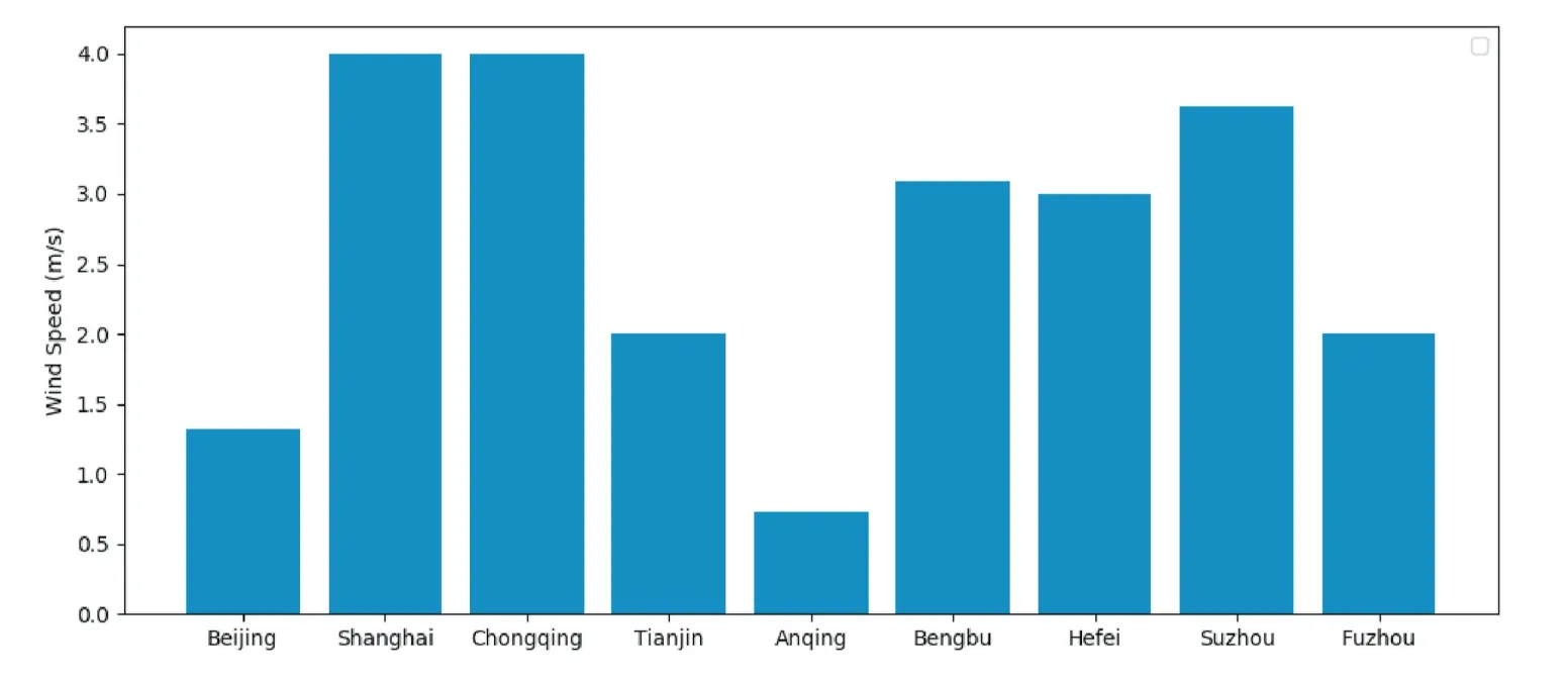
Fig.2.Wind speed in major Chinese cites(data from local weather forecast)
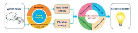
Fig.3.The energy conversion process of miniature wind energy harvesters.
2.1.Energy coupling mechanism
2.1.1.Wind-induced rotation
Wind turbines have played a significant role in renewable energy sources since the early 1980s.The commercialized wind turbine has been optimized through many iterations with many tricks to improve the working efficiency[3–7].However,when the dimension of the complete system is further reduced into the centimeter/millimeter range,it is very rare tofind a commercialized turbine with an optimal design.
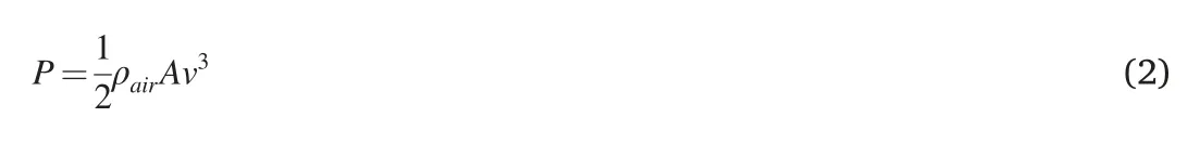
In general,a wind turbine consists of three major components:a rotor,a generator,and a structural support component.During operation,the kinetic energy of the incoming wind is captured and transformed into mechanical rotation energy by rotation of the rotor.According to the kinetic power equation,the total available kinetic power from the incoming wind is:

wheremis the mass of air blown over the wind turbine andvis the speed of the incoming wind.By using the swept area of the wind turbine rotor(A)and the density of air(ρair)to replace the mass of air(m),the above equation can be rewritten as:
The wind turbine is usually not designed to completely block the air flow.Thus the potential power which can be obtained through can be expressed as the kinetic power difference before and after reaching the rotor.
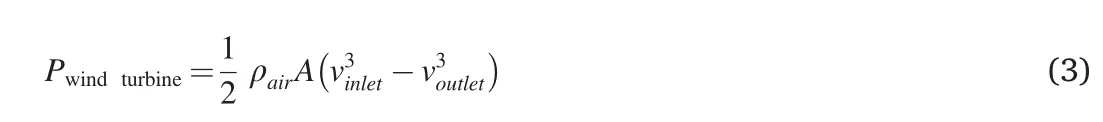
If the mass of air is kept constant,Eq.(3)can be rewritten as:
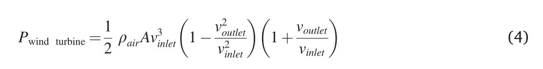
Given a numeric solution of Eq.(4),the maximum potential power of a wind turbine is
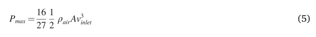
which is known as the Betz limit.
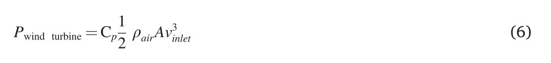
To analyze the efficiency of various wind turbine designs,the power coefficient of the rotorCp(θ,λ)has been introduced(note that this is also called‘aerodynamic efficiency’in some articles).It is a function of turbine blade pitch angleθand tip speed ratioλ,and feature a nonlinearity.The pitch angle is defined as the angle between the surface of blades and the plane of rotation.
The tip speed ratio can be obtained from the speed of the turbine blade in a tangential direction divided by the incoming wind speed.
ωis the angular velocity of the rotor and r is the radius of the blade.
Following the Betz limit,a theoretical maximum power coefficient of around 59.26%is expected for a perfectly ideal turbine blade.However,according to Gasch and Twele[8],the theoretical maximum power coefficient of a state-of-the-art miniature wind energy harvester is only 40%at lower-operating Reynolds numbers(Re<105).
Both Slootweg[9],Borowy and Salameh[10],and Salameh[11]propose that the power coefficient,Cp(λ,θ)can be approximated as
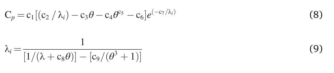
where c1-c9are power coefficients.Xu[12]suggests a list of power coefficients based on a approximation curvefit from experiment data(Table 1).Consequently,with the given blade size and wind velocity,the wind turbine power coefficient can be optimized through the pitch angle θ.
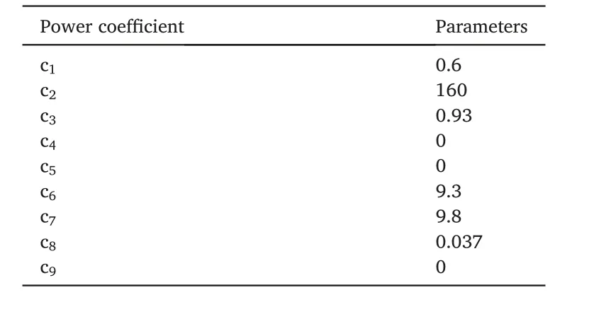
Table 1 The parameters of the approximated power coefficient suggested in Xu[12].
In recent years,studies on cm-scale wind turbine design have been increasing because of the increase in IoT applications.Various methods including a ducted-turbine design to optimize blade aerodynamics have been systematically investigated.
Unfortunately,the viscous drag on the blades at low Reynolds numbers cannot be ignored and plays a pronounced role in thefinal conversion efficiency.The bearing losses also become notable when the scale of the system is reduced into the cm range.The scale effect caused by efficiency decay is rather significant with a conventional turbine design.
2.1.2.Wind-induced vibration
As an alternative to a rotation mechanism,the wind-induced vibration method transforms the air flowfirst into vibration on the electromechanical conversion structure instead of rotation of a rotor.Therefore,the bearing in the wind turbine rotor has been avoided.Consequently,the friction losses due to the miniature bearing are completely removed.Furthermore,unlike the turbine blade design,the Wind-induced vibration mechanism usually uses a combination of fluidic lift and drag to convert the flow energy.This makes the wind-induced vibration more suitable for low wind velocity applications in the sub-cm size range.Importantly,for a device in the cm size range,vibration on the structure is much more easily converted into electrical energy than with rotation.This makes using various electromechanical conversion mechanisms possible.With all the mentioned advantages,wind-induced vibration has been widely studied for the cm size wind energy harvester.This mechanism could be further cataloged into three major categories based on the air dynamic phenomenon:vortex-induced vibration(VIV),aero-elastic flutter,and galloping.
2.1.2.1.Vortex-induced vibration(VIV).Vortex-induced Vibration is one of the most common phenomena in nature.It is well known in thefield of civil engineering,where it can produce enormous energy sufficient to destroy large buildings include the Tacoma Narrows Bridge and the Ferrybridge cooling tower.However,in thefield of EH design,vibrational energy generated by wind flow in the ambient environment can also be converted into electricity with an appropriate conversion method.This method features compact dimension and reasonable energy density as well as good reliability.Overall,the VIV wind energy harvester has significant advantages thanks to its tunable performance and simplicity.
The VIVs are strongly dependent on flow velocity and bluff body geometry.When flows cross a bluff body,the vortices start to form in its wake.Following the increasing flow velocity,vortices periodically shed and travel into the downstream to form a vortex street(see Fig.4).The shedding frequency f of the vortex is defined as:
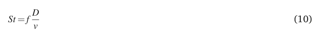
where the Strouhal numberStis a constant within a given Reynolds number range(for 300<Re<1.5×10⁵,Stis approximated as 0.2),vis the flow velocity andDis the characteristic length of the bluff body.The vortex shed on the surface of the bluff body will generate an alternating pressurefield which leads to a vibration of bluff body structure.The fluid kinetic energy can be harvested through the vibration of the bluff body and an appropriate energy conversion method.To maximize the conversion efficiency,resonance of bluff body is needed.This will occur when the vortex shedding frequency and eigenfrequency of the bluff body are matched.Therefore,the forced oscillation on the bluff body needs to be reviewed to obtain an optimized structure.

Eq[11].is the structural oscillation equation,wherem,c,kare mass,damping,stiffness of the vibration system respectively.The massmtakes into account both the mass of the bluff bodymsas well as the mass from fluidmf,which models inviscid inertial effects.
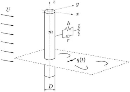
Fig.4.The schematic of the coupled oscillator model for 2-D vortex-induced vibrations[13].

whereρis the density of fluid,Cmdenotes the added mass coefficient and μrepresents a dimensionless mass ratio.
The dampingcincludes both viscous dissipation in thefixturecsand the additional damping from fluidcf.

whereωis the eigenfrequency of the bluff body structure in air,andγis the function of vibration amplitude.
Naturally,the VIV coupling method will reach its maximum efficiency when the vortices shedding frequency is matching the eigenfrequency of the oscillator structure.This is called the lock-in condition.Once the electromechanical conversion mechanism has been chosen the frequency matching can be easily carried out by changing the dimension of the bluff body.This leaves a relatively large amount of leeway for later electromechanical conversion structure design.
Hartlen and Currie[14]suggested that the action forcesFfreceived on the bluff body are mainly contributed by the fluctuating lift force.It can be expressed with dimensional variables as:
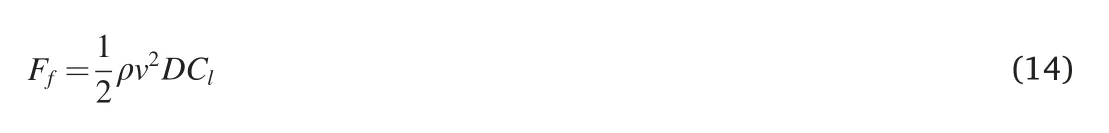
It is worth mentioning thatCLdoes not correspond to the total instantaneous sectional lift coefficient on the bluff body structure,whileFfrepresents the force caused only by vorticity in the wake.This indicates that the VIV action forces also can be at a maximum during the optimization process by using variation in the bluff body shape.In some articles,even an aerofoil-shaped bluff body could be employed to further improve the wind-induced action forces.
Another potential method is to use the alternating pressurefield in the bluff body's weak region to form a forced vibration on a specially designed resonator(see Fig.5).Therefore,action forcesFfcan be approximated as the pressure difference between upside and downside vortices in the weak region as:
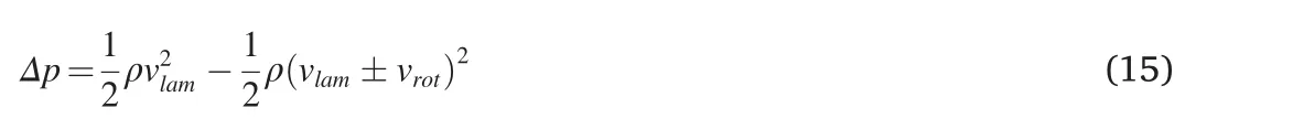
where thevlamdenotes the flow velocity of laminar flow in the downstream,andvrotis the rotational velocity from the vortex motion,which strongly depends on the bluff body.As proposed in Ref.[16],the rotational velocity of vortices in the bluff body weak range is mainly caused by a drag force acting on air-flow from the air passing around the bluff body.The drag takes two forms,friction and form drag.Friction drag will lead to kinetic energy loss on the surface of the bluff body rather than in the weak region.It should be minimized during the optimization process.The form drag needs to be enhanced since it mainly transforms laminar air-flow into vortices in the weak region.As a result,the driving pressure in the bluff body weak region could be maximized by using an optimized bluff body.
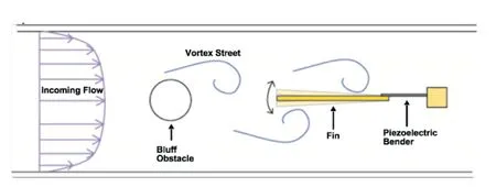
Fig.5.Diagram illustrating the use of the bluff body's weak region for the VIV coupling mechanism[15].
Compared with other wind-induced vibration phenomena,VIV has a great advantage in being well understood from extensive study of its hydrodynamics.The working principle of VIV is well explained,which leads to a relatively established performance tuning/optimization method.With an appropriate energy conversion mechanism,the VIVbased wind energy harvester can deliver a very reasonable/high power conversion efficiency at a relatively low flow velocity.The only drawback of the VIV method is its narrowly-optimized working incoming velocity range.This limits its usage in some applications.
2.1.2.2.Aero-elasticflutter.Flutter is an aeroelastic instability phenomenon involving both the bend and twist motion.Structural vibration appears when the structure experiences an aerodynamic force with a phase difference.During flutter,the flow energy isabsorbed by the vibrated systems while negative damping can occur during the vibration.As fluidic energy has been absorbed by the vibration system,the amplitude of vibrations increases continuously and leads to a divergence in the case where the aerodynamic damping is greater than the mechanical damping.It has been proved that the flutter is a self-excited and self-sustaining phenomenon that shows a strong dependence on the length and stiffness of the structure[17].Studies have been extended in Ref.[18].The relationship between flutter frequency,critical flutter speed,and other system parameters are systematically investigated,and scaling laws are developed for two-dimensional compliant beams in viscous flow.
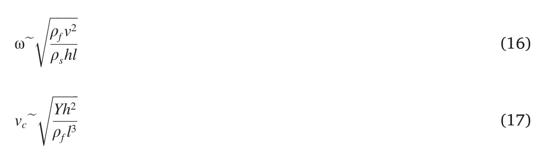
where the flutter frequency isω,vcrepresent the critical flutter speed,andρf,ρsare the fluid and structure densities respectively.vis the flow speed,his the cantilever thickness,L is the cantilever length,andYis the beam elastic modulus.It is proposed in Refs.[19,20],that the flutter is a combination of in vacuo mode(thefirst and second modes usually)shapes if the non-dimensional mass ratio(defined as in Eq.(18))is relatively large.
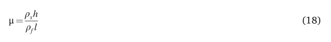
Based on[21],when a small mass ratio appears,the beam's flutter motions were mainly dependent on additional mass from fluid and viscous effects instead of predicted modal displacements.
In terms of high-incoming wind speed conditions,the flutter-based energy harvester has great potential thanks to its large vibration amplitudes.The characteristic of self-excitation and divergence appears also to be very good for highly varied wind velocity conditions.However,since the aero-flutter falls into the category of a chaoticfield,numerical analysis,and further model-based optimization would be very beneficial but studies on this are yet to appear in the literature.
2.1.2.3.Galloping.Galloping is a phenomenon of self-excited vibrations caused by aeroelastic instability,which is related to the velocity of the flow and the relative orientation of the structure to the flow.It is usually characterized by low vibration frequency and high vibration amplitude.In some practical cases,it is very close to the combination of direct and weak VIV coupling on the same structure.The model of a typical galloping energy harvester with SDOF(single degree of freedom)is illustrated in Fig.6,while the corresponding equation is similar to Eq(1).However,unlike the previous analysis for VIV,the fluid action force is determined as:
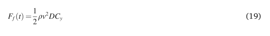
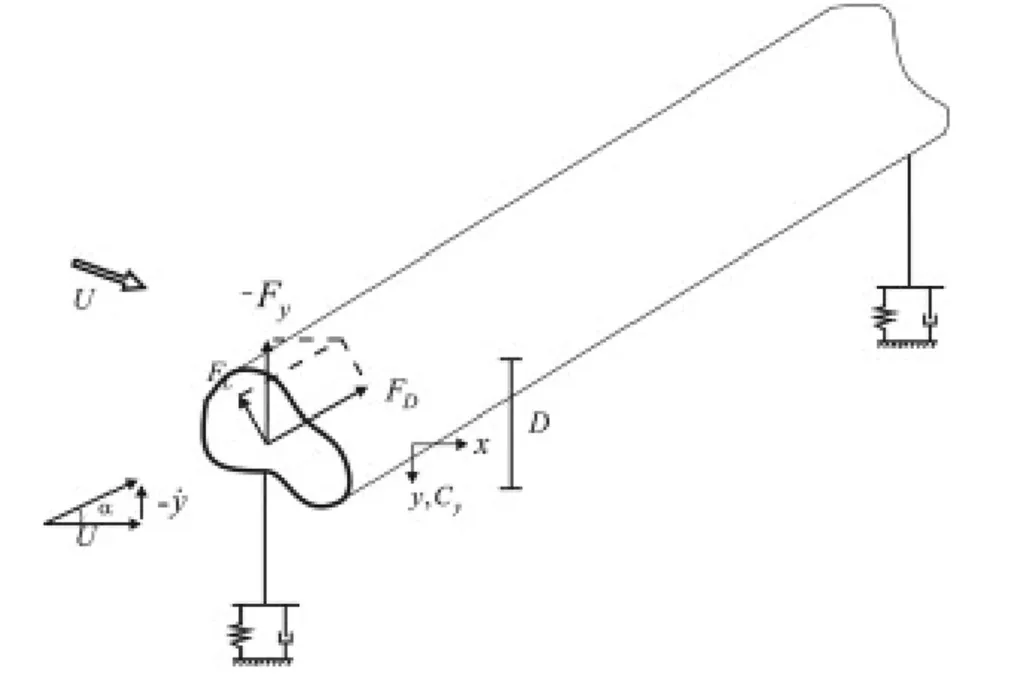
Fig.6.Schematic of the galloping coupling mechanism[22].
Usually,the transverse galloping phenomenon is characterized by a timescale of the body oscillation(~2π/ωN)much larger than the characteristic timescale of the flow(~D/v).Therefore,the fluid forceFf(t)can be evaluated by using the quasi-steady hypothesis.Hence,the fluid forceFf(t)can be expressed as a 3rd order polynomial expansion of the angle of attack.Consequently,Cyis related to the lift and drag coefficientsCLandCD[22].
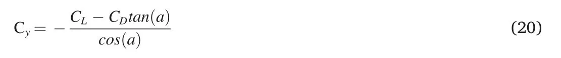
Hence,the fluid action force given in Eq.(19)could be approximated as:
where a1and a2are empirical coefficients,which can be obtained through applied polynomialfit theCyversustan(a).Both coefficientsa1anda2show a dependence on cross-section geometry,the aspect ratio of the body(L/D),and the characteristics of the incident flow.However,a1anda2are independent of the Reynolds number.The angle of attackαcan be expressed as:

Note that the aerodynamic force on the square column is the nonlinear element,so the damping term in the galloping model can be expressed as the sum of a linear damping()with a nonlinear damping().Thus the damping coefficient form is
For the galloping energy harvester,the linear damping term determines the lowest wind speed.Galloping energy harvesting can be achieved at a relatively low working speed by adjusting the structural parameters of the oscillator and the shape of the bluff body.The output energy efficiency increases following the increase of wind speed.The nonlinear damping term has a great in fluence on the maximum amplitude of the harvester.It also provides a vibration mitigation effect to ensure a stable vibration and a suitable working wind speed range.
3.Research status of MWEHs
3.1.Rotating wind energy harvester
As mentioned earlier,the rotating wind energy harvester is mainly composed of two parts:a stator and a rotor,where the blades of the rotor have a certain inclination.It has played a significant role in renewable energy since the early 1980s and has experienced countless improvements.The need for a cm-scale rotating wind energy harvester has been discussed very often in recent years with the increasing number of IoT applications.
Howey[23]proposed a miniature rotating shrouded wind energy harvester,which has a rotor diameter of 2 cm.With a 3.2 cm outer diameter,it can generate electrical power by the axial-flux permanent magnet machine placed in the shroud(Fig.7 a).The stator of the generator is fabricated by a combination of both milling machine,3D printing,and flexible printed circuit board technology.A jewel bearing has been employed to reduce the friction and ensure a low start-up speed.The demonstrator could operate at an air velocity down to 3 m/s.Electrical power between 80μWand 2.5 mWcould be expected at airspeeds in the range of 3–7 m/s.Due to the size of the components,the fabrication and assembly process is much more complicated than larger size commercialized wind turbines.
Fang[24]designed a simple but very efficient wind energy harvester that could be easily manufactured.It moves the air outlet to the top side(Fig.7 b).The centrifugal-fan-like design successfully enhances the rotation stability of the blades and effectively increases the rotational speed of the turbine.Fang has proved that this design effectively improves output performance.As demonstrated,it can generate a maximum output power of 40.7 mW at 15 m/s wind speed.
For turbine aerodynamic performance optimization,Wu [25]designed an electromagnetic rotating windmill-like energy harvester with dimensions of 75 mm×60 mm×30 mm.Various windmill structures were designed and verified by simulation tofind an optimal structure which would ensure the highest aerodynamic efficiency.A demonstrator has been fabricated and experimentally characterized.The experimental results compare the effects of 7 different rotor shapes on output performance.The harvester with the fourth rotor(as shown in Fig.7 c)has the best output performance.Under the excitation of 3 m/s wind,the average output power is 3 mW.
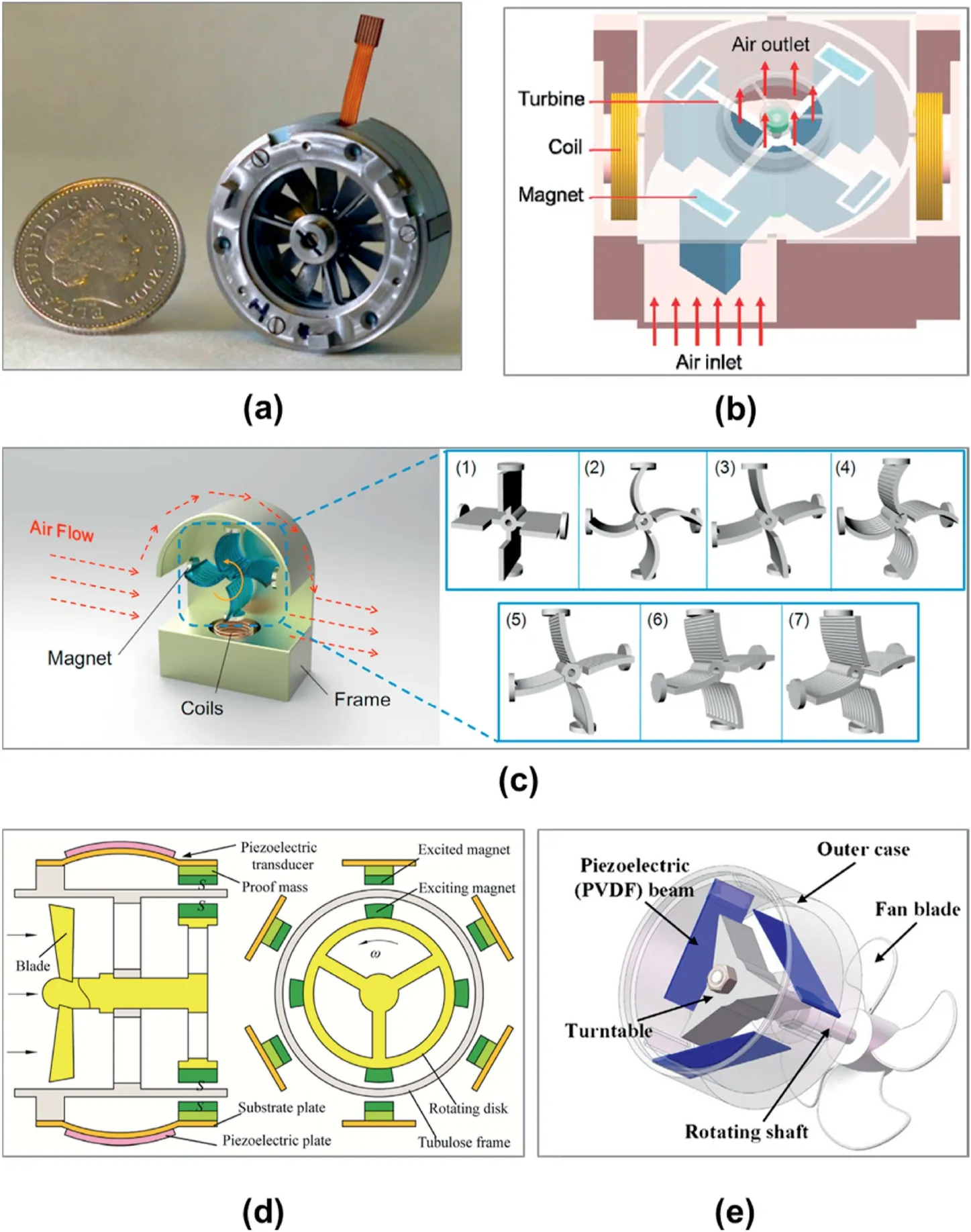
Fig.7.Structures of various rotating wind energy harvesters.(a)Miniature rotation-based wind energy harvester proposed by Howey et al.[23]with axial-flux magnet placed in the shroud;(b)a centrifugal-fan-like rotation wind energy harvester[24];(c)Windmill-liked rotating wind energy harvester with 7 different rotor shapes[25];(d)Piezo-windmill designed for low speed and wide range application[26];(e)Rotational energy harvester based on a PVDF beam[27].
The lower efficiency of the cm-scale wind turbine is not only because of the low performance of the coupling structure design at a miniature dimension,but also because of the electromechanical conversion mechanism[3].Recent articles also compared the performance of an MWEH using the piezoelectric conversion principle with the traditional electromagnetic principle.
Kan[26]proposed a piezo-windmill that utilized a rotating magnet to convert energy from a broad wind speed range at low velocity.The piezoelectric cantilever beam of the device is located on the stator.The free-end of the cantilever beam and the rotor are equipped with magnets(Fig.7 e).When the rotor rotates,the magnets on the piezoelectric cantilever beam will receive the periodic repulsive force of the magnets on the rotor,and this will deform the piezoelectric sheet.Experiments show that when 6 magnets are installed on the rotor,a maximum voltage of 37.2Vcan be reached under the excitation of 6 m/s wind speed.
Zhang[27]also presents a rotational piezoelectric energy harvester that could efficiently harvest wind energy at a much higher wind speed.Methods to improve a harvester performance by PVDF beam vibration frequency adjustment have been proposed.A demonstrator proves it can effectively convert wind energy and that a maximum RMS voltage of 160.2Vcan be obtained at 14 m/s wind speed,with the maximum output power reaching 2566.4W.
3.2.Wind-induced vibration energy harvester
The miniature wind-induced vibration energy harvester converts wind energy into vibration energy using vortices,gallop,flutter,and wake gallop.It has a generally high energy density while it avoiding bearing loss completely and is suitable for low Reynold number.Thanks to its simple structure,it also features easy integration with the standard micro-electromechanical fabrication process.The common feature of this type of wind energy harvester is that only when the wind velocity exceeds a certain value(critical wind velocity),the harvester can produce a higher electrical output.Compared with vortex vibration piezoelectric wind energy harvesters,galloping and flutter piezoelectric wind energy harvesters have higher electrical output,but the starting wind speed is often higher.However,flutter wind energy harvesters have shown a clear advantage in highly variable wind speed applications because of their higher bandwidth.
3.2.1.Vortex-induced vibration(VIV)
As discussed in section 2,vortex excitation is a fluid-solid coupling phenomenon often involved with a bluff body.The typical bluff body shape is a cylinder.When the fluid flows through the bluff body,it will form periodic vortex shedding behind the bluff body(Kamen vortex street).An alternating up and down aerodynamic force is produced on the surface of the bluff body.If the bluff body is elastically supported or there is an elastic structure in the wake of bluff body,and its natural frequency is similar to the vortex shedding frequency,a vortex-induced resonance phenomenon with enhanced amplitude will occur.At the same time,it is accompanied by a frequency lock-in effect(see Fig.8).
Most published wind-induced vibration energy harvesters are based on the vortex-induced effect and have a piezoelectric cantilever beam structure.Wang[28]reported a piezoelectric wind energy harvester that has a modified bluff body shape.A pair of Y-shaped attachments have been used to enhance the performance of the harvester.The results of this improvement,vibration amplitude,and frequency,are analyzed with the Lattice-Boltzmann CFD method.
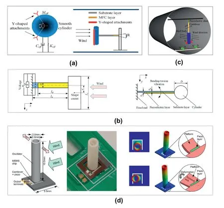
Fig.8.Structures of various VIV-based wind energy harvesters.(a)VIV-based piezoelectric energy harvester with Y-shaped attachments on the bluff body[28];(b)An asymmetric VIV-based harvester design for lower operational wind speed[29];(c)A Tri-stable VIV harvester from Zhou et al.[31];(d)MEMS wind energy harvester with cylindrical design by Lee et al.[32].
A novel asymmetric piezoelectric harvester design was developed by Jia[29]to capture wind energy at a much lower wind speed.It could handle both bending and torsional vibration caused by vortex-induced vibration.It featured a lower natural frequency and a smaller electromechanical coefficient than the conventional vortex-induced piezoelectric energy harvester while the asymmetric configuration contributes to a lower wind speed.Therefore,it has the advantage of generating more power at low wind speed than a conventional symmetric design.Jia also suggests the natural frequency and optimal wind velocity could be further lowered by increasing the length of the cylinder and eccentric distance if needed in practical application.
A 2-DOF piezoelectric vortex-induced vibrations energy harvester is proposed by Sun[30].It consists of an outer beam,an inner beam,a cylinder,and tip masses attached to the piezo-beam.Thefirst two resonant models of the structure have been designed to close,by attaching the inner beam directly to the free end of the outer beam.This 2-DOF harvester is designed to operate in the working wind speed range even when it is beyond the lock-in speed/frequency.Thanks to this design,it not only featured an increased operation wind speed range but achieves higher voltage than the 1-DOF counterpart at both low speed and high speed.
Zhou[31]presents a vortex-induced vibration energy harvester design which could further increase the operating wind speed range.As discussed in this article,Zhou successfully realized a tri-stable configuration using magnetic force.The demonstrator shows an excellent broadband energy harvesting performance at low frequency under low-level excitations.
Lee[32]reports an MEMS vortex-induced vibration wind energy harvester design where a cylindrical oscillator is attached to a piezoelectric silicon chip.The power output of the reported demonstrator is in the nanowatt range.Thanks to its compact size,it can be arranged into an array formation,which could bring a noticeably improved power output.
A vortex-induced vibration-based MWEHgenerally has lower applied wind speeds.However,this type of energy harvester only obtains energy within a certain wind speed range given the characteristic of the VIV phenomenon.The current study is focused on the maximum fluid action forces as well as improved the operational wind speed range of a VIVbased MWEH.
3.2.2.Galloping
Galloping generally occurs in light,non-streamlined bluff structures with edges and corners(rectangular,triangular,"D"-shaped cross-section,etc.)which can generate a periodic aerodynamic force from the change in relative wind attack angle.The attack angle changes by structural motion and gives a quasi-steady aerodynamic force.As introduced in section 2,the damping of the galloping system is designed to be negative,but it often does not diverge thanks to its non-linear damping.
Shi[33]demonstrated a miniature galloping-based zero-powered wind velocity sensor which has a simple,low-cost construction(see Fig.10).A prismatic bluff body with a triangular cross-section is attached to the free end of a polyvinylidene fluoride cantilever.The bluff body vibrates under a wind excitation because of the galloping effect.The piezoelectric cantilever converts the vibration into an electrical signal/-energy.The system is designed for a wind velocity from 4.45 to 10 m/s without an additional power supply.It is noted that the structure has a negative correlation between wind speed and vibration frequency.

Fig.9.Structures of various flutter wind energy harvesters.(a)Electromagnetic flutter-based energy harvester from Humdinger[39];(b)Flutter-based harvester with an“inverted”orientated cantilever[40];(c)Flutter-based harvester with a TENGs membrane sandwiched between parallel counter plate electrodes[41];(d)Flutter-based harvester employing a Kaptonfilm and Cu as triboelectric nanogenerator[42];(e)Flutter-based harvester with venturi design and triboelectric conversion mechanism[43];(f)A double-flag-like fluttering energy harvester with a triboelectric conversion mechanism[44].
As an alternative to the piezoelectric conversion method,Lai[34]proposed a novel galloping wind energy harvester,which has a cuboid bluff body and an integrated vibro-impact dielectric elastomer generator.The dielectric elastomer generator was used to transform the vibration energy into electric power.
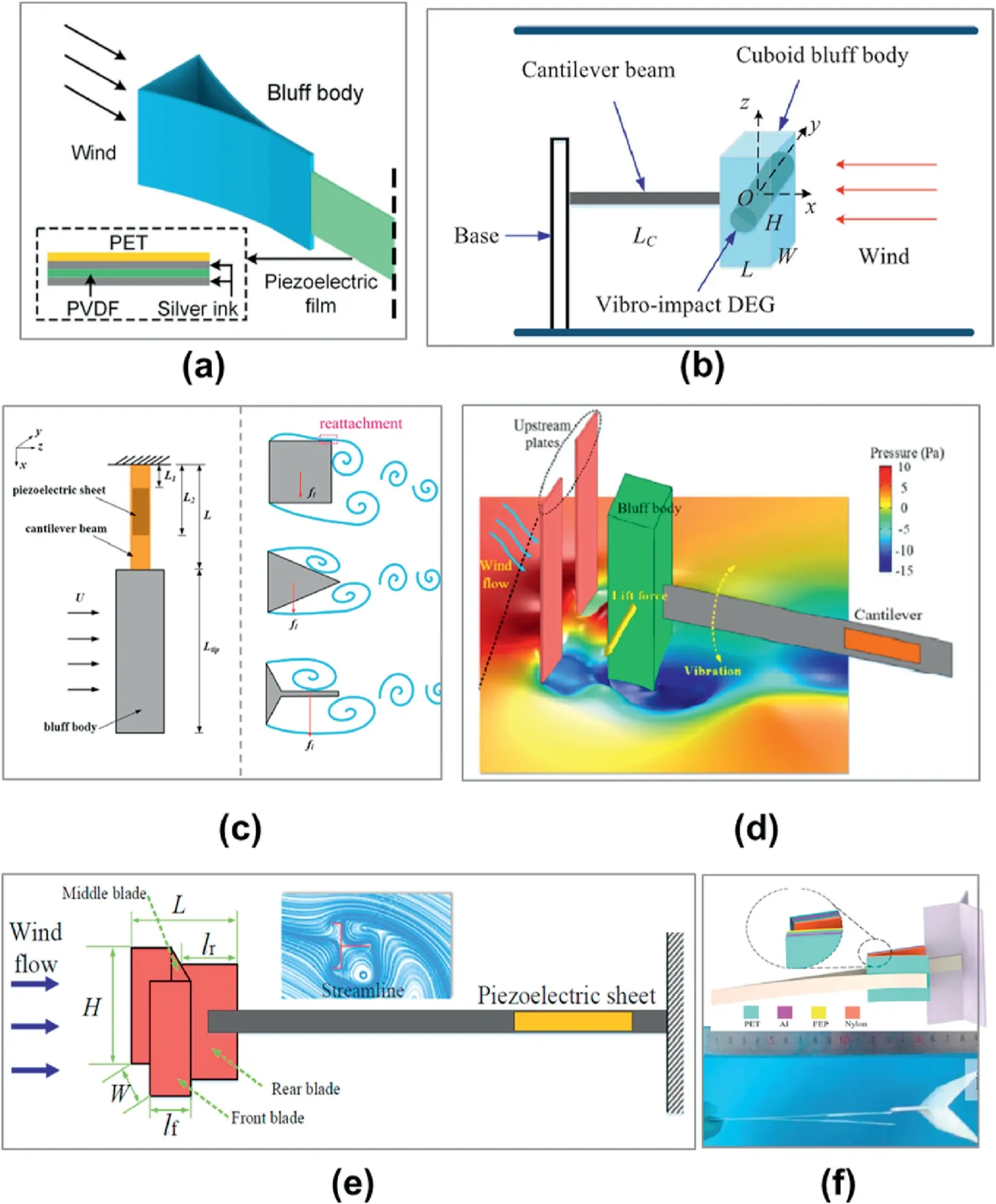
Fig.10.Structures of various galloping wind energy harvesters. (a) Single-degree-of-freedom galloping harvester with the prismatic bluff body[33];(b)Galloping-based harvester consisting of a cuboid bluff body,a cantilever beam,and a Vibro-impact dielectric elastomer generator in the bluff body[34];(c)Funnel-shaped galloping energy harvester optimized for wide operational wind-speed range [35];(d) Galloping energy harvester with a double-plate placed upstream to generate the desired attack angle[36];(e)Galloping piezoelectric energy harvesting consisting of a fork-shaped bluff body[37];(f)Galloping triboelectric nanogenerator based on contact electrification[38].
Like the VIV coupling method,the conversion efficiency of a galloping-based wind energy harvester can be improved by optimizing the fluidic dynamic configuration of an MWEH.Thus,studies have explored reducing the operational wind speed and enhancing the fluid action force by optimizing the shape of the bluff body or introducing other additional fluid dynamic structures.
A funnel-shaped galloping energy harvester was presented by Zhao[35].This is optimized to feature a wide operational wind-speed range and high normalized harvesting power.A funnel-shaped bluff body is used to avoid vortex reattachment.This leads to an enhancement of the structural non-stream fluid flow and allows pressure direction to be along with the lift force.Consequently,the energy harvesting efficiency can be improved thanks to the enlarged aerodynamic force.The performance of three different shape bluff bodies i.e.square,triangular,and funnel,are discussed.Results show that the maximum power densities for the funnel,triangle,and square-shaped bluff bodies are 2.34 mW/cm3,1.56 mW/cm3,and 0.207 mW/cm3respectively.The corresponding onset galloping wind speeds are 7 m/s,9 m/s,and 13 m/s.As the result suggests,the funnel-shaped bluff body design delivers the highest power density at the lowest speed.It also shows a very promising normalized power density compared with the common square-shaped design.
Liu[36]suggests placing a double-plate structure upstream of the blu ff body.Results demonstrated that this configuration change can lead to a significant improvement in the MWEH performance.At a certain wind speed,two wake flow zones with low-pressure are formed behind two upstream plates.This induces the blu ff body at the downstream(intermediate position)to deviate to both sides.As a result,even at low wind speed,the vibration of the blu ff body at a reasonable amplitude can still occur because the pressure fluctuation of the wake zone disturbs the static equilibrium.Placing the double plates upstream of a wind energy harvester also changes the vibration response from vortex-induced vibration to galloping,while the wake from the double plate also results in an attack angle changing on the original bluff body.When the ratios of the horizontal and vertical distances to the windward width of the cylinder are 1 and 0.5,respectively,the cut-in wind speed is successfully reduced to as low as 1.5 m/s.For the galloping-based wind energy harvester with a square prism,after the double plates are placed upstream,the cut-in wind speed decreases from 3.5 m/s to 1 m/s,and the output voltage increases from 1Vto 12Vat 1.5 m/s.The increase of voltage caused by the addition of double plates upstream of six di ff erent blu ff bodies indicates the good adaptability of this kind of fluidic configuration.
A galloping piezoelectric energy harvesting with a fork-shaped bluff body is proposed by Zhang[37].The results from this suggest that the fork-shaped design can generate much higher output voltages than previous triangular-shaped and square-shaped bluff bodies.The article points out that the best harvesting performance of the fork-shaped bluff body appeared when the ratio of the front blade length to the bluff body width was 1/4.The energy harvesting efficiency could be improved in a wider blade length ratio(0.75~1)if cover plates have been added on two ends of the bluff body.
Recently,the discovery of the triboelectric nanogenerator opens a new option for the galloping-based MWEH design.The triboelectric nanogenerator can be made of polymer,which is relatively easy to mass produce.Because of its natural characteristics,it usually offers a remarkably high voltage output,which has been considered as an advantage for power management circuit design.The low reaction forces from the triboelectric conversion mechanism also ensured its performance at lower wind speeds.
A galloping-based triboelectric nanogenerator(GTENG)is introduced by Zhang[38]which has a significant advantage when used with low wind speeds.The impact behavior occurs between the main beam and the auxiliary flexible beams in the case of the bluff body subjected to cross flows beyond the critical wind speed.The vibration energy has been scavenged thuscontact electrification between two flexible beams.Both the coupled interaction between the two beams and different contact modes have been investigated.Zhang proposed a theoretical model to reveal the working mechanism and oscillating behaviors of the GTENG.With the GTENG design a 3 cm×3 cm TENG cell could deliver over 200Voutput voltage under 1.4 m/s wind.The average output power at 1.4 m/s can reach 60%of that at a relatively high wind speed of 6 m/s.
Compared with the wind-induced vibration energy harvester based on vortex-induced vibration,the galloping-based system can obtain energy over a wider wind speed range with a higher power density.Overall,from the literature,galloping clearly offers an advantage in most application conditions.
3.2.3.Aero-elastic fl utter
Like gallop,the flutter phenomenon also comes from negative damping.Unlike gallop,flutter generally occurs in sheet-like structures(such as flat plates,membranes,wing-shaped structures,etc.),and its aerodynamic force is often chaotic(see Fig.9).Flutter-based wind energy harvesters often have larger sizes or higher application wind speeds.However,because of the absence of bluff bodies and the divergence of flutter,the power density of such energy harvesters is generally very high.
The Humdinger Wind Energy Company invented an electromagnetic wind-induced vibration energy harvester.The device is mainly composed of four parts:a double-ended flexible beam,two magnets,one or more coils,and a shell.Franye produced two prototypes with lengths of 12 cm and 1mrespectively and claimed that this energy harvester can be used to solve the power supply problem of the island in question.Aquino[39]investigated the performance of the device under the effect of various wind speeds and mounting locations.The result gives an insight into the potential of integrating the harvester into a smart infrastructure/building.The flutter energy harvester was able to produce 8.72Vpeak-to-peak voltage.A 1 mA short-circuit current could be reached when the system is subjected to the air flow with 2.3 m/s inlet speed.
Orrego[41]designed a flutter energy harvesting device which consists of a flexible piezoelectric membranefixed in a novel orientation called the“inverted-flag-like”.A 5.0 mW/cm3peak electrical power could be achieved at under a 9 m/s wind speed.The devices could produce about 0.4 mW/cm3power in a low-wind speed range(~3.5 m/s).This is suitable for more ambient wind conditions.
The triboelectric conversion mechanism shows its excellent performance in thefield of the flutter-based wind-induced vibration energy harvester.Phan[40]reported a new approach to design air flow-driven TENGs.A fluttering-membrane is sandwiched between a pair of parallel counter plate electrodes.The dynamic mechanical interactions induced by air flow over the flexible membrane is converted through triboelectricity.The flutter membrane includes a thin,free-standing aluminum foil electrode covered on both sides with electrospun poly(vinyl chloride)nanofiber-structured mats.The mats are specifically designed to increase the friction area.With this configuration,one single device can produce a 0.33μW peak power in mild air flow conditions.This configuration can be easily scaled up by stacking multiple devices to form a multi-layer construction to obtain a higher power output performance.
Wang[42]reported a wind-powered triboelectric nanogenerator based on contact electrification.It consists of a Kaptonfilm and two Cu electrodes on each side of it.The Kaptonfilm isfixed at both ends in an acrylic fluid channel.The study systematically investigated the relationship between output power density and fluid channel dimensions.A fluid channel which has a size of 125×10×1.6 mm3could deliver 9 kW/m3maximum output power density under a 2.3 MΩloading resistance.
Ravichandran[43]designed a triboelectric wind nanogenerator based on a 3D printed venturi design system.The device is relatively simple and compact.However,with appropriate optimization,it could produce a 1.5 mW average power(peak power output of 4.5 mW).The device's maximum output power density could reach 2850 mW/m2,which is much better than those achieved in studies that use a larger surface area at higher wind velocity.
Sun[44]proposed a double-flag triboelectric nanogenerator for wireless sensor network nodes.It consists of two thin fluorinated ethylene propylenefilms that have evaporated Ag electrodes covering the surface.Those twofilms werefixed back-to-back with a certain gap.A fully flexible TENG with a contact separation mode is formed when there is flutter contact between the twofilms under ambient wind.The demonstrator is characterized at different wind speeds.The in fluence of different design parameters,including the material used,sizes of the flags,and gap length between two flags on the peak-to-peak power and RMS power were discussed.As Sun demonstrated the 110 mm×60 mm flag design could reach 600 mW/m2peak-to-peak power density,with an RMS power density of 10 mW/m2.
4.Performance enhancement technologies of MWEHs
4.1.Structure optimization and new confi guration proposal
Thanks to the nature of the wind-induced vibration coupling mechanism,the most straightforward method to improve the performance of MWEH is by introducing an array design(see Fig.11).
Kwon[45]developed a wind-powered triboelectric energy harvester array.The harvester consists of a flappingfilm array,which is fabricated by plastic deformation of polymerfilm at elevated temperatures.Thefilm forms a curved shape by plastic deformation,and creates a variable gap between the flap and the substrate.The flappingfilm array starts to vibrate when the wind is introduced.The energy is generating while the contact area changes according to the deformation of the flappingfilm.It can convert wind energy at various speeds and directions.This array design could produce an average power of 0.42μWunder 5.8 m/s wind speed.
Array design can effectively increase the output power.However,the power density cannot be improved by simply scaling up the coupling structure.Another practical method to improve the overall power density is to introduce a multi-model coupling structure by employing a multidegree of freedom design.
A two degrees of freedom(DOF)galloping wind harvesters with a nested structure has been reported[46].It comprises outer and inner square-shaped blu ff bodies in tandem.Both blu ff bodies were connected to elastic cantilevered beams separately to allow separate oscillations.The fluid-solid interactions coupling mechanism with two blu ff bodies configuration is analyzed.Power spectral density(PSD)was used to analyze the in fluence of gap distances.The performance of these two degrees harvesters was compared with conventional single-DOF galloping harvester design through wind tunnel tests.The two degrees of freedom(DOF)galloping design shows excellent performance with a power density increase of up to 27.8%.The outer blu ff body has an in fluence on the inner bluff body.At low wind speed,it is the secondary cause of inner body vibration after the plain galloping that is directly induced by the incoming wind.
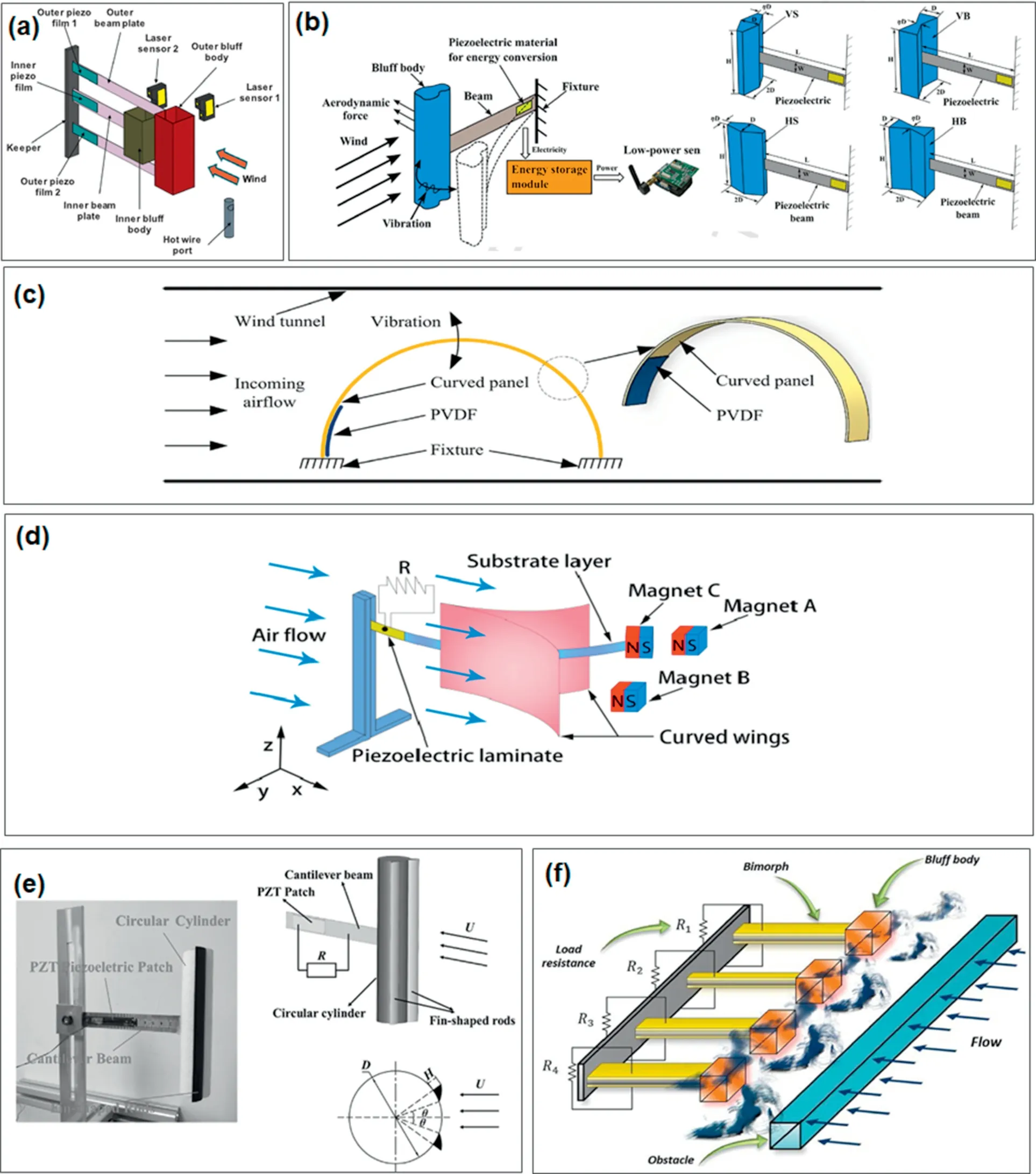
Fig.11.Structures of wind energy harvesters are employed with various performance enhancement modifications.(a)Galloping-based harvester with two degrees of freedom design to enhance the power density[46];(b)Novel spindle-like and butter fly-like bluff bodies and coupling both the vortex-induced vibration and galloping phenomena simultaneously[48];(c)Novel flutter-induced vibration energy harvester with a curved panel for wide operational wind-speed-range[49];(d)Y-shaped bi-stable energy harvester(YBEH)to scavenge low-speed wind energy[50];(e)A piezoelectric aeroelastic energy harvester with a pair offin-shaped rods symmetricallyfixed on the cylindrical bluff body[51];(f)PZT array-based energy harvester design for capturing wind energy in the weak region for a broad range of vortex shedding frequencies[52].
The characteristic of wind under the various application scenarios also needs to be taken into consideration during the harvester optimization stage.
Rezaei-Hosseinabadi[47]presented a wideband piezoelectric wind energy harvesting concept.A design optimization method with the wind speed distribution model in consideration was proposed.The proposed demonstrator was designed to power the wireless sensor nodes in smart monitoring applications.It consists of a piezoelectric beam with permanent magnets(PMs)at the tip and a small turbine with embedded permanent magnets.The vibrations of the piezoelectric beam occurred with a periodicity changed by the magnetic force given by the rotating turbine.The resonance frequency of the beam is designed according to the wind speed distribution model.Compared to the conventional wideband method,it achieves the wideband feature via the arrangement of PMs within the turbine instead of using multiple beams which resonate at different frequencies.As Rezaei-Hosseinabadi suggested,this feature improved the power density of the piezoelectric wind energy harvester.The experiment indicated that the demonstrator has a maximum power density of 0.59 mW/cm3,a maximum efficiency of 24%,and the cut-in wind speed is reduced to 2.1 m/s.
The coupling structure clearly also needs to be modified from the classic cylindrical configuration to obtain an improved output voltage and power density.Research continuously explores and improves the MWEH by introducing novel hydrodynamic design.
Wang[48]proposed spindle-shaped and butter fly-shaped bluff bodies and coupled both the vortex-induced vibration and galloping phenomena to enhance the performance at low wind speed.The results indicate that the performance over a broad range of wind speeds can be enhanced through the vertical installment and small width ratio design.The combination of vertical spindle-shaped bluff body with the smallest width ratio can reduce the cut-in wind speed by over 13%.Compared to a conventional galloping-based energy harvester the maximum voltage output is improved by over 160%.
Shan[49]presented a flutter-induced vibration energy harvester with a curved panel.The in fluence of the air flow velocities,the load resistances,the locating positions and dimensions of piezoelectric patches of polyvinylidene fluoride(PVDF)on the dynamic response and the harvesting performance were discussed.A segmented piezoelectric patches design was preferred because of better harvesting.An output power density of 0.032 mW/cm3is achieved at 25 m/s wind speed with an external load resistance of 10 MΩ.
Zhou[50]proposed a bi-stable energy harvester(YBEH)with a Y-shaped bluff body.This design consists of a cantilever beam with a tip magnet and two curved wings,a piezoelectric laminate,and twofixed magnets.A demonstrator was fabricated and tested over a range of wind velocities.The results suggest it could execute snap-through and reach coherence resonance at a wide range of wind speeds.This opens a new path to use coherence resonance to optimize the energy harvesting performance for low-speed wind.
Ding[51]characterized the performance of a piezoelectric aeroelastic energy harvester with a cylinder-shaped bluff body and a pair of symmetricallyfin-shaped rods.The relation of the circumferential location offin-shaped rods to a harvester's performance is discussed.The test results suggest that,by having optimal angles offin-shaped rods,the synchronization region of the cylinder-shaped bluff body can be expanded.With the 30o-60°configuration,the maximum power can reach 998μWwhich is 25.5 times higher than the unmodified cylinder-shaped configuration.The wind speed range is significantly improved.The demonstrator shows the capability to work with 1.0 m/s wind.Furthermore,it can continuously convert energy when the wind speed is beyond a critical level.
Rezaei[52]presented a PZT energy harvester which is designed to convert energy from a wide range of vortex shedding frequencies with varying wind speeds.An array of bimorphs was located in the wake of a blu ff body.The in fluence of various properties on the lock-in region is investigated along with its power and conversion factor.The results indicate that compared to typical wake-galloping harvesters this design has a wider lock-in region and improved conversion factor.
4.2.Collaboration and coupling enhancement
Along with continuing effort to maximize transformation efficiency by optimizing the hydrodynamic design of the coupling structure,the vibration pick-up structure in the fluid energy coupling mechanism can also be improved.For example,well-designed vibration pick-up structure will be crucial in a VIV-based MWEH while the system can only reach its maximum performance when the fluid shedding frequency is matched with an eigenfrequency of the vibration pick-up structure.The situation is more complicated in the case of flutter-based and galloping-based systems,where both fluid phenomena share the same nature of selfexcited vibration,called broadband excitation capability.By introducing a well-designed vibration pick-up structure,overall system performance can be dramatically improved.To achieve that a non-linearity needs to be introduced into the vibration pick-up structure during the design of the vibration-based MWEH(see Fig.12).
Wang[53]presents a piezoelectric/triboelectric hybrid galloping wind energy harvester.It is designed to cover a range of wind-speed and improve output power at small-scale.The piezoelectric energy harvester(PEH)was designed to start working at low wind speeds.The triboelectric nanogenerators are placed at the boundaries of the vibrational area and cooperate with the PEH at much higher wind speeds.The triboelectric nanogenerator boundaries also function as amplitude constrainers which limit the maximum deformation of the piezo-beam and introduce a non-linearity at higher wind excitation.The hybrid harvester shows an increase in vibration frequency and a better conversion efficiency.A low equivalent stiffness of PEH also secured an improvement at low wind speeds.The dynamic model is established to analyze the behavior of the hybrid piezoelectric–triboelectric wind energy harvester(SHPTWEH).The results show that the boundary design greatly expands the working wind speed range.The total average power output of SHPTWEH was 0.24 mW at 14 m/s wind speed.This was 2.3 times higher than PEH alone.
A dynamic multi-stability wind energy harvester is proposed by Zhou in Ref.[54].A rectangular wing was integrated on a piezoelectric cantilever to initiate the flutter.The multi-stability is realized by a pair of magnets which are oppositely placed on the tip of cantilever and twofixed places.The demonstrator shows a bi-stable characteristic at low wind speed.A tri-stable characteristic could be observed at high wind speed.Because of the dynamic multi-stability design,the piezoelectric cantilever can execute and sustain the snap-through motion over a broad range of wind speeds.The results have shown that it can produce reasonably high output power ranging from 1.5 m/s to 7.5 m/s.
To improve the performance of the wind galloping energy harvester,Hu[55]suggest a piezo-electromagnetic hybrid design.An electromechanically coupled distributed parameter model is established,according to the Hamilton principle,Euler–Bernoulli beam assumptions,a quasi-steady hypothesis,Gauss’law,and Faraday's law.Analytical solutions of the harvester's dynamic response and electric output are given using the harmonic balance method.The result validated the nonlinear results including the Hopf bifurcation and unsteady response.The load resistances are optimized to meet the maximum of the power binary function.The electromagnetic modules show negligible in fluence when the wind speed is smaller than the critical value.It only works concurrently with the piezoelectric modules to realize the hybrid effect when the wind speed exceeds the critical value.Compared to the piezoelectric/electromagnetic galloping energy harvester,it shows excellent performance with an elevated output power for smaller galloping oscillations.
Qin[56]presented a wind harvesting design which uses both vortex-induced vibration and galloping.It consists of a cruciform cantilever beam connected with three bluff bodies(two square,and one cylindrical).Multi-stability was introduced via a tip magnet and twofixed magnets under the excitation of wind.The snap-through motion appears at low wind speed.This motion could be sustained over a wide range of wind speeds.The coherence resonance also could be excited and sustained.It could generate and maintain a high output voltage over a wide range of wind speeds.The results show that the demonstrator could give a reasonable output with a wind speed ranging from 2.0 m/s to 7.0 m/s.
4.3.Hybrid energy harvester design
Because of developments in material science and microfabrication techniques,triboelectrics have been introduced into the design of MWEHs.Because of their simplicity,hybrid energy harvester designs that use a multi-energy conversion mechanism with a single fluid energy coupling structure become possible(see Fig.13).
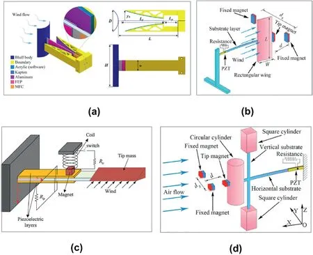
Fig.12.Structures of wind energy harvesters with various non-linear design vibration pick-up structures.(a)Galloping wind energy harvesting with two triboelectric nanogenerator boundaries acting as amplitude limiter[53];(b)Multi-stability to harvest the wind energy by a pair offixed magnets and magnets placed at cantilever tip [54];(c)Galloping energy harvester with piezo-electromagnetic synergy design [55];(d)VIVs-and galloping hybrid energy harvester with a magnet-based multi-stability design[56].
Guo[57]reported a hybrid design of pinwheel which coupled a triboelectric nanogenerator(TENG)and an electromagnetic generator(EMG).The demonstrator can harvest wind energy even at 1.7 m/s wind speed.TheIscandVocof the TENG output can reach 1.8μA and 24V,corresponding to the electric outputs of the EMG at 3.8 mA and 0.95V.The maximum output power density appears at 6 m/s wind speed,where TENG reach a power density of 0.12 mW/g and the EMG reaches a power density of 0.26 mW/g.
Chen[58]brings the integration of hybrid design one step further by designing a piezoelectric and triboelectric hybrid wind energy harvester consisting of a square flapping cantilever and two spindle-shaped outer paddles.The spindle-shaped outer paddles are optimized to enhance the vortex shedding near the flapping cantilever.Under the excitation of ambient wind,the piezoelectric and triboelectric part produce power outputs simultaneously.The cut-in speed of the device is reduced to 4 m/s.The voltage outputs increased in line with the wind speed.The peak voltage outputs(open circuit)of the piezoelectric and the upper triboelectric parts are 19.8 and 17.4Vrespectively at14 m/s wind speed.The maximum power outputs are 112μW and 76μWrespectively at 10 m/s wind speed with optimized load resistances of 0.6 MΩand 0.9 MΩ.
The hybrid design does not only benefit the MWEH with the windinduced-vibration-based design but also is suitable for the rotating wind energy harvester.Fan [59] proposed a rotating electromagnetic/triboelectric wind energy harvester.It consists of a rotating electromagnetic generator and a sliding triboelectric nanogenerator.Both the rotating and sliding units are sealed and isolated from the harsh environment.The cut-in speed of the present demonstrator is 4 m/s.The output of TENGs and EMGs increases with increasing wind speed.The maximum output voltages are observed at 15 m/s wind speed.The outputs are,for TENGs unit,41.6Vand for the EMGs unit,63.2V.The maximum output power is 0.36 mWand 18.6 mW,respectively at 9 m/s wind speed.Fan also demonstrated that the device is capable of charging a 1000 mF capacitor to 19.8Vin 30s.
Naturally,the hybrid energy harvester design concept is not restricted to triboelectric only,and a hybrid piezo-dielectric(PD)wind energy harvester is proposed[60].It is designed to efficiently harvest energy from low-speed wind using vortex-induced vibration.The harvester consists of piezoelectric ceramic(PZT)sheets on a cantilever and a vibro-impact(VI)dielectric elastomer generator(DEG)inside the bluff body,where PZT sheets transduce vibration into electricity and VI DEG transduces the impacts between the inner ball and the dielectric elastomer membranes.An analytical model of the harvester was established.The aerodynamic coefficients were identified by wind tunnel experiment.A numerical analysis is conducted based on the analytical model.The conjunction of the PZT and VI DEG for VIV energy harvesting enhancement effect is discussed in detail.The result suggests that when the harvester is working in the lock-in region,the VI DEG can generate much higher power than PZT.A parametrical study suggests a smaller mass,higher stiffness,and larger diameter bluff body is preferred to achieve a broad working wind range and an improved generation of power.
Guo[61]reported a multi-modal hybrid bridge energy harvester(HBEH)using both piezoelectric and electromagnetic effects.The configuration,fabrication,and characterization of the harvester are discussed in detail.It consists of a permanent magnet,a winding coil,a piezoelectric plate,an airfoil,and two cantilever beams attached to a base.The permanent magnet and airfoil arefixed on the upper cantilever as tip mass.A PZT plate is attached on thefixed end of this beam.A coil isfixed on the lower cantilever right under the upper cantilever.The coil is aligned in-line to the permanent magnet on the upper cantilever at a small distance.
The multi-modal hybrid bridge energy harvester operated at thefirst three resonances(11,38,and 43 Hz).It is capable of covering the frequency range from 11 to 45 Hz.Guo tested the dynamic response of the system under a sinusoidal base acceleration.Under 11.1 Hz-0.6gbase acceleration,the electromagnetic part could produce 2214.32μW maximum power with a 28Ωload at 1st resonance.The piezoelectric part produces 155.7μW 2214.32μWmaximum power with 130 kΩresistance when 0.4gacceleration is applied.A 6 m/s pulsating wind speed is used to evaluate the performance of the HBEH.Output voltages of 25 mV and 114 mV were observed from its electromagnetic and piezoelectric part respectively.

Fig.13.Various structures of hybrid wind energy harvester.(a)hybrid harvester design consisting of a pinwheel to a coupled triboelectric(TE)and electromagnet(EM)[57];(b)Rotating wind energy harvester consisting of a rotating body and a sliding body to a coupled triboelectric and electromagnet[59];(c)A novel hybrid piezo-dielectric(PD)wind energy harvester[60];(d)Multi-modal hybrid bridge energy harvester designed to combine piezoelectric and electromagnetic conversion methods[61];(e)Hybrid wind energy harvester consisting of two triboelectric nanogenerators(TENGs)and two electromagnetic generators(EMGs)[62].
Finally,the necessary structure introduced to realize hybrid design can be seamlessly integrated into fluid dynamic enhancement structures.Wang[62]propose a hybridized nanogenerator consisting of two triboelectric nanogenerators(TENGs)and two electromagnetic generators(EMGs).It is very compact(6.7 cm×4.5 cm x 2 cm)and lightweight(42.3g).As shown in Fig.13.f,the two triboelectric nanogenerators(TENGs)form an air-channel that can enhance the hydrodynamic performance of the electromagnetic generators.The TENG part of the hybridized nanogenerator can generate maximum output powers of 3.5 mW with a 3 MΩat a resistance load under 18 m/s wind speed.The power per unit mass and power per volume are calculated to be 8.8 mW/g and 14.6 kW/m3respectively.The EMG part produced an additional 1.8 mWover a 2 kΩresistance load.This has a power per unit mass of 0.3 mW/gandpower per unit mass/volume of 0.4 kW/m3.
5.Summary
The increasing number of online condition monitoring and IoT applications leads to a growing demand for miniature wind energy harvesters.This article gives an overall review of the recent research on MWEHs.Various types of wind energy coupling mechanism were discussed.The rotation-based(turbine and turbine-like)MWEHs show very reasonable output performance in high wind speed application scenarios.However,system size reduction results in a few significant challenges for the rotation-based coupling method including the proportionally decreasing performance on the turbine blade due to air drag and a proportionally increasing friction loss on the bearing.There have been some attempts to overcome those challenges to ensure an effective conversion of wind energy at a lower speed.However,most current studies in thefield of MWEHs are focused on wind-induced-vibration.Unlike the rotation-based MWEHs,wind-induced-vibration MWEHs mainly transform the wind into structural vibration via a hydrodynamic instability phenomenon.The increasing air drag due to the miniaturized process does not necessarily reduce its conversion efficiency.In fact,both galloping-based and flutter-based MWEHs are able to convert wind energy mainly thanks to the air drag.Also,wind-induced-vibration is completely free of bearing loss because this mechanism does not require the use of a bearing.All the above advantages make the wind-inducedvibrationfit perfectly the basic requirements of MWEHs,and especially so in the case of low wind speed application scenarios.
In the sub-catalogs of wind-induced-vibration MWEHs,vortexinduced vibration-based MWEHs have a unique advantage,and the vortex-induced vibration phenomenon is well-studied thanks to the pioneers working in thefield of hydrodynamics.Consequently,it is generally possible to build an analytical model for VIV-based MWEHs.As a result,the bluff body can be optimized based on numerical analysis,a main aspect of VIV-based MWEHs.The methods to enhance the fluid action force andfine-tune the vortex shedding frequency are covered in this review.An optimal efficiency can be achieved at lower wind speed with an appropriate design.The main drawback of VIV-based MWEHs is the relatively narrow operational wind-speed-range due to the characteristics of the VIV phenomenon.
As an alternative,aero-elastic flutter features a self-excitation and divergence characteristic.Unlike the VIV-based MWEHs,negative damping will appear when flutter-based MWEHs are subject to a wind that has a higher speed than the critical flutter speed.Since this phenomenon is divergent,the vibration amplitude of flutter-based MWEHs will be monotonically increasing along with the wind speed.One concern is that an unexpected higher speed wind(e.g.a sudden increase)in the partial application may cause irreversible damage to the MWEH.In addition,flutter-based MWEHs only start to work when the wind speed meets or is higher than the critical flutter speed of the coupling structure.As shown in this paper,methods to effectively reduce the critical flutter speed are widely discussed.Unfortunately,because of the complexity of the flutter phenomenon,an analytical model to reliably describe the flutter system behavior is as yet missing,but very much needed.
Galloping-based MWEHs share the positive characteristics of both VIV and aero-elastic flutter.Even though the analytical model for this phenomenon is not as well established as for VIV,it is possible to optimize the non-streamlined bluff body to obtain a higher fluid-action force.There is some literature that reports that through a specially designed bluff body,the device can change between VIV and galloping according to the wind speed.Furthermore,thanks to its non-linear damping,the galloping-based MWEHs do have a wide operational wind-speed range,and the divergence can be controlled at a defined level.This makes galloping-based MWEHs satisfactory over a great range of harvesting applications.
MWEHs can be improved by various performance enhancement methods.As well as the large number of strategies to enhance energy coupling efficiency by hydrodynamic methods,non-linear vibration pickup concepts are discussed and compared.The non-linearity can be introduced through an amplitude limiter or multi-stable design,both of which have proved to be very effective.
The use of new energy conversion mechanisms like triboelectric and piezoelectric methods make it possible to design a hybrid energy harvester which only depends on a single ambient energy.As a result,the overall conversion efficiency has a notable improvement.
Overall,with the current rapid development of the Internet of Things(IoT),a battery-based power supply strategy greatly limits the life cycle of anfinal application system.The energy harvester has become a critical and promising solution for an autonomous self-sustaining system.To develop an appropriate miniature wind energy harvester is required in countless applications already.A miniature wind energy harvester design which works at low wind speed with a wide operational wind speed range can significantly improve the operation cycle of many systems and can result in more robust IoT applications.
Declaration of competing interest
None.
Acknowledgements
The authors acknowledge thefinancial support from National Natural Science Foundation of China Grant No.61604023and National Natural Science Foundation of China(Grant No.61804016).

- Namo Materials Science的其它文章
- GUIDE FOR AUTHORS
- Editorial for a special issue“Nano energy materials and devices for miniaturized electronics and smart systems”
- Aim & Scope
- Low-power emerging memristive designs towards secure hardware systems for applications in internet of things
- Recent developments of stamped planar micro-supercapacitors:Materials,fabrication and perspectives
- Advanced architecture designs towards high-performance 3D microbatteries