Broadband achromatic metasurface filter for apodization imaging in the visible
Li Zhu ,Wang Changtao ,Kong Weijie ,Wang Yanqin ,Guo Yinghui ,Li Xiong ,Ma Xiaoliang,3,Pu Mingbo,Luo Xiangang*
1State Key Laboratory of Optical Technologies on Nano-Fabrication and Micro-Engineering,Institute of Optics and Electronics,Chinese Academy of Sciences,Chengdu,Sichuan 610209,China;
2School of Optoelectronics,University of Chinese Academy of Sciences,Beijing 100049,China;
3National Institute of Defense Technology Innovation,Academy of Military Sciences PLA China,Beijing 100071,China
Abstract:Apodization has found many important applications in imaging and optical communication.Traditional apodization methods are based on the phase or amplitude modulation,suffering from either narrow working bandwidth,or reduced spatial resolution.Here,a broadband achromatic metasurface filter is proposed to realize apodization imaging without sacrificing the spatial resolution.With this filter,a nearly dispersionless phase modulation in the entire visible waveband can be achieved.The simulated results indicate that the focusing efficiency of the metasurface filter is twice larger than that of the phase filter and the imaging contrast can be improved by three times with the metasurface filter compared to the Gaussian filter.The sidelobes in the point spread function can also be efficiently suppressed to the scale of 10-5 in the whole visible spectrum ranging from 400 nm to 700 nm with our design.Additionally,the resolution of diffraction limit or even sub-diffraction can be achieved with this method.
Keywords:apodization;broadband;dispersionless;metasurface
1 Introduction
Generally,noticeable sidelobes exist in the point spread function (PSF) of a diffraction-limited imaging system[1].In most situations,these ‘noises’ are often small and can be ignored in many imaging systems.However,they have significant influence in the situation when resolving two point-objects with large intensity contrast.This situation is very common in astronomy,for example,when investigating the presence or absence of weak companion star next to a bright star[2].In addition,the strong sidelobes have the potential to cause degraded image and decreased spatial resolution,which is especially unacceptable not only in previously introduced astronomical applications but also in the applications of synthetic aperture radar imaging[3]and phase-contrast imaging microscopy[4].
To relieve the influence of sidelobes,apodization methods have been developed and successfully used in many optical applications,such as coronagraphs in astronomy[5]and spectral tailoring in silicon integrated Bragg grating devices[6].Theoretically,apodization focuses on the optimization of entrance or exit pupil of an optical system to get a desired light field distribution (i.e.the systematic PSF) with decreased sidelobes[7].In general,apodization is equal to an attenuating mask to suppress the intensity of sidelobes in the diffraction pattern so that certain weak details can be distinguished.Classical amplitude apodization usually modifies the pupil transmittance by introducing specifically designed attenuation masks into the optical system to modulate amplitude at the pupil plane[8],leading to the decreased spatial resolution and throughput of the imaging system.Another method to realize apodization is manipulating the phase at the pupil plane[9]by diffractive optical elements.Compared to amplitude apodization,a better resolution,higher throughout and higher contrast of the imaging system can be achieved with phase modulation.However,the diffractive optical elements are normally made of glass with specific etch depth to realize the desired phase modulation,which exhibits strong dispersion and restricts the working bandwidth considerably.Although we can combine various types of optical materials with different refraction index to reduce the dispersion,this results in bulky structures and complex fabrication inevitably.Alternatively,apodization can be carried out by geometrically remapping the pupil plane of the optical system to obtain the desired apodization pupil function.This approach is called phase-induced amplitude apodization[10],and it can theoretically achieve lossless modulation in a broadband spectrum by virtue of introducing two aspheric mirrors into the imaging system.This access offers high imaging contrast without the sacrifice of resolution and throughout.However,this approach normally uses two additional aspheric mirrors in a reflective optical setup,which is comparatively complicated and leads to more strict requirements on optical and mechanical fabrication and assembly.
Recently,the metasurfaces based on artificially structured materials have excited much attention because of their extraordinary ability for the flexible modulation of electromagnetic wave.In contrast to 3D metamaterials,the metasurfaces have a planar and ultrathin structure,which is easier to be fabricated and assembled[11].They have been demonstrated to be a promising substitute for traditional optical component and show excellent performance in many applications[12-16],such as apodized focusing[17-18],dispersion and polarization manipulation[19-20],and orbit angular momentum generation[21].Among them,one type of metasurface based on the geometric phase is increasingly promising and compelling in broadband dispersionless phase modulation[22].In principle,the modulated phase is only dependent on the orientation of the unit cell in metasurface[23].Based on this theory,many abnormal phenomena and novel optical devices have been proposed,including broadband spin Hall effect[24],planar meta-lenses[25],and optical holography[26].Therefore,the metasurface with geometric phase modulation also provides a new and promising avenue for broadband achromatic apodization imaging.
In this paper,the metasurface apodization filter (MAF)is proposed to achieve broadband achromatic apodization imaging in the visible.Benefiting from the geometric phase modulation,MAF can achieve dispersionless phase modulation compared to traditional diffractive optical elements.The simulation results indicate that the performance of our approach outperforms than other apodization methods.It is also verified in our imaging simulation that the proposed MAF can provide a resolving ability that can even surpass the diffraction limit in the entire visible waveband from 400 nm to 700 nm with improved imaging contrast.
2 Principle and design
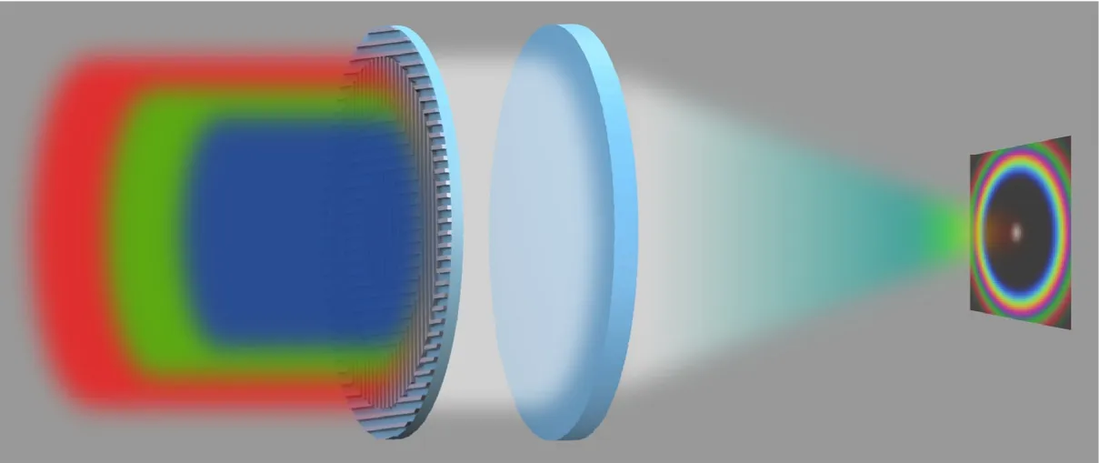
As indicated in Fig.1,under the condition of paraxial approximation,the PSF of an apodization imaging system modulated by MAF can be depicted as[1]:

where f is the focal length of the achromatic lens used in the apodization imaging system,R represents the semi-diameter of the entrance pupil aperture and φMAFdenotes the phase modulation function of MAF,respectively.In our simulations,the diameter of the optical system is set to be 8 mm with a focal length of 1000 mm.
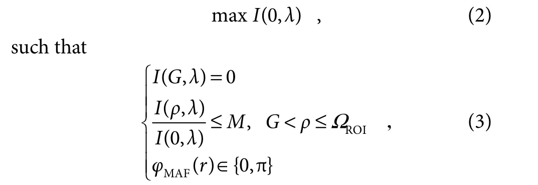
The design of MAF could be described as an optimization problem of

here,ΩROIis the region of interest (ROI) where sidelobes of the PSF are constrained by MAF.In general,this region contains a mainlobe and several sidelobes.The mainlobe determines the resolving power and the sidelobes mainly affect the image quality.The performance of the MAF is described in this paper with the spot size G normalized by Rayleigh diffraction limit of central wavelength (RAIRY,defined as 0.61λc/NA,where λcand NA represent the central wavelength and numerical aperture),the Strehl ratio S,and the ratio between maximum intensity of sidelobes and central intensity M within ROI.Through an optimization algorithm like linear programing[27]or particle swarm optimization[28],the specific phase distribution of MAF can be obtained.Assuming that the proposed broadband apodization imaging system with an entrance pupil diameter of 8 mm and a focal length of 1000 mm works in the visible waveband from 400 nm to 700 nm,two different MAFs with specific normalized phase-jump positions r are designed by the aforementioned optimization procedure and their performances at the central wavelength of 550 nm are presented in Table 1.

Fig.1 Schematic of the apodization imaging system

Table 1 Performances of MAFs
Based on the principle of geometric phase,the orientation of every nanostructure in our metasurface is determined to realize the required broadband dispersionless phase modulation.To illustrate the working principle of MAF,for convenience,every nanostructure of the metasurface is regarded as an ideal dipole without considering the influence of material and geometric size (period,length,width,and height) and its orientation direction is assumed to form an angle θ regarding x axis.In this way,as circularly polarized (CP) light normally impinges on the dipole,the transmitted light field could be written as[18]:

where the subscripts L and R denote the left CP and right CP,respectively,andexandeyrepresent the unit vectors along x and y directions,αeis the electric polarizability,andex±ieyindicates the vector for left-handed (+) and right-handed (-) CP,respectively.Accordingly,linear polarization (LP) can be decomposed as LCP and RCP.For a normal x-LP incident light (the case for y-LP is similar),the transmitted light field can be expressed as,

By substituting Eq.(4) into Eq.(5),we can get:

Apparently,the amplitude of transmitted crossed polarized light continuously varies with the angle θ,while its phase has only two values,0 or π.In order to maximize the efficiency of the metasurface,the angle θ is set to±45°.Hence,our proposed MAF is comprised of two kinds of rectangular metallic nanostructures with different orientations (θ=±45°) etched on a glass substrate.For the convenience of fabrication,Cr was chosen as the material of the nanostructure in our MAF,and we used the optical parameters from Palik’s book to simulate the response of the nanostructure.The size parameters of the nanostructures are optimized by the commercial software CST Microwave Studio to obtain the maximum efficiency.The incident light was from the substrate direction and set to x-LP with the wavelength from 400 nm to 700 nm,and the nanostructures with different sizes were simulated.As shown in Fig.2(a),we choose the nanostructure parameters with 270 nm×270 nm period,270 nm length,120 nm width,and 70 nm depth,which can be easily fabricated by electron beam lithography.The light-field manipulation ability of the nanostructure is also simulated as presented in Fig.2(b).The simulated transmittance (red line) of the nanostructures with varying angle θ agree well with the theory (green line).Besides,as illustrated in Fig.2(c),for a given angle θ,the efficiency has neglectable difference and the modulated phase shift of the transmitted light for two nanostructures is approximately fixed to 180° in a broad spectrum from 400 nm to 700 nm,which demonstrates the broadband dispersionless phase modulation ability of metasurface based on the geometric phase principle.According to the constraints on MAF,the metasurface is optimized to contain several regions with specific normalized radius.The nanostructures are all the same in each annulus so that they are connected to form a kind of subwavelength metallic nano-grating.These two different nanostructures are distributed alternatingly in neighboring annuli as indicated in Fig.2(d).Since the orientations of the nano-gratings in neighboring rings are orthogonal to each other,following the geometric phase,the metasurface can theoretically realize nearly perfect 0 or π dispersionless phase manipulation for the broadband incident light.

Fig.2 (a) Schematic of the nanostructure in metasurface;(b) Transmittance and phase shift of nanostructures with different θ at the central wavelength of 550 nm;(c) Transmittance and phase shift of nanostructures with θ=±45° from 400 nm to 700 nm;(d) Schematic of the metasurface apodization filter
3 Results and discussion
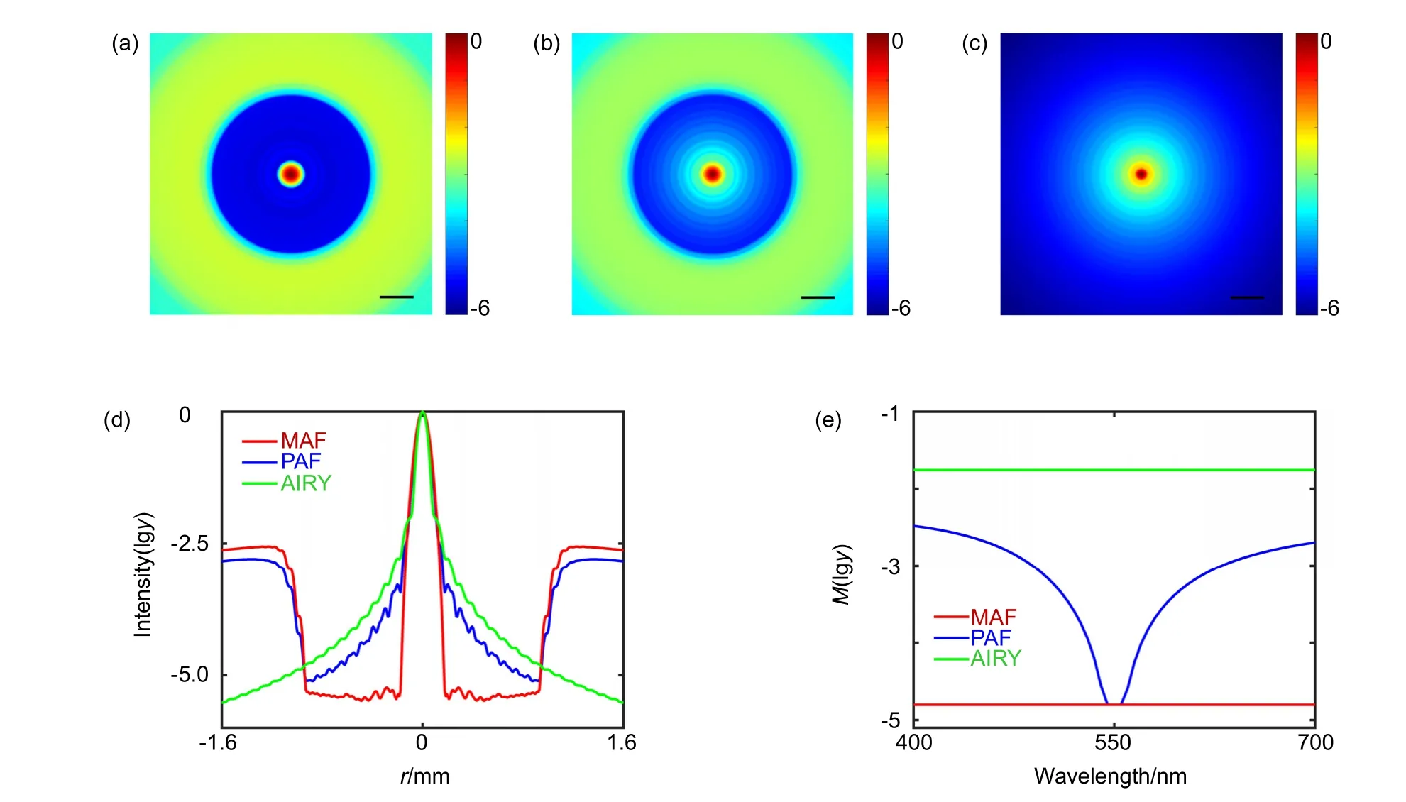
In order to show the advantage of our method,the PSF simulations among metasurface apodization filter,phase apodization filter (PAF),and diffraction-limited imaging(AIRY) are presented in Fig.3.Since MAF is essentially one kind of special PAF,which can work in a broadband spectrum without dispersion,PAF is designed to have the same phase-jump positions as MAF1.The broadband PSF is calculated by the linear superposition of every PSF of single working wavelength with an interval of 5 nm.If the intensity of the incident light for different wavelengths are the same,the broadband PSF can be calculated as follows:

where ϕ(r) is the modulated phase of MAF or PAF,while it is set to zero for diffraction-limited imaging.As plotted in Figs.3(a)∼3(d),the sidelobes within ROI are both suppressed with MAF and PAF compared to the diffraction-limit imaging,while the performance of PAF is obviously worse than MAF due to the inherent material dispersion.Here,the K9 glass is used as the material of PAF and the phase difference Δϕ of two neighboring rings in PAF can be depicted as:

In equation (8),d and n represent the etched depth of rings in PAF and the refractive index of material,respectively.The corresponding etched depth for central working wavelength of 550 nm is about 530 nm.However,due to the inherent dispersion property of material,the modulated phase for other wavelengths will inevitably deviate the desired phase,leading to the distortion of PSF.The normalized maximum sidelobe intensity of PSFs under different working wavelengths are compared among MAF,PAF and diffraction-limited imaging in Fig.3(e).It is found that the desired M can only be achieved in a very narrow band (about 10 nm in our simulation) with PAF.Consequently,as discussed above,it is extremely difficult to realize apodization modulation in the broadband spectrum with the traditional phase apodization approach.Fortunately,the metasurface based on the geometric phase principle can address this problem and we can realize a constant M in the entire visible spectrum from 400 nm to 700 nm.The efficiency of these two methods are defined as follows:

Fig.3 Broadband PSFs of (a) metasurface apodization filter,(b) phase apodization filter,and (c) diffraction-limited imaging.Scalar bar:400 μm;(d) Radial normalized logarithmic intensity distributions of (a),(b) and (c);(e) The comparison of M for three imaging methods with different working wavelength in logarithmic form

where λ1and λ2represent the lower and upper limits of the working waveband.The efficiency of MAF and PAF are 21.43% and 1.05% respectively,which exhibits the outstanding superiority of MAF.Even though the transmittance of our metasurface is not very high (only about 10% in the working waveband),benefiting from the broad working waveband,the total efficiency of MAF is still twice larger than PAF.Additionally,the efficiency of metasurface can be improved substantially to about 80%if a reflective design is adopted[29].
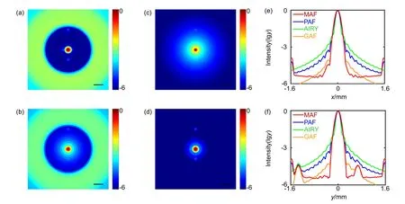
To characterize the apodization performance of MAF1in the visible waveband ranging from 400 nm to 700 nm,a point object with four companion point objects of the same intensity is used as target to simulate the common astronomical observation.The intensity contrast is set to 30000.The transmittance of Gaussian apodization filter(GAF) is essentially a Gaussian window function with a standard deviation of 0.4385,leading to the same M within ROI as MAF1.Four companion point objects are set to be 2.4RAIRY(-x),1.8RAIRY(+x),10RAIRY(-y),and 5RAIRY(+y) far from the central point object,respectively.Obviously,as shown in Figs.4(a)∼4(d),only the weak point object in -y direction can be resolved in the diffraction-limited imaging and the others are all immersed in the sidelobes of the central point object’s image.One more point object can hardly be noticed in +y direction with PAF.By using GAF,all the point objects can be distinguished except the point object in +x direction.Though it is a little hard to resolve the point object in +x directions with MAF1,by comparing Fig.4(e) with 4(f),it is found the mainlobe in +x direction is extended noticeably compared to the mainlobe in ±y directions which suggests the existence of a weak point object in +x directions.
To further verify the performance of our method,an extended target (‘E’ letter,the distance between two neighboring lines is 1.0RAIRY,and the line width is 20 μm)is imaged with MAF2and GAF in the visible spectrum from 400 nm to 700 nm.The standard deviation of GAF’s transmittance is 0.7143.As can be clearly seen in Figs.5(a)∼5(c),these two filters have the same M value,while the mainlobe of MAF2is largely suppressed.We can easily distinguish the“E”letter with MAF2in Fig.5(d)compared to that in Fig.5(e).The normalized intensity distributions along the labeled dashed line are compared in Fig.5(f).It is found that the contrast is substantially improved from 0.17 to 0.54.Though at the cost of a limited ROI and decreased efficiency,the metasurface apodization method provides an effective access for improving imaging contrast.

Fig.4 Broadband images with (a) metasurface apodization filer,(b) phase apodization filter,(c) diffraction-limited imaging,and(d) Gaussian apodization filter,Scale bar:400 μm;(e) Normalized logarithmic intensities of (a),(b),(c),and (d) in x-direction;(f) Normalized intensities of (a),(b),(c),and (d) in y-direction

Fig.5 Broadband PSFs of (a) MAF and (b) GAF.Scale bar:100 μm;(c) Radial logarithmic intensity distributions of (a)and (b);Broadband images of (d) MAF and (e) GAF.Scale bar:30 μm;(f) Normalized intensity distribution along the labeled dashed line in (d),(e) polarization rotation angle (a) and ellipticity (b) of the weak chiral metasurface
Compared to other apodization imaging methods,our method is easy to employ through a simple and compact MAF.Even though the metasurface in our apodization method suffers from a relatively low efficiency,its total efficiency is still much higher than that of the phase apodization method because of the broad working bandwidth.Furthermore,the MAF could achieve higher efficiency with better fabrication facilities,since its transmittance increases with the decrease of the width of rectangular nanostructure.Additionally,there are some other effective solutions to solve this problem,like adopting a reflective structure,a high-sensitivity detector,longer exposure time or specific image enhancement algorithm.
4 Conclusions
In summary,the MAF is proposed to realize broadband achromatic apodization imaging in the entire visible waveband.Benefiting from the geometric phase principle,the proposed MAF solves the problem of narrow working bandwidth in the phase apodization method.The intensities of sidelobes can be effectively reduced to the scale of 10-5with our method.In addition,the resolution of diffraction limit or even sub-diffraction is verified.The simulation results match well with our design and verify the good performance of MAF.Our method is believed to be a promising alternative in broadband apodization imaging,and may promote the development in the applications of astronomical observation and optical communication.
Acknowledgements
This work was supported by National Natural Science Foundation of China (61905073,61875253,61675207)and Youth Innovation Promotion Association of the Chinese Academy of Sciences (2019371).Zhu Li and Changtao Wang contributed equally to this work.

