Ring artifacts correction based on the projection-field in neutron CT*
Sheng-Xiang Wang(王声翔), Jie Chen(陈洁),†, Zhi-Jian Tan(谭志坚), Si-Hao Deng(邓司浩),Yao-Da Wu(吴耀达), Huai-Le Lu(卢怀乐), Shou-Ding Li(李守定),Wei-Chang Chen(陈卫昌), and Lun-Hua He(何伦华)
1Spallation Neutron Source Science Center,Dongguan 523803,China
2Institute of High Energy Physics,Chinese Academy of Sciences(CAS),Beijing 100049,China
3Institute of Physics,Chinese Academy of Sciences,Beijing 100190,China
4Key Laboratory of Shale Gas and Geoengineering,Institute of Geology and Geophysics,Chinese Academy of Sciences,Beijing 100029,China
5Innovation Academy for Earth Science,Chinese Academy of Sciences,Beijing 100029,China
6College of Earth and Planetary Sciences,University of Chinese Academy of Sciences,Beijing 100049,China
Keywords: ring artifacts correction,neutron CT,projection field
1. Introduction
Neutron has unique superiority in comparison with xray in many respects, as it is sensitive to nuclide density instead of electron density. Neutron computed tomography(CT) becomes one of the state-of-the-art nondestructive testing technologies,which has developed rapidly in recent years and acquires a lot of important achievements in different research fields,such as neutron tomography of Li distribution for cells,[1–3]water flow in rooted soil,[4]four-dimensional (4D)imaging combined with x-ray tomography,[5–7]etc.
However, because the limitation in manufacturing technology of high-resolution scintillation screen leads to inconsistent response among the neutron detector channels,ring artifacts will appear on the reconstructed images,blur the shape of structures, degrade the image quality and testing effect.For example,in the recently published article,[7]the ring artifacts inevitably appeared on the reconstructed lithium battery.Therefore,it is necessary to implement the correction through an effective method.
Ring artifacts also happened in the early research of x-ray CT but are getting rare with the development of x-ray detector manufacturing technique. There have been proposed some projection-field and image-field-based methods for the ring artifact’s correction on x-ray CT, which can also be applied to neutron CT. The existing projection-field-based methods either adopt the moving average method[8]or give priority to the median filtering[9]which unavoidably reduces the image resolution, or try to find the error channels by using statistics theory and interpolation subsequently, but most of them are applicable to the cases of large errors.[10]One of the correction methods based on image-field verified that the corrupted image can be restored essentially without compromising image resolution,[11]thus making it accepted widely.
In this work, we propose a ring artifacts correction method based on the projection-field,it can remove the ring artifacts without reducing the image resolution,and avoid overcorrection in comparison with one of the correction methods based on the image field (RCI).[11]Also, the corrected projections can be used for other algorithm researches, which is another advantage of correction method based on projectionfield.
2. Materials and method
2.1. Data preparation and experimental setup
We first use the digital Shepp–Logan phantom as a sample for method evaluation. The setting of parameters in projection acquisition and image reconstruction mimics that of the neutron CT system used in our physical experiments,360 equiangular projections over 360°are simulated for a CT scan with a parallel geometry, and each projection has a size of 512 pixel×512 pixel.
Two physical samples are performed on the neutron CT platform, one is a cylindrical metal block made of boron carbide and lead, the other is a cylindrical rock. The cylindrical model is tested on the CT platform at the China Advanced Research Reactor (CARR),[12]using a polychromatic cold neutron beam collimated by a pinhole with an L/D of 300 and a neutron flux of 5×10⁶neutrons·cm−2·s at the imaging position. The full-scan tomography is composed of 500 projections in steps of 0.72°. For each angular step, a projection is taken with an exposure time of 60 s, which is recorded by a neutron detector with a 100-µm ZnS/6LiF scintillator screen and a CCD camera(Andor,UK)in combination with an optical system using Nikon photo lens(Nikon,Japan).The camera array has 2048 pixel×2048 pixel with a pixel size of 13µm.
The cylindrical rock is tested on the general purpose powder diffractometer (GPPD)[13]at China Spallation Neutron Source (CSNS). The accelerator produces a beam power of 100 kW and the neutron flux is about 106neutron·cm−2·s at the sample stage. A half-scan tomography is composed of 180 projections in steps of 1°. The exposure time is 120 s for each projection, and the projections are recorded by a neutron detector consisting of a 50-µm ZnS/6LiF scintillator screen, a CCD camera(Prinston Instrument,USA),and an optical system using Nikon photo lens(Nikon,Japan). The camera array has a size of 2048 pixel×2048 pixel with a pixel size of 15µm.
2.2. Method
The errors come from inconsistent responses among the detector channels,mainly due to the difference in uneven scintillator thickness. Line or strip errors are produced in the sinogram with the data acquisition. Sometimes, the strip errors are indistinguishable in the sinogram and they are difficult to remove out of the projection-field.
When ring artifacts appear in the reconstructed slices,the errors must be visible in the filtered sinogram before backprojection, so the first step to highlight the strip errors in the sinogram is to implement Ram–Lak filtering, which can be written as

where|ω|is an original ramp function,and

is a window function,zero energy is contained outside the frequency interval(−Γ,Γ)with

where δ is the projection sampling interval. The impulse response of the filter can be described by


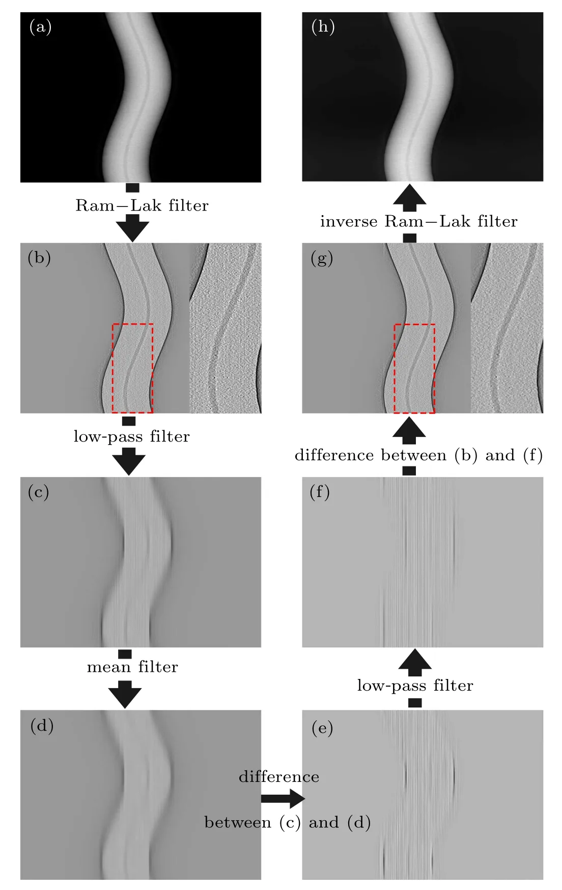
Fig. 1. Workflow of proposed ring artifact correction based on projection field.
After Ram–Lak filtering, the strip errors become apparent, and low pass filtering is used on each detector channel to remove the high frequency information of the sample. The next step is to remove low frequency information of the sample but keep the errors. Mean filtering and difference are performed at each angle among the channels.
However, as the operation of mean filtering moves few sample signals to contiguous channels, inevitably, we need one more step of low pass filtering in each channel to correct the adverse effect. Now,the errors can be extracted from the filtered sinogram. After achieving the corrected filtered sinogram,the corrected sinogram can be obtained through inverse Ram–Lak filtering. By the way,if the filtered back projection (FBP) can be accepted to implement reconstruction,direct back-projection on the corrected filtered sinogram will result in an image without ring artifacts. The workflow of the method is shown in Fig.1,in which the red dotted frame represents the region of interest(ROI)(Figs.1(b)and 1(g)).It can be seen obviously that the proposed method corrects the strip errors from the ROI.
3. Results
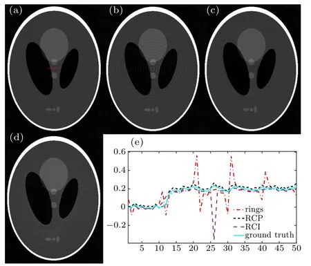
The results of the digital phantom used to evaluate the efficiency of the ring correction are shown in Fig. 2. The phantom without and with rings are shown in Figs. 2(a) and 2(b), respectively. Figures 2(c) and 2(d) are the results after using RCI and RCP, respectively. To compare these images easily,the profiles of all the compensated images are shown in Fig.2(e). All profiles are extracted from the same position of each figure,which is across the center of rotation and marked with the red line in Fig.2(a).The RCI can correct the rings,but a dark dot can be found in the center of the rings in Fig.2(c).That low index means the overcorrection when using RCI.

Fig.2. Comparative results of ring artifact correction based on digital phantom: (a) without ring artifacts, (b) with ring artifacts, (c) after using RCI method,(d)after using RCP method,and(e)profiles of each method,respectively.
Oppositely, the proposed RCP corrects the rings effectively. The profiles across the center of the rings can help to display the results more clearly. The profile of RCI turns smooth between the 10th and 13th pixels, but the profile of RCP can match the ground truth well, which means that the using of RCP will not reduce the image resolution. At the same time, the RCP can avoid overcorrection in comparison with the RCI in the center of the rings, the 26th pixel in the profile. In a word, the RCP is an effective method to implement the ring correction.

Fig.3. Reconstructed slices and corresponding ring artifacts of metal block by different correction methods. Columns (a) and (b) are slices of different structures at different heights. Display window: reconstructed slices,[0 0.008]µm−1;errors,[−5×10⁻⁴ 5×10⁻⁴]µm−1.
The results of the cylindrical metal block are shown in Fig. 3, and the FBP is used to implement the reconstruction with an image size of 709×709. It can be seen both the RCI and RCP can correct the ring artifacts. However, to see the correction efficiency clearly, the differences between reconstructed slices with and without (W/o) correction, named errors, are shown in Fig. 3. It can be found that some apparent structure information of the metal block displayed in Figs.3(a3)and 3(b3). Conversely,figures 3(a5)and 3(b5)exhibit the ring artifacts without sample structure.
Both RCI and RCP can correct the ring artifacts well and provide beneficial images. However, the results are inconsistent by the two different methods. The magnified ROIs in the red dotted box of slice (a) and the same pixel region of slice (b) in Fig. 3 are displayed in Fig. 4, and the image noise for isotropic spatial resolution is inversely proportional to the square of the sampling distance,[14]showing a chrysanthemum-like structure. It will lead the sample structures to be misunderstood to a certain extent. This kind of result comes from the heterogeneous division of strip artifacts in the polar coordinates when using RCI. At the same time,the standard deviations of selected red dotted areas become 2.10×10⁻⁴and 2.17×10⁻⁴from 3.21×10⁻⁴for slice (a),become 1.96×10⁻⁴and 2.17×10⁻⁴from 2.90×10⁻⁴for slice(b)by using RCI and RCP,respectively.

Fig.4. Magnified ROIs in red dotted box of reconstructed slices(a)and(b)as shown in Fig.3.
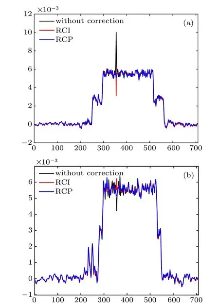
Furthermore, for image-quality quantification, the intensity profiles of a line in the reconstructions without and with ring artifacts correction are displayed in Fig.5. For slice(a),the attenuation coefficient at pixel 355(the center of the rings)is 10×10−3µm−1without correction,after correction by using RCI, it becomes 3.1×10⁻³µm−1, well below the average value of 5.5×10⁻³µm−1. At the same time, the value is 5.5×10⁻³µm−1after correction by using the proposed RCI. For slice (b), the value becomes 6.3×10⁻³µm−1and 5.8×10⁻³µm−1from 4.2×10⁻³µm−1by using RCI and RCP, respectively. Undoubtedly, the RCP has obvious overcorrection in comparison with RCI.

Fig. 5. Intensity profiles of a line in reconstructions without and with ring artifacts correction by using RCI and RCP,with the position of line indicated in Fig.3(a1).

Table 1. Standard deviation and center value for ROIs,with all ROIs of different images located in the same region as that marked by solid red box in Fig.4.
The cylindrical rock slice displays a lower signal-to-noise ratio and more serious ring artifacts than those slices of the metal block. The strip errors caused by the inconsistent response can be seen obviously in the sinogram of the rock(Fig.6). After correction by using the proposed PCP,the strip errors in the sinogram and the ring artifacts in the slice completely disappear,and the reconstructed result can provide effective structural information for further analysis,which is the core of the technique of neutron CT.

Fig. 6. Sinogram and reconstructed slices of cylindrical rock without and with correction. Display window: reconstructed slices,[0 0.004]µm−1.
4. Conclusions
In this work,a ring artifact’s correction method based on the projection field is proposed and proves to be effective. The simulated example proves that it can remove the ring artifacts well without reducing image resolution. In the experiment on the metal block, the errors between images without and with correction do not show any structure information of the sample, which means that the overcorrection will not happen by this method. It can also solve the ring artifacts at different levels. This method is useful in neutron CT in the case of low flux at the sample position,long exposure time and imperfect neutron scintillation screen manufactured technologically. In addition, this method can be used in other CT systems with different sources besides neutron source.
- Chinese Physics B的其它文章
- Process modeling gas atomization of close-coupled ring-hole nozzle for 316L stainless steel powder production*
- A 532 nm molecular iodine optical frequency standard based on modulation transfer spectroscopy*
- High-throughput identification of one-dimensional atomic wires and first principles calculations of their electronic states*
- Effect of tellurium(Te4+)irradiation on microstructure and associated irradiation-induced hardening*
- Effect of helium concentration on irradiation damage of Fe-ion irradiated SIMP steel at 300 °C and 450 °C*
- Optical spectroscopy study of damage evolution in 6H-SiC by H+2 implantation*

