
Evolution of ion-irradiated point defect concentration by cluster dynamics simulation*
2021-05-24 02:23:52ShuaishuaiFeng冯帅帅ShashaLv吕沙沙LiangChen陈良andZhengcaoLi李正操
Chinese Physics B 2021年5期
Shuaishuai Feng(冯帅帅), Shasha Lv(吕沙沙), Liang Chen(陈良), and Zhengcao Li(李正操)
1Key Laboratory of Advanced Materials(MOE),School of Materials Science and Engineering,Tsinghua University,Beijing 100084,China
2Key Laboratory of Beam Technology and Material Modification(MOE),College of Nuclear Science and Technology,Beijing Normal University,Beijing 100875,China
3School of Materials Science and Engineering,Shanghai Jiao Tong University,Shanghai 200240,China
4The Department of Engineering Physics,Tsinghua University,Beijing 100084,China
Keywords: ion irradiation,point defect concentration,cluster dynamics simulation
1. Introduction
Key materials for nuclear plant become increasingly embrittled by exposure to neutrons from the reactor core over the course of their service period. The microstructures induced by irradiation include solute clusters, matrix damage,and grain boundary segregation of brittle elements, which could continuously evaluate with time.[1–3]For example, the swelling caused by the cavities and bubbles will make the ductile to brittle transition temperature (DBTT) increase by~100°C.[4]The microstructure evolution is related to factors of three aspects: irradiation conditions (fluence, fluence rate, temperature, etc.), material compositions (elements and content, etc.), and the original microstructure (phase, grain boundary size).[5–8]However,due to the microstructure complexity of the irradiated materials and the objective limitation of service environment,it is very hard to study and predict the long-term evolution of microstructures through experimental methods.[9,10]Therefore, the research on simulation methods have been paid more focuses.
For different time and space scales, the microstructure evolution adopts different simulation methods. The irradiated point defects behavior of generation, diffusion, recombination,and clustering,which happens at the atomic scale of 10−15seconds. The density functional theory (DFT), molecular dynamics (MD), kinetic Monte Carlo (KMC), and other methods can well calculate the formation energy and diffusion energy of point defects in the evolution process,so as to simulate the evolution behavior of point defects.[11]Furthermore,the macroscopic properties of nuclear materials that are more concerned on the engineering scale,it is necessary to simulate and predict the microstructure evolution behaviors over several years or even decades.
Cluster dynamics(CD)are more suitable for long-period microstructure evolution behavior, due to its less computing resource occupation and higher computational efficiency.[12]CD method is a mesoscopic method based on the mean field rate theory (MFRT), and could be considered as an extension of MFRT model.[11]In the rate theory, it is assumed that the concentration of defects is uniform on the basis of mean field,so the ordinary differential equation is used to describe the rate change of defects concentration under mean field.[13]On the basis of that, CD method describes point defect clusters in addition to describing self-interstitial atom(SIA) and vacancy.[11]The evolution of clusters is regarded as a series of chemical reactions (absorption and release of point defects by clusters), to describe the evolution of cluster concentrations.[12]Through numerical solution of the equations,the evolution of clusters concentration can be obtained,and the characteristic physical quantity such as size, number density and volume fraction of clusters can be calculated.[12]
Heavy ion irradiations at high dose rates are often used to simulate the neutron irradiation on the microstructural evolution of reactor structural alloys.[14]However,many differences in the resultant modes of damage arise from the ion implantation effect.[14]The implanted ions can not only cause matrix damage, but also act as effective interstitial atoms,[15,16]which affects the evolution of defect clusters and suppress the void swelling by recombination with vacancies.[15,17–19]However, there is no corresponding vacancy generated to recombine with the implanted ions. This paper simulates and studies the effect of ion implantation on the concentration of point defects under 2.8-MeV Fe self-ion irradiation in pure Fe at 290°C (the reactor pressure vessel in service operates at 290±30°C[20,21]), to avoid composition changes. We first present the employed cluster dynamics modeling methods, then study and analyze the effect of ion implantation on defect concentration in high-dose heavy ion irradiation.
2. Modeling
SRIM simulation is based on the binary collision approximation(BCA)method,which can be used to simulate the ions and neutron irradiation experiments, calculate the displacement per atom (dpa) of ion irradiation. There are two basic options in SRIM to compute ion-induced displacement damage parameters: (i) “ion distribution and quick calculation of damage,” based on Kinchin–Pease model, referred to as K–P method, and (ii) “detailed calculation with full damage cascades,”referred to as F–C method. According to the research of Stoller et al.,[22]the damage energy obtained from the K–P calculation mode of SRIM was used to calculate the displacement damage,in order to be consistent with the standard NRT model.[23]The NRT model was developed by Norgett,Robinson,and Torrens to compute the number of displacements per atom (dpa) for a PKA with a given energy. This model is broadly adopted by the international radiation effects community and continues to be the internationally recognized standard method for computing atomic displacement rates. The simulation study employed the cluster dynamics equations established by Duparc and Moingeon et al.[24]to describe the rate of defect cluster concentration change over time, assuming that only SIA and vacancies are mobile:[24]


In the case of electron irradiations,more than 99%of the point defects are created in an isolated way.[24]The production rate G is equal to NRT rate,which can be calculated using the SRIM-2013 code.[25]In the case of neutron or heavy ion irradiations,when primary damage is created in displacements,a significant fraction of defects were not monomer SIA and vacancy defects, but rather clusters of defects.[11]MD calculations show that the NRT approach leads to an overestimation of the defect production rate. For iron, the defect production rate calculated by molecular dynamics is about 30%of the NRT rate.[26]Therefore, production rate G is equal to 0.3 times of NRT rate. The data from VACANCY.TXT and RANGE.TXT files of SRIM was converted to give defect production and interstitial injection rates,with simulation parameters[16]as shown in Table 1.

Table 1. Radiation related parameters.
Initially, thermal equilibrium concentrations are set for point defects, i.e., single interstitial and single vacancy, and the concentrations of all other defect clusters are set to zero.The other data introduced in the model concern point defect and clustering, summarized in Table 2. These data are the same as those in Ref.[24].

Table 2. Related parameters of cluster dynamics model.
3. Results
3.1. SRIM simulation
The displacement damage is determined using the damage energy obtained from the K–P method,and the total number of calculated ions is set to 105. Figure 1(a) shows the depth distribution of displacement damage and injected ion concentration of pure iron irradiated by Fe ions at 2.8 MeV.The peak of displacement damage is 5 dpa at about 825 nm.At depth of 0 nm–825 nm,the displacement damage increases with depth. While for 825 nm–1300 nm, the displacement damage decreases with depth,and the displacement damage at 1260 nm is 0.1 dpa.
The peak of the implanted ion concentration is 1.3×10⁻³, at about 990 nm. The implanted ion concentration at 195 nm is about 1.4% of the peak concentration, indicating that only a small part of the implanted ions stopped near the surface area at an energy of 2.8 MeV.The implanted ion concentration increases from 200 nm to 990 nm. At depth of 990 nm–1300 nm, the implanted ion concentration decreases with depth, and it is about 3.2% of the peak concentration at 1305 nm.
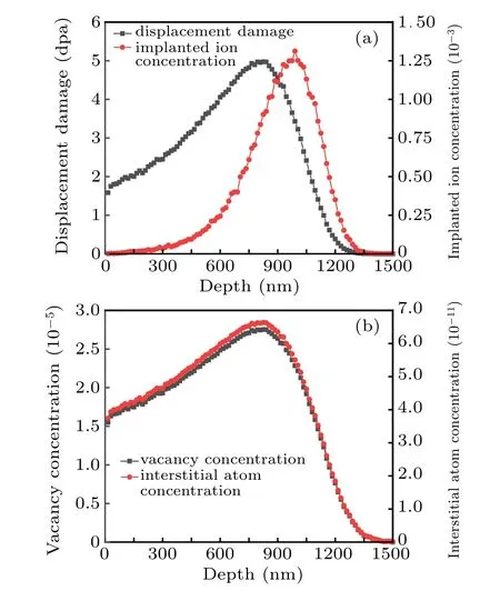
Fig.1. (a)The distribution of displacement damage and implanted ion concentration,and(b)distribution of equilibrium concentration of point defects with depth.
At 750 nm–1000 nm, the values of displacement damage and implanted ion concentration are both at a high level.Then, we estimated the concentration of point defects in the final state, and compared concentration of point defects and implanted ions to estimate the influence of the implanted ion effect on point defects concentration. According to Christian and Barbu,[26]neglecting the vacancy and SIA concentration values at equilibrium, the evolution of the vacancy and SIA concentrations with time is given by the following differential equation system:

where Cv(Ci)is the vacancy (SIA)concentration, Gv(Gi)is the vacancy (SIA) production rate (Gv=Gi=G), kivis the recombination rate between vacancies and SIA,Dv(Di)is the vacancy(SIA)diffusion coefficient,ρdis dislocation density,and zv(zi)is the dislocation bias towards vacancy(SIA).In the permanent regime,∂Cv/∂t=∂Ci/∂t=0 and solving equation leads to the final vacancy and SIA concentration. The distribution of point defect concentration with depth in the equilibrium state is similar to that of displacement damage,as shown in Fig.1(b). The peaks and corresponding vacancy concentration,interstitial atom concentration is 825 nm and 2.8×10−5,6.6×10−11respectively.
In the peak area of the point defect concentration,the implanted ion concentration is about seven orders of magnitude higher than the interstitial atom concentration,and greater than the vacancy concentration. Compared with the concentration of point defects caused by irradiation,the concentration of implanted ions cannot be ignored. Therefore, cluster dynamics method was employed in order to further determine the effect of implanted ions on point defect concentration.
3.2. Cluster dynamics simulation
In order to improve the computational efficiency, 11 depths from 100 depth points obtained from SRIM simulation were selected to simulate the effect of implanted interstitials.The maximum size of clusters is set to 1500. According to Ref.[27],the characteristic time of point defect concentrations evolution is estimated,of which τ1(characteristic time for the onset of mutual recombination) is approximately 4×10⁻⁴s and τ3(characteristic time for the onset of steady state)is approximately 4×10³s. Therefore, the time range of cluster dynamics simulation is set to 10−5s–106s.
First, cluster dynamics calculation is carried out without considering the implanted ion effect, by removing the Kionterm from Eq.(2). Figures 2(a)and 2(b)show the evolution of vacancy concentration and interstitial atom concentration with time at 11 depths, respectively. The evolution of point defect concentration is consistent with that in literature[27]by solving the point defect balance equation under low temperature and intermediate sink density.
Initially, the defect concentration is too low for recombination or sinks on their buildup. So defect concentrations build up according to dC/dt=G with Ci~Cv. According to Ref. [27] under low sink density, the production rate is compensated by the recombination rate, so the buildup of point defects start to level off. Then, there will be a“quasi-steadystate”in the regime where the production rate is balanced by the recombination rate. But in our simulation study,the region of mutual recombination is shrunk at the expense of intermediate sink density.Because point defects recombination can be regarded as the simplest interaction form between clusters,we think the interaction between clusters dominates in this stage.
Later,the interstitials(first)and then the vacancies(later)recombine with the sinks, contributing to annihilations.[27]When interstitials reacting with the sinks,it means interstitials are being lost to sinks, and only sink is interstitials, so the Ciwill decay andCvwill rise.Because Di>Dv,more interstitials are lost to sinks than vacancies. The interaction of vacancies with sinks is relatively slow. Then at the later state,the loss of vacancies and interstitials to sinks are generally close to each other,since vacancies and interstitials are produced and lost in recombination in equal. Eventually,the evolution of the point defect concentration has reached a final relatively steady state.

Fig.2. The evolution of(a)vacancy concentration and(b)interstitial atom concentration with time without implanted ions.
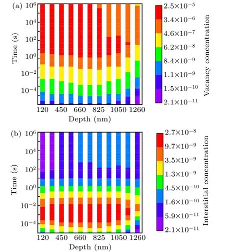
Fig.3. The evolution of(a)vacancy concentration and(b)interstitial atom concentration over time with implanted ions.
Considering the implanted ion effect in CD calculation,the evolution of point defect concentration is shown in Fig.3.Figures 3(a) and 3(b) respectively show the evolution of vacancy and interstitial atom concentration with time at 11 depths. Compared with Fig. 2, between the original stage of interstitial atoms being captured by the sink and the later stage of vacancies being captured by the sink, there is a brief period where Ciincreases and Cvdecreases. The greater the ion injection rate at the corresponding depth,the more significant change in point defect concentration. Specifically,Ciand Cvat depth of 120 nm has no significant change because of the lowest ion implantation rate.
In the previous stage, the magnitude of the ion injection rate is ~10−8, which is less than the initial capture rate of interstitial atoms by sink, so the capture of interstitial atoms by sink is still dominant. As Cidecreases, the capture rate of interstitial atoms by sink also decreases, which could drop to less than the ion injection rate. Then, at this stage, the implanted ion effect plays a dominant role in the evolution of the point defect concentration, and there is an increase in the Ciwith a decrease in the Cv. However,due to the increase of Ciat this stage,the capture of sink to interstitial atoms increases accordingly to compensate for the change caused by the ion injection rate. Finally,it comes to the stage where the capture of vacancy by the sink is dominant.
4. Discussion on point defect concentration
Comparing the steady-state point defect concentration distribution in the above two cases,the difference between Cvand Ciare shown in Figs. 4(a) and 4(b), respectively. When the ion implantation effect is not considered, the depth distribution of the point defect concentration is consistent with that of damage rate. It increases first and then decreases with the peak at 825 nm. The change of point defect concentration with depth is more gradual than damage rate. From 120 nm to 825 nm, the damage rate increased by about 1.5 times, while the point defect concentration increased by only 0.6 times.The depth distribution of the point defect concentration calculated by cluster dynamics is smoother than the displacement damage distribution calculated by SRIM.
When compared the results of CD calculation with the results obtained by simplifying the point defect balance equation in Fig. 1(b), it can be found that their point defect concentration follow a consistent depth distribution, and remain the same magnitude. Without considering the effect of implanted ions, the point defect concentration under irradiation can be quickly estimated by simplified solution of point defect balance equation.
After considering the ion implantation effect, the point defect concentration distribution has changed significantly.Cvdecreases with the depth significantly,while Cifirst increases and then decreases with the depth change with peak at 990 nm.The higher is the ion implantation rate at the corresponding depth,the more significant decrease does Cvshow. Cihas increased to various degrees, and it increases significantly with the higher ion implantation rate. At 120 nm,Cvdecreases by about 0.8%,and Ciincreases by only 0.7%. While at 990 nm,Cvdecreases by 86%,Cishows the maximum interstitial atom concentration increased by nearly 6.2 times.
The curve of vacancy concentration difference (denoted as ΔCv)between the two cases shows the distribution of ΔCvis closer to the damage rate distribution,which is quite different from the ion implantation rate curve. Similarly, for interstitial atom, the difference of interstitial concentration is closer to the interstitial concentration with ion implantation, that is,ion implantation rate distribution. In the simulation of Short et al.,[18]it was also observed that the concentration of interstitial atoms increased and the concentration of vacancies decreased due to the injected interstitial effects.While the depth distribution of point defect is still consistent with displacement damage. In Fig. 4(a), the vacancy concentration decreases with the depth significantly,which may be due to the selected small radiation dose.
According to Shao et al.,[14]voids developed first in the near-surface lower-dose region and then develop at progressively deeper and higher-damage depths during continued irradiation. With increasing dpa values,not only the void sizes increase, but the void distributions become wider, moving deeper into the specimen. In total,the higher implant ion concentration has a significant impact on the final point defect concentration during the irradiation process.

Fig.4.(a)The influence of implanted ions on the vacancy concentration and(b)interstitial atom concentration.
The depth distribution of the vacancy concentration when considering the ion implantation effect is comparable to Refs. [14,17]. Shao et al.[14]used 3.5-MeV self-ion irradiation to study the effect of defect imbalance on void swelling.Applying the BTE method, they predicted an interstitial-rich region near the ion’s projected range. As a result, the void swelling distribution deviates significantly from that expected from the dpa profile.The same phenomenon was observed that the void swelling by cross sectional TEM characterization was suppressed at the peak dpa region. For the 35-dpa irradiation,swelling appears at a peak depth about 200-nm beneath the surface, and decreases down to zero at a depth of ~0.8 µm.Swelling increases with increasing dpa at shallow depth and the trend reverses at deeper depth. At 105 dpa,there is still a total suppression corresponding to the majority of injected interstitial region. The swelling distributions for irradiation are calculated shallower than that of the dpa profile.
In the study of void swelling evolution in self-ion irradiated HT9, Getto et al.[17]also observed a decrease in void swelling at depths greater than the nominal dose,attributing to the presence of injected interstitials. Short et al.[28]simulated injected interstitial effects on void swelling in self-ion irradiation experiments and predicted a double peak in the void nucleation rate. The double peak may be due to the surface effect, which is not considered in the SRIM simulation. The value of vacancy migration energy will also affect the behavior of void nucleation rate curve. However,the model selected in this article is space-independent and not related with vacancy migration energy.
Sun et al.[29]studied the void swelling in two structural variants of 304L stainless steel induced by self-ion irradiation at 500°C.A prominent suppression of void density in the injected interstitial region was observed, which was consistent with what Getto et al.[17]observed. In addition, there was a clear forward shift in depth between the peak dpa and the peak void swelling in both variants,due to suppression of void nucleation by injected interstitials. Furthermore, α′particles were not only observed under neutron irradiation. Tissot et al.[30]firstly observed α′precipitation in Fe–Cr alloys under self-ion irradiation. The absence of α′precipitates in previous ion irradiation experiments is attributed to the presence of a high concentration of injected interstitials. Therefore,when using ion irradiation to simulate neutron irradiation, the effect of injected interstitial cannot be ignored, especially microstructures at peak damage is investigated for irradiation effects at high doses.
5. Conclusion
In this paper,cluster dynamics simulation is used to study the effect of ion implantation on point defect concentration under 2.8-MeV iron self-ion irradiation at 290°C.When considering the effect of implanted ions,before entering the final steady state, Ciand Cvshow a significant increase and decrease, respectively. At the peak depth of ion implantation rate, the Cvdropped by 86%, and Ciincreased by 6.2 times.With the evolution of point defect concentration,the injection of ions can have a significant effect on the concentration of point defects at high doses of heavy ion irradiation. Therefore,the effect of injected interstitials on the evolution of matrix damage can be simulated by cluster dynamics to better understand the heavy ion irradiation experimental results.
Acknowledgment
We are grateful to the support by Key Laboratory of Particle Technology and Radiation Imaging,Ministry of Education of China.

- Chinese Physics B的其它文章
- Process modeling gas atomization of close-coupled ring-hole nozzle for 316L stainless steel powder production*
- A 532 nm molecular iodine optical frequency standard based on modulation transfer spectroscopy*
- High-throughput identification of one-dimensional atomic wires and first principles calculations of their electronic states*
- Effect of tellurium(Te4+)irradiation on microstructure and associated irradiation-induced hardening*
- Effect of helium concentration on irradiation damage of Fe-ion irradiated SIMP steel at 300 °C and 450 °C*
- Optical spectroscopy study of damage evolution in 6H-SiC by H+2 implantation*