
A method to determine the shell layout scheme for equipment battlefield damage tests under artillery fire
2021-03-23 14:00:52CiChenQunShiZhifengYouHongyuGeFngZhng
Defence Technology 2021年2期
Ci Chen ,Qun Shi ,Zhi-feng You ,Hong-yu Ge ,Fng Zhng
a Equipment Command and Management Department,Army Engineering University,Shijiazhuang,050003,China
b Baicheng Ordnance Test Center of China,Baicheng,137001,China
c No.32178 Troops of PLA,Beijing,100012,China
Keywords:Battlefield damage test Projectile impact point Effective damage area Functional damage
ABSTRACT In this paper,a new method for determining the shell layout scheme is proposed,which can make the equipment damage data by the battlefield damage test resemble as close as possible the actual combat data.This method is based on the analysis of the impact point distribution and effective damage area of equipment.In order to obtain the position of the impact points,an impact point distribution model under artillery fire was established.Similarly,in order to obtain the effective damage area of equipment,the concepts of generalized damage area and task-based equipment functional damage probability were demonstrated,and the corresponding calculation model was established.Through case analysis,the shell layout scheme was effectively obtained,verifying the correctness of the proposed method.
1.Introduction
To effectively improve the maintenance capability of equipment during wartime and enhance the lifespan of equipment on the battlefield,training schemes during peacetime should be based on equipment damage data close to actual combat conditions[1].At present,the equipment battlefield damage test is the only way to obtain equipment battlefield damage data in peacetime.This is typically a collection of either static or dynamic detonation tests depending on the state of the shell as it explodes.Static detonation tests are usually performed by placing the shell on a bracket at a certain height,deploying equipment targets around it,and manually detonating the shell.At the same time,damage data of the equipment is collected.In contrast,dynamic detonation tests use a fuse to detonate the shell inside a designated target area through actual firing or throwing.
Static detonation tests are often used since they are relatively simple to implement,and the cost and risks are relatively low.In addition,the layout of shells and targets are specified in relevant test standards[2-4].Shi[5]detailed a static detonation test scheme,including preliminary preparation prior to the test and the specific implementation process,and analyzed relative positions between target and shell.Wang[6]improved upon the static detonation test method and studied the dispersion of fragments of a large equivalent warhead weight.Further to this,another study set equivalent targets at different directions and at various distances around a static bomb blast and collected damage data to evaluate the comprehensive power of the high-explosive shell[7].
In all of these studies,the relative positions between shell,target,and equipment were predefined and analyses were highly subjective and qualitative in nature.Test data obtained in this way differs greatly from the dynamic conditions of an actual combat environment,and thus cannot meet the requirements for training troops in an actual combat environment.To this end,the dynamic detonation test is a better choice of equipment battlefield damage test.However,the impact area and burst time of the shell are difficult to control,which inevitably increases the costs and risks associated with dynamic testing.Therefore,dynamic detonation tests are mostly theoretical and few actual test cases have been examined.Dai[8]obtained the dynamic dispersion characteristics of fragments by analyzing their dispersion under static explosions and simulated the damage effectiveness of shell fire on a light armored vehicle under a dynamic attack.Gao[9]and Yin[10]adopted a numerical simulation method based on the analysis of static explosion characteristics of ammunition.Fragments were assigned an initial velocity along the flight direction of the shell,which was the flight velocity of the shell at the initial moment of the explosion,to simulate the dynamic explosion of a shell.
This paper proposes a new method for determining the quantity and distribution of shell during the equipment battlefield damage test by analyzing the distribution of impact points and the equipment effective damage area.The proposed method truly reflects the relative positions of the shells and equipment under actual combat conditions,and the damage data obtained in the test is much closer to the actual battlefield situation.Thus,the method provides an important reference and has guiding significance for the overall design of equipment battlefield damage test schemes.It should be mentioned that since the fragment is the main destruction mode after shell explosion,this paper focuses on analyzing the determination method for the equipment effective damage area under fragment attack.If the effect of shock wave or shock vibration on the equipment effective damage area is considered,the analytical method can be compared with that under the effect of fragment.
2.Principle for determining shell layout scheme
In actual combat,the equipment is usually deployed in a cluster.When a cluster of equipment is attacked by artillery fire,all of the equipment is considered as the target of the attack,since an attack on a single piece of equipment is unlikely.Therefore,in actual combat,the positions of shells are scattered.However,owing to the cost of using an entire group of equipment,only one or two pieces of equipment can be used in the test.Moreover,not all shells cause damage to the equipment at the same time.To achieve test results consistent with actual combat situations and reduce the cost of the test,the impact points that can effectively damage the equipment should be identified,and then be taken as a reference to determine the quantity of shell and its relative position with respect to the equipment in the test.Therefore,this paper proposes the concept of the effective damage area,and analyzes the law of impact point distribution,aiming to determine the impact points that can effectively damage the equipment.The specific analysis steps are as follows:
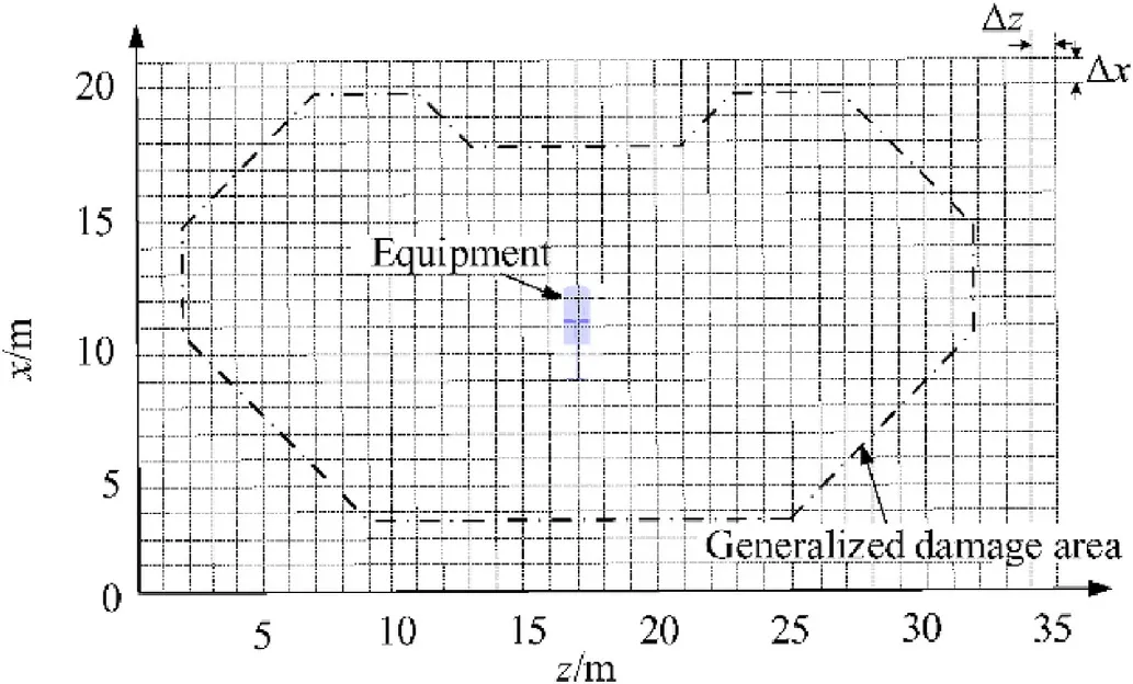
(1)Analysis on the law of impact point distribution.As shown in Fig.1(a),a certain equipment group is taken as the target and the Monte Carlo method is used to simulate artillery fire on the equipment,which can provide the coordinates of the impact points.
(2)Determine the effective damage area of equipment.As shown in Fig.1(b),the effective damage area refers to the area where the shell can cause functional damage to the equipment,and its size and shape is dependent on equipment type,warhead type,and test requirements.The shell can cause functional damage to the equipment when it falls within the effective damage area.When it falls outside the effective damage area,it is considered that the shell cannot cause functional damage to the equipment.
(3)Determine the shell layout scheme set.As shown in Fig.1(c),the shell quantity and impact point coordinates can be obtained from a single simulation,which can be selected as the shell layout scheme of the equipment battlefield damage test.Based on the actual requirements,multiple simulations can be performed to obtain the set of all possible shell layout schemes.It should be mentioned that if the shell hits directly the equipment,the damage data collected is of little significance to maintenance training.Therefore,the shell layout scheme set in this paper does not incorporate impact points that hit the equipment directly.
3.Analysis of artillery fire impact points
The determination of impact point distribution under artillery fire is the basis for determining the shell layout scheme.Based on the firing error analysis,the Monte Carlo method is employed to analyze the impact points of artillery fire.
3.1.Effect of firing error on impact point distribution
In the theory of artillery fire,deviation of an impact point relative to the aiming mark is called firing error and can directly affect the distribution of impact points under different firing conditions.To conveniently investigate impact point distribution under different conditions,it is necessary to first group the firing errors.This grouping is mainly based on the performance and quantity of artillery,method of firing or aiming,and characteristics of the error source[11].In the random error case,the error caused by the same error source is called common error,while the error caused by each individual error source is called individual error.This paper considers an artillery battalion as the object of analysis,and the firing errors are divided into four groups:battalion common error,battery individual error,artillery individual error,and dispersion error.The battalion common error has the same effect on the dispersion center of each battery;the battery individual error is when the error between different batteries is different;the artillery individual error makes the error between different artilleries different;and the dispersion error is when the error of each artillery is different at each launch.
The firing error diagram of an artillery battalion is shown in Fig.2,where the origin O is the aiming mark,the depth is along xaxis,and the direction of the left-right deviation is along the z-axis.
Assuming that the firing position of each battery is relatively close,the battalion common error of each battery can be taken to have approximately the same value[12].During firing,under the effect of the battalion common error,the dispersion center of each battery deviates from point O by the same offsetand moves to CY.Under the effect of the battery individual error,the dispersion center of the battery deviates from CYby the same offsetand moves to CL.Under the effect of the artillery individual error,the dispersion center of each artillery deviates from CLby the same offsetand moves to CP.Under the effect of the dispersion error,the impact point deviates from CPby the same offsetand moves to Z.Therefore,according to the vector relationship illustrated in Fig.2,the firing error of the artillery battalion can be determined by
3.2.Basic concept of impact point simulation
The four types of artillery battalion firing errors are independent of each other but all follow a normal distribution.Through the Box-Muller algorithm,the random number of a normal distribution obeying an N(0,1)distribution can be obtained as follows[12]:


Fig.1.Principles for determining the equipment damage test scheme.
where w1and w2are a pair of standard normally distributed random numbers;φ1andφ2are random numbers that follow a uniform distribution U(0,1).

Fig.2.Schematic diagram of the firing error of artillery battalion.
In this paper,the analysis of the impact point simulation method is based on the battalion fire distribution of a converged sheaf and one-range fire.In the artillery battalion,M batteries exist,each battery has N artilleries,and each artillery can fire Q rounds.To obtain the shell coordinates(xijk,zijk)of artillery j in battery i of the artillery battalion after the k-th firing,the range and direction mean errors of the battalion common error are set as Exyand Ezy,i=1,2,…,M;j=1,2,…,N;k=1,2,…,Q.The target area is 2lz×2lxand the aiming mark is the target center O(x0,z0).Then,the dispersion center(xy,zy)of the artillery battalion can be expressed as:

whereρis a normal constant with a value of 0.476936[13].In the same way,the range and direction mean errors of the individual error of battery i are set as Exiand Ezi.Then,the dispersion center(xi,zi)of battery i can be expressed as:

The dispersion center(xij,zij)of artillery j can be obtained according to the dispersion center(xi,zi)of battery i and the firing data error Exijand Ezijof artillery j.The coordinate of impact point(xijk,zijk)of the k-th firing can be obtained according to the dispersion center(xij,zij)of artillery j and the mean errors Bdijand Bfijof the dispersion error.In the calculation process,w1and w2are sampled and calculated using Eq.(1).
3.3.Impact point simulation of typical fire distribution
Fire distribution refers to the specific firing position of each artillery;that is,whether the artillery battalion chooses overlapping firing or sweeping firing,whether the artillery battery chooses converged sheaf or parallel sheaf,or whether one-range fire or zone fire is selected.In this paper,the impact points of the battalion are simulated with overlapping firing under different fire distributions along the front and depth.When sweeping firing is used,the simulation method is similar to that for overlapping firing.
3.3.1.Impact point simulation of frontal fire distribution
In frontal fire distribution,the firing direction is an important concept,referring to the direction each artillery piece is fired toward the front of the target.Regardless of the number of artillery participating in the fire,the firing direction is based on the artillery battery as a unit and can be divided into converged sheaf or parallel sheaf.Converged sheaf refers to when the whole artillery of the battery fires toward a certain area of the target.Parallel sheaf refers to when the target is divided into several segments equal to the number of artillery in the artillery battery,and each artillery fires at the center of its assigned segment with a certain order.The simulation steps for the converged sheaf scenario are the same as those described in Section 4.2.The method for simulating impact points distribution under the parallel sheaf scenario is analyzed below.
According to the dispersion center(xi,zi)of battery i,the aiming mark of artillery j is set as,j=1,2,…,N,where N is the quantity of artillery in the battery.Substituting the coordinates of the aiming mark of artillery j and its firing data errors Exijand Ezijinto Eq.(2),the dispersion center(xij,zij)of artillery j can be obtained.Then,the coordinates of the impact point can be obtained by following the steps described in Section 4.2.
3.3.2.Impact point simulation s for depth fire distribution
The depth fire distribution includes one-range fire and zone fire.One-range fire is defined as only firing on the battery’s central rule.Zone fire refers to batteries alternating fire at far,middle,and near distances,thereby forming a larger depth of firepower coverage.When the range difference is Hx,the dispersion center of artillery j of battery i can be expressed as(xij+r·Hx,zij),r=-1,0,1.On this basis and according to the mean error of dispersion,the position of the impact points under zone fire can be obtained.
3.4.Calculation process
A program was written in MATLAB(version R2014a)to simulate the impact point distribution of a typical artillery fire arrangement based on the simulation model of impact points established in Sections 4.2 and 4.3.A flowchart of the calculation process is presented in Fig.3.
4.Equipment effective damage area
4.1.Analysis of effective damage area
As shown in Fig.4,the test site area is assumed to be 2Lf×2Ld.According to the accuracy and precision requirements of the test,the test site can be divided into a grid-like pattern by drawing lines parallel to the two coordinate axes with spacings ofΔx andΔz.
The mesh vertex C of row j and column i can be considered as the centroid of the equipment(i=1,2,3,…,m,j=1,2,3,…,n),where m and n are the maximum number of grids along the two axes.The effective damage area of equipment S1can be defined as:

where Phk(z,x)is the conditional probability of equipment functional damage caused by fragments of the test shell at any point(zi,xj)on the test site.The value of Phk(z,x)is clearly related to the intensity of the damage factors and the structure and strength of the target equipment.The former depends on the damage effectiveness of the fragment,whereas the latter depends on the structural design and performance characteristics of the equipment itself.The most direct manifestation of fragment damage effectiveness is the physical damage caused to the external structure of equipment,such as perforation and deformation.
The functional damage can be analyzed by combining the physical damage with the structural and performance characteristics of different types of equipment.Thus,the probability Phk(z,x)can be decomposed into:
where P(KΔzΔx|H)is the conditional probability of physical damage to the equipment caused by the shell after an explosion in the area ΔzΔx and represents the strength of the fragment damage effectiveness;P(K|KΔzΔx)is the conditional probability that the physical damage is transformed into functional damage,if physical damage has occurred,and reflects attributes of the equipment,such as its structure and performance.Then,Eq.(4)can be transformed into:
The concept of a generalized damage area SΔis introduced.Unlike the effective damage area S1,the range of the generalized damage area is wider.As long as the shell can cause physical damage to the equipment after an explosion at any point(zi,xj),the areaΔzΔx near the point(zi,xj)is included in the generalized damage area SΔwithout considering whether the physical damage has affected the performance of the equipment.Physical damage to equipment components does not necessarily cause functional damage to the equipment,therefore,the effective damage area S1belongs to the generalized damage area SΔ,and the relationship between them is illustrated in Fig.5.
Then,Eq.(6)can be transformed into:

and

Eq.(7)shows that if the generalized damage area SΔis known,the effective damage area can be determined,as long as the functional damage probability can be obtained.Therefore,the key to determining the effective damage area is to first determine the generalized damage area,and then quantitatively analyze the functional damage probability of the equipment.
4.2.Generalized damage area
To determine the generalized damage area,a large number of equipment damage data generated by a fragment attack are required.A simulation platform for equipment battlefield damage can be used to obtain this data.

Fig.3.Flowchart of the simulation for determining the impact point distribution.
4.2.1.Battlefield damage data collection
An equipment battlefield damage simulation platform was developed as the basis for obtaining damage data and consists of four modules:a threat information module,an environment information module,an equipment information module,and a damage simulation module.Each module contains different components.The framework is illustrated in Fig.6.
When simulating the impact of fragments on a single piece of equipment,the simulation is accomplished through the following steps[14]:
(1)Simulate the fragment penetration process;
(2)Simulate the damage to the basic geometric elements of the equipment;
(3)Simulate the damage to the basic units of the equipment;
(4)Simulate the damage to the entire equipment.
The simulation of the fragment penetration process mainly involves first the simulation of the fragment formation process,followed by the fragment trajectory,and finally,the fragmentequipment impact process.Furthermore,simulating the damage to the basic geometric elements mainly involves simulating the damage process of fragments to basic geometric elements of the equipment.The damage results can then be analyzed and summarized.Simulating the damage to the basic units of the equipment involves collecting and analyzing damage data,which are related to the basic units of the equipment.Simulating the damage to the whole piece of equipment involves analyzing the damage data with emphasis on the whole equipment damage.This was carried out by following the first three steps presented above.By implementing four separate simulation processes,the platform can output fragment field distributions for different types of ammunition.A virtual prototype of the equipment was established such that coupling effects between fragments and components could be incorporated,and the process was reproduced as a threedimensional visualization(Fig.7).Finally,the damage situation,damage mode,and damage degree in each part of the equipment were obtained.

Fig.4.Schematic diagram of the simulated artillery fire test site.

Fig.5.Relationship between the two types of damage area.
4.2.2.Damage data analysis
After obtaining the damage data,the generalized damage area of the equipment was calculated by hypothesis testing.When the distance between the explosion point and the equipment is Lt,the hypothesis H0:μt=0 is tested with a significance levelα,whereμtindicates the total number of fragments that hit the equipment at the location of the explosion t,andμt=0 indicates that no fragments hit the equipment.
A total of p explosion points around the equipment were set and the distance between each explosion point and the equipment was Ln(n=1,2,…,p);q simulations were performed at each explosion point,and Xn1,Xn2,…,Xnq,Xniwere obtained,indicating the total number of fragments that hit the equipment at explosion point n during simulation i.The variable was constructed as:

conforming to a t(q-1)distribution,where:
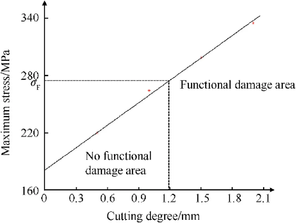
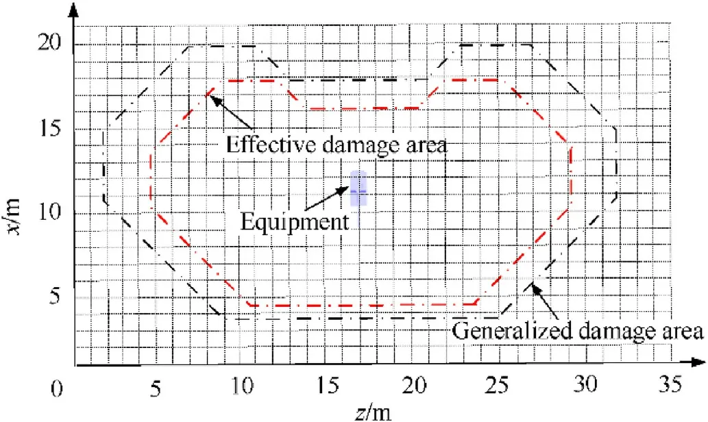
For a given significance levelα,ifthe hypothesis H0is rejected;that is,there is a significant difference between the total mean and zero,which indicates that the distance Ltat explosion point t is an effective killing distance;if-0| In actual combat,the judgment criteria for whether functional damage occurs may differ,owing to the various combat tasks undertaken.For example,a radar tire may be hit and scraped during a combat mission,and although its motion function is damaged,if the antenna remains intact,the radar tire can still perform other functions such as search and positioning.In battlefield damage testing,damage data related to one or several functions of the equipment are collected,whereas damage data related to other functions are considered relatively minor or ignored altogether.This paper puts forward the concept of task-based equipment functional damage probability from the perspective of equipment completing a specific task.Therefore,the task-based equipment functional damage probability Ptcan be defined as: where neis the quantity of basic equipment items,which has been previously defined in the literature[15];awis the assignment coefficient of basic items determined for specific tasks;if basic item w has an impact on the task,aw=1;otherwise,aw=0;Pwis the functional damage probability corresponding to basic item w.Assuming that the simulation runs Netimes,we can obtain: where Pwvis the functional damage probability of basic item w of the v-th simulation.To determine the probability Pwv,the structural characteristics and operational mechanisms of the various basic items must be first combined and then those subjected to physical damage should be analyzed by constructing a simulation model.Finally,the simulation results and damage criteria are used to determine whether the basic items have functional damage in order to obtain the probability of functional damage. Fig.6.Framework of the battlefield damage simulation platform. Fig.7.Visualization of the simulated physical damage. Assuming that a howitzer battalion shoots a self-pro pelled artillery formation in a 300 m×300 m rectangular area with a firing distance of D=7000 m and third charge,then the mean values ofeach error source can be determined for each element using the precision method,while the dispersion mean errors can be found in the ballistics table[13].The various error values are listed in Table 1. Table 1Mean error values for each error source. Fig.8.Impact points distribution. Battalion fire uses parallel sheaf and zone fire.The range difference Hx=100 m.In the simulations,a total of 432 shells were fired and the impact point distribution is shown in Fig.8. Based on the analysis presented in Section 5,it is necessary to first analyze and calculate the generalized damage area and the probability of equipment functional damage before obtaining the equipment effective damage area. 5.2.1.Equipment generalized damage area To determine whether the areaΔzΔx near the burst point(zi,xj)is within the generalized damage area,it is necessary to deploy a number of burst points around the equipment following the method presented in Fig.4.Then,the number of fragments that hit each component of the equipment after the explosion of a shell at different burst points can be calculated.The generalized damage area can be obtained using the hypothesis testing method described in Section 5.2.In the case study,the generalized damage area was determined with a total area of 388 m2,as shown in Fig.9,where the interval between burst points was 1 m. Fig.9.Schematic diagram of the generalized damage area. 5.2.2.Analysis of functional damage probability Assuming that the main task is to collect damage data from the artillery transmission system,Eq.(11)shows that only the functional damage probability analysis is required for the artillery transmission system.Taking the gearbox as an example,the damage mode is mainly cutting off the surface of a gear tooth according to the physical damage simulation results of the equipment battlefield damage simulation platform.Thus,a tooth surface cutting simulation model can be developed,as shown in Fig.10. Fig.10.Model of tooth surface cutting. Cutting off of the gear tooth surface will affect the stress distribution in critical sections of the gear tooth.When the cutting damage reaches a critical level,the stress in critical sections of the gear tooth will be larger than the allowable bending stress of the gear tooth.In general,the allowable bending stress can be obtained experimentally,and the empirical expression is: whereσFlimis the tooth root bending fatigue limit,SFminis the minimum safety coefficient of bending fatigue strength,YNis the life coefficient,and YXis the dimension coefficient.By looking up the values in published in Ref.[16],specific values of the four parameters were obtained,which are listed in Table 2.Substituting these values into Eq.(13),the allowable bending stressσFof the gear tooth was obtained as 278 MPa. Table 2Parameters at the permissible bending stress. The Adams 2017(MSC)software was used to model the motion of the gearbox and the maximum stressσmaxat the root of the tooth under different cutting degrees was obtained.When the stressσmaxexceedsσF,the gear tooth will fracture causing functional damage to the gearbox.Based on this criterion,a functional damage diagram of the gear tooth was obtained,as shown in Fig.11. Fig.11.Functional damage diagram of the gear tooth. Repeating the simulation process 20 times,the functional damage probability of the gearbox was calculated using Eq.(12)as 0.60.Similarly,the functional damage probability of other components in the transmission system can be obtained.The functional damage probability of the artillery was also obtained for the particular task using Eq.(11)as 0.71. After the generalized damage area and functional damage probability of the artillery were determined,the effective damage area was calculated using Eq.(7)as 275.48 m2,and a schematic illustration of the effective damage area is presented in Fig.12.If the shell is deployed within the effective damage area,damage data that meet the requirements of the task can be successfully collected. Fig.12.Schematic diagram of the effective damage area. A total of six self-propelled artillery were configured on a 300 m×300 m rectangular area.Artillery were placed 50 m apart from left to right with a depth of 80 m and were numbered consecutively.Using the method described in Section 5.1 for firing the target position,the distribution of impact points around the equipment was obtained,as shown in Fig.13. To formulate the test scheme,equipment No.2(Fig.13)was used as the reference object and the coordinates of the impact points within the effective area were set as Ai(xi,yi),where i=1,2,3,…,s,and s is the quantity of the shell.As shown in Fig.14,the quantity and coordinates of the impact points,which were within the effective damage area,were obtained using the effective damage area,which can be considered a reference scheme for the shell layout.The specific coordinate values of the shells are listed in Table 3. Fig.13.Equipment configuration and impact point distribution. Fig.14.Schematic diagram of the impact points within the effective damage area. Table 3Shells coordinates within the effective damage area of equipment No.2. In this way,multiple shell layout schemes can be obtained through multiple simulations and a set of shell layout schemes for the equipment battlefield damage test can be established.According to test requirements,the operator simply chooses the best scheme from the scheme set,such that the total test efficiency is optimal. To address a lack of theor etical references for determining the shell layout for the equipment battlefield damage test,this paper puts forward a new idea that combines the analysis of impact point distribution with the effective damage area.Moreover,the proposed method solves the problem of inconsistencies between data collected experimentally and actual combat data.First,an impact point model under artillery fire was established and the effect of firing error and different fire distribution patterns on the impact points were analyzed.The distribution of impact points and the location of shell fragments were obtained using Monte Carlo simulations.Then,a model of the effective damage area was established.Furthermore,the concepts of a generalized damage area and functional damage probability were demonstrated,and their calculation methods were analyzed.Finally,a case study was performed using various simulation platforms,and a set of all shell layout schemes for the battlefield damage test was obtained,showing that the new approach for determining shell layout schemes is feasible and potentially has reference value for engineering applications. Foundation items Key projects of pre-research fund(No.9140A27040414JB34001). Declaration of competing interest The authors declare that they have no known competing financial interests or personal relationships that could have appeared to influence the work reported in this paper.4.3.Quantitative analysis of the equipment functional damage probability


5.Case analysis
5.1.Shell impact point simulation


5.2.Equipment effective damage area


5.3.Definition of the shell layout scheme


6.Conclusions

- Defence Technology的其它文章
- Defence Technology
- Combustion of B4C/KNO3 binary pyrotechnic system
- A novel launch dynamics measurement system for multiple launch rocket system and comparative analysis with numerical simulations
- Automated integration of real-time and non-real-time defense systems
- Preparation and characterization of HMX/EVA/hBNNSs microcomposites with improved thermal stability and reduced sensitivity
- Quasi-steady aerodynamic characteristics of Terminal Sensitive Bullets with short cylindrical portion