Four-port hydraulic transformer with inlet and outlet equal flow and its pressure transformation ratiocharacteristics
Lian-quan ZHOU,Qiang LIU*,Cheng-qiang LIU,Xiao-nan BO,Chu ZHANG
(1 Jiangsu Normal University,Tongshan Borough,Xuzhou 221116,China)
(2 Xuzhou University of Technology,Yunlong Borough,Xuzhou 221116,China)
Abstract:In order to avoid throttling loss and recover differential pressure energy,braking energy and gravitational potential energy without changing the original hydraulic system,the four-port hydraulic transformer with inlet and outlet equal flow(FHT),which can be directly connected to the original hydraulic system,is proposed.First,the basic structure and principle of the FHT are explained,themain characteristic of FHT is that there are four waist shape slots of the same size and shape in the valve plate,and the pressure ratio can be changed by adjusting the control angle of the valve plate,and the flow rate of port A is the same as port B,the combination of port A and B is equivalent to a hydraulicmotor,the flow rate of portO is the same as port T,and the combination of port O and T is equivalent to a hydraulic pump.Then,the mathematical models of displacement,angular torque and pressure transformation ratio about the four-porthydraulic transformer are built.Moreover,the relationship between pressure transformation ratio and flow of the low-pressure port,recycling pressure difference and oil viscosity are obtained by using themethod of partial derivation,based on this,the influence characteristics of the three factors on pressure transformation ratio are got by MATLAB simulation.Finally,the result of theoretical analysis and simulation shows the increase in flow rate of load circuit results in decreasing the pressure transformation ratio,while the decrease of oil viscosity and the increment of recycling pressure difference result in increasing pressure transformation ratio.
Key words:Hydraulic transformer,Pressure ratio,Load flow circuit,Oil viscosity,Recycling pressure difference
Existing hydraulic equipment usually uses circuits with fewer pumps and more loads,the output pressure of the hydraulic pump must be higher than the maximum load pressure tomake themaximum load action.If the load pressure varies greatly,then the oil supplied by the system to the low-pressure load loop would be throttled off by the speed control valve and resulting in large power loss.In this case,the efficiency of the system is low,while the oil temperature is raised,To reduce the oil temperature to the required range of the system,itmust be equipped with high-power cooling equipmentwhich increase the power consumption.Under conditions of potential energy reduction and inertial kinetic energy braking,the potential energy and kinetic energy are also converted into thermal energy through throttling.
Nowadays,themajority of the hydraulic equipment,especially engineeringmachinery,are valve-controlled load hydraulic system,which can adjust the load speed through throttling.This kind of system are very mature.Many of them have been made into integrated valves and industrial hydraulic pumps tomatch specific load.It is difficult to change the structure and process of the existing hydraulic system.Because of the problems of throttling,heating and inefficiency[1-2],a liquid energy recovery and energy saving device are needed.When the energy-saving device is stringed into the load loop,which has regulated the flow rate,the pressure above the load is recovered to reduce the throttling loss of the hydraulic system.
When two pumps/motors are connected together rigidly with a shaft being the traditional hydraulic energy recovery device,the structure become relatively complex,with large volume and weight,low recovery efficiency,and highcost.A new type of three-port hydraulic transformer has 3 ports in valve plate(A,B,T),the pressure ratio is defined as the ratio of port B to port A pressure,and the flow rate ratio of port B to A is the reciprocal of the pressure ratio of transformer.If port A and port B of the new three-port hydraulic transformers are connected into the hydraulic load loop,then the pressure of the load loop changes with the working condition,the flow would be regulated by the flow control valve.After the hydraulic transformer,the flow output from port B is no longer constant,but changeswith the working condition.It is difficult to control the flow into the load.When multiple loads flow at the same time,the operation of the main engine become very poor,and even cause accidents.Therefore,the new three-port hydraulic transformer is mainly used for the secondary pressure regulation of the common pressure rail,and it cannotbe used in series to recover the differential pressure liquid energy in the circuit[3-7].
Therefore,for the existing valve-controlled hydraulic system,a plunger-type four-port hydraulic transformer with inlet and outlet equal flow is proposed.Without changing the current speed regulationmode of valve-controlled load,it can recover the hydraulic energy wasted by throttling in the original system.The FHT can directly utilize the recovered hydraulic energy and store the energy.When the system requires high-pressure oil,the hydraulic transformer can release the stored energy back into the system.With the application of hydraulic transformer,the hydraulic system’s efficiency can be improved,the loss of liquid energy is greatly reduced,the system heating and oil temperature rise are reduced,the cooling device specifications of the system are reduced,the installed power of the system can also be reduced.
The pressure transformation ratio characteristics of the plunger-type four-port hydraulic transformer are studied in this paper.It is of great significance to provide theoretical basis for the design of hydraulic transformers as the mathematicalmodel of pressure transformation ratio is established and influence factors of pressure ratio are analyzed,simulating by MATLAB software.
1 Plunger-type four-port hydraulic transformer w ith inlet and outlet equal flow
1.1 Structure and principle of the FHT
The plunger-type four-port hydraulic transformer with inlet and outlet equal flow is shown in Fig.1,it ismainly composed of end cover,valve plate,cylinder block,plunger,driving plate and shell.Four-port hydraulic transformers are the same as the inclined axial column motors except the end cover and the valve plate[8].
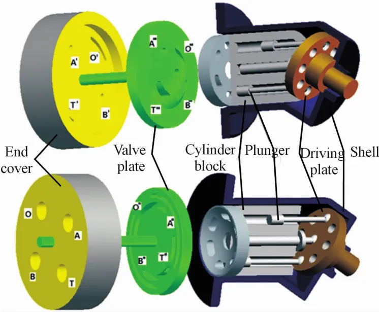
Fig.1 Structure diagram of four hyd rau Iic transformers
The right end face of the end cover and the left end face of the valve plate are bonded by oil film,the spherical surface at the right end of the valve plate and the spherical surface at the leftend of the cylinder block are the same.The left end of the cover has four oil ports A(high pressure oil inlet),B(low pressure oil outlet),O(recovery oil outlet)and T(low pressure oil suction port),there are four kidney-shaped holes A′,B′,O′and T′at the right end of the cover,A,B,O and T are connected with A′,B′,O′and T′,respectively.The positions of A′and O′are relative to the positions of B′and T′,respectively.
The left end of the valve plate has four kidneyshaped holes A″,B″,O″and T″,along the center axis,there are four kidney-shaped holes A‴,B‴,O‴and T‴with the same size in the right end of the valve plate,A″and A‴,B″and B‴,O″and O‴,T″and T‴are connected through a diagonal hole,respectively.The cross section area between A″and A‴,B″and B‴,O″and O‴,T″and T‴are equal.The position of A,O,A″and O″are relative to the position of B,T,B″and T″,respectively.The centerline of A′,B′,A″and B″lie on the same cylinder surface.The centerline of O′,T′,O″and T″lie on the same cylinder surface,the two cylindrical surfaces are coaxial and vary in radius.
Within the rotational range of the valve plate,A′,B′,O′and T′are connected to A″,B″,O″and T″through overlapping ways,respectively.A′,B′,O′and T′will not be obscured by A″,B″,O″and T″.
Similar to three-port hydraulic transformers,the maximum stroke and maximum retractable stroke of the plunger are defined through the drive plate,when the plunger reaches the maximum stroke position,its circumferential position on the end cover is defined as the top dead center(TDC),when the plunger reaches the minimum stroke,its circumferential position on the end cover is defined as the bottom dead center(BDC).
Based on the above description,the connecting ports of the left end oil port of the end cover and the right-side kidney-shaped hole of the valve plate are as follows.
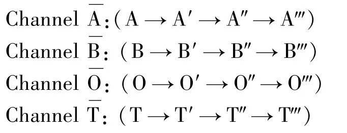
Assuming port A is the high-pressure inlet,port B is the low-pressure outlet(connecting load),portO is the recovery outlet and port T is the low-pressure suction outlet,in this case,the working process of the FHT is as follows.
(1)When high pressure oil is connected to port A,it flows into the plunger hole connected with A‴through the channeland exerts force on the plunger to extend out of the plunger hole,at the same time,the force acts on the driving plate through the plunger rod and generates a torque,which makes the driving plate rotate.Depending on the touch between the connecting rod and the innerwall of the plunger hole,the driving plate drives the cylinder to rotate.The plunger is reciprocated by driving plate and connecting rod,hydraulic energy is converted intomechanical energy,A‴complete the function of hydraulicmotor.
(2)After the column plug hole rotates past the TDC,it is connected with O‴,the driving plate acts on the plunger to retract it to the plunger hole,hydraulic oil is discharged from the channe,O‴completes the oil discharging function of the hydraulic pump.
(3)With the rotation of cylinder block,when the column plug hole is connected with B‴,the oil is drained through the channel B,B‴completes the oil draining function of hydraulicmotor.
(4)After the column plug hole rotates past the BDC,it is connected with T‴,the plunger starts to protrude the plunger hole under the action of the driving plate,the column plug hole is sucking oil through the channe,T‴completes the oil absorbing function of the hydraulic pump.
(5)With the rotation of cylinder block,the column plug hole is connected with A‴again.
The cylinder body completes one cycle of rotation,the cylinder rotates one cycle,and all the plungers suck or drain oil from the four kidney-shaped holes,if the leakage is ignored,the flow rate of high pressure oil flowing from the channelis the same as the low pressure oil flowing out of the channethe flow rate of low pressure oil inhaled from the channelis the same as that of the high pressure oil flowing out of the channel.Essentially,the FHT can be seen as a combination of a hydraulic motor(port A to port B)and a hydraulic pump(port O to port T),this condition can recover the differential pressure between the port A and B,the recovered high-pressure oil is stored in the accumulator through the port O or directly used in the hydraulic system.
1.2 Symbol of the FHT
For the convenience of drawing hydraulic system schematic diagram,the comprehensive symbols of the FHT is defined.As shown in Fig.2(a),the ellipse stands for the shell of hydraulic transformer.PA,PB,POandPTrepresent high pressure inlet,low pressure outlet,recovery outletand low pressure suction outlet,respectively.The arrow means the angle of the valve plate can be adjusted,the internal black triangle represents the direction of the oil,each oil port has two triangles,which indicate that each port can be an oil inlet or outlet under different working conditions,the connection between the diagonal ports indicate that the flow rate of the two outlets is equal.The relationship of each port is that both the left and right ipsilateral sides of the oil port are either oil inlet or outlet and both the up and down ipsilateral sides of the oil port are low pressure(low pressure oil outlet and low pressure suction port)or high pressure(high pressure inlet and recovery outlet),the theoretical flow rate of diagonal oil inlet and oil outlet are equal.Fig.2(b)shows the four symbols of the different inlet and outlet oil connectionswhen the FHT is in the liquid energy recovery condition.Fig.2(c)represents the four symbols of the different inlet and outlet oil connections when the FHT is in the liquid energy release condition.
(a)Comprehensive symbols of the FHT.
(b)Four symbols of different inlet and outlet oil connectionswhen FHT is in the liquid energy recovery condition
(c)Four symbols of the different inlet and outlet oil connections when FHT is in the liquid energy release condition.

Fig.2 Sym bo Is of the FHT
1.3 Function of the FHT
The FHT has four inlet and outlet ports,it ismore similar to the principle of single-phase power transformer,portPAof the FHT has the same flow rate as portPB,portPAand portPBcan be connected into the hydraulic system that the pressure needs to be stepped down,and the differential pressure energy that is throttled by the original system can be recovered without changing the flow rate of the load.If portPBand portPTof the FHT are connected to the tank,the FHT has the same function as the new three-port hydraulic transformer,it also has all features of the new hydraulic transformer.For example,the system efficiency can be improved,oil pressure can be increased or reduced,liquid energy can be recycled or directly used,not only can recover high pressure liquid energy but also recover low pressure liquid energy,hencefour-quadrant operations can be achieved.The FHT can not only recover the hydraulic energy in the system,but also release the stored liquid energy for reuse.
2 The m athematicalm odels of the FHT
The relationship between the angle of the kidneyshaped holes and the rotation angle of the valve plate is shown in Fig.3.As shown in Fig.3,the four ports A,B,O and T are uniformly distributed in the valve plate,port A is a high-pressure oil inlet,port B is a low-pressure oil outlet,port O is a recovery oil outlet,and port T is a low-pressure oil supply port.TDC is top dead center and BDC is bottom dead center,the line connecting the top dead center(TDC)and the bottom dead center(BDC)passes through the center of the valve plate,all the plunger holes on the same side of the line flow in the same direction,and the plunger holes on the different sides of the line flow in the opposite direction.
2.1 Themathematicalmodels of the FHT displacement
As can be seen from Fig.3,the relationships between the parameters are presented as follows.
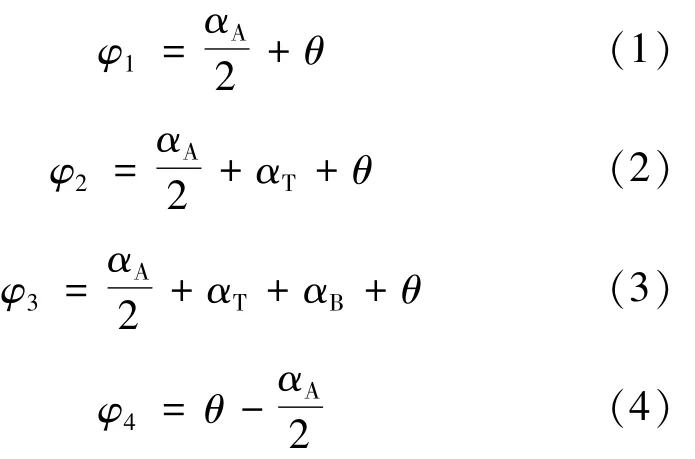
Whereφ1,φ2,φ3andφ4are the boundary angles of the kidney-shapedholes(°),respectively.θis the ro-tation angle of the valve plate relative to the top dead center(°),it is also called as the control angle of the valve plate and the value ofθranges from 0°to 90°,αA、αB、αO、αTare thesucking or discharging angles of port A,B,O and T(°),respectively.And

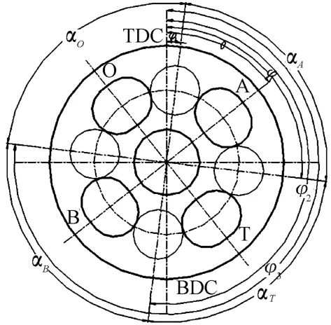
Fig.3 Ang Ie re Iationship between kidney-shaped ho Ies and the rotation ang Ie of the va Ive p Iate
Based on the kinematics analysis of the plunger,the displacement of the four kidney-shaped holes A,B,O and T of the FHT can be obtained(m3/rad).

WhereK=ZrAsinβ,Zis the number of plungers,Ais the cross section area of the column plug hole(m2),ris the distribution circle radius of the connecting rod ball head on the spindle disk(m),βis the angle between the drive shaft and the center line of the cylinder(°),it can be obtained from(1)to(8)as follows.

As can be seen thatVA=-VB,VO=-VT.
2.2 Themathematicalmodels of the FHT torque
It can be seen from the working principle of the FHT,the combination of port A and port B is equivalent to a hydraulic motor,the combination of port O and port T is equivalent to a hydraulic pump,the theoretical output torque of the A-B(port A to port B)is shown as follows[9-10].

WhereΔpABv=pA-pB
The actual output torque of the A-B(port A to port B)is shown as follows.

WhereΔTpABis the friction torque loss caused by pressure,ΔTVABis the friction torque loss caused by the viscosity of themedium,Cmis themechanical friction torque loss coefficient,CVis the viscous friction torque loss coefficient,μis the dynamic viscosity of the working oil,ωis the rotational angular velocity of the hydraulic transformer cylinder.
The theoretical input torque of the O-T(port O to port T)two is shown as follows.

WhereΔpOT=pO-pT.
The actual input torque of the O-T(port O to port T)is shown as follows.

WhereΔTpOTis the friction torque loss caused by pressure,ΔTVOTis the friction torque loss caused by the viscosity of themedium.
2.3 Themathematicalmodel of the FHT pressure transformation ratio
When the FHT works stably at a certain speed,the torque at the four ports of the FHT acts on the cylinder body and the torque is balanced under this circumstance.

The differential pressure(ΔpOT)between port O and port T of the FHT and the differential pressure(ΔpAB)between port A and port B can be obtained from equation(14)and(16),the ratio of differential pressureΔpOTtoΔpABis defined as the pressure transformation ratio of the FHT.

The core variable in equation(18)is the cylinder speed,the relationship between the speed of the cylinder body and the actual flow rate of port B is shown as follows.

IfC1is the laminar flow leakage coefficient of the FHT,C1=3.3×10⁻⁸,then equation of the pressure transformation ratio can be rewritten as another(20)inwhich the output flow rate of port B is a variable.

If mechanical friction torque loss and viscous friction torque loss are not considered,that isCm=0,CV=0 in equation(18),the theoretical pressure transformation ratio of the FHT is obtained.

3 Analysis of factors affecting the p ressure transform ation ratio of the FHT
According to equation(20),the coefficient of the theoretical transformation ratio’sfirst termis less than 1,thismeans that the theoretical transformation ratiodecreases with the increment of mechanical friction loss coefficientCm.That is to say,when the control angle of the valve plate is constant,the pressure transformation ratio decreaseswith the incrementof themechanical friction loss coefficient.The viscous friction loss coefficientCVand the laminar flow leakage coefficientC1of the second term of equation(20)are on the numerator,it shows that the transformation ratio decreases with the increment of viscous friction and laminar leakage.The recycling pressure difference is on the denominator,as the recycling pressure difference increases,the effect of viscous friction and laminar leakage on the transformation ratio is reduced.
The equation of the pressure transformation ratio is complex and inconvenient to use,according to experience[11],the laminar flow leakage coefficientC1=3.3×10⁻⁸,the viscous friction loss coefficientCV=206 000 and the mechanical friction loss coefficientCm=0.076,dynamic viscosity ofworking oilμ=0.03 Pa·s,K=ZrAsinβ,whereZ=7,r=1.26×10⁻⁴m,A=2.659×10⁻⁴m2,β=40°,i.e,K=15 cm3.According to the dimensional relationship,the equation(18)and(20)of the pressure transformation ratio are simplified as follows[11].
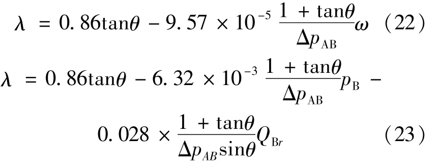
Where the unit ofΔpABis MPa,the unit ofQBris L/min,the unit ofωis r/min.
3.1 The effect of low-pressure port B flow rate on the transformation ratio
In order to ensure the stability of the pressure transformation ratio characteristics,it is essential to study the interfering factors of the transformation ratio,it can be known from equation(18)that one of the important interfering factors is the change in the flow rate of the port B,i.e.the change in the rotational speed of the cylinder,in order to analyze the influence of the rotational speed on the pressure transformation ratio,the partial derivation of(18)with respect to the rotational speed is shown as follows.

According to equation(24),∂λ/∂ω<0,therefore,when the other parameters are unchanged,the increase in the rotational speed of the cylinder can reduce the pressure ratio.
The simulation curves of the relationships between the rotational speed,flow rate,control angle of the valve plate and the pressure transformation ratio of the FHT are shown in Fig.4.The equal pressure transformation ratio simulation curve of the FHTwith the rotational speed of the cylinder and the control angle of the valve plate as variables is shown in Fig.4(a).When the simulation parameters have the values,pA=20 MPa andpB=10 MPa,it can be seen in more detail from the curve in the Fig.4(a)thatwhen the angle of the valve plate is unchanged,the pressure transformation ratio of the FHT will decrease with the increment of the rotational speed of the cylinder,the reason is thatwhen the control angle of the valve plate is constant,the increment of the rotational speed of the cylinder will increase the viscous friction torque loss,resulting in a decrease in the pressure transformation ratio.
Under the same conditions,the equal pressure transformation ratio simulation curve of the FHT with actual flow rate of port B and the control angle of valve plate as variables is shown in Fig.4(b).Comparing Fig.4(a)and 4(b),it is found that the influence trend of the output flow rate on the transformation ratio is basically the same as the influence of the rotational speed on the transformation ratio.The reason is that when the control angle of the valve plate is constant,the output flow rate is close to the linear relationship of cylinder speed.

Fig.4.Simu Iation curve of the FHT pressure transform ation ratio characteristics
The equal flow rate simulation curve of the FHT with the control angle of valve plate and the pressure transformation ratio as variables is shown in Fig.4(c).It can be seen from the curves in the Fig.4(c)that in the case of the same transformation ratio,large flow rate corresponds to the large control angle of the valve plate.The reason is that the increase in flow rate is caused by the increment of the cylinder speed,and the increment of cylinder speed will increase the viscous friction torque loss of the FHT.In the case of different flow rate,to get the same pressure transformation ratio,it is necessary to change the control angle of the valve plate.
3.2 Effectof recycling pressure differenceon the pressure transformation ratio
During the working process of the FHT,the recycling pressure difference(ΔpAB)varies greatly with the working conditions,it is important to analyze its effect on the transformation ratio characteristics.The partial derivation of equation(18)with respect to the recycling pressure difference is shown as follows.

According to the equation(25),∂λ/∂ΔpAB>0,when the other parameters are unchanged,the increment of the recycling pressure difference of the FHT can increase the pressure transformation ratio.As shown in Fig.5.
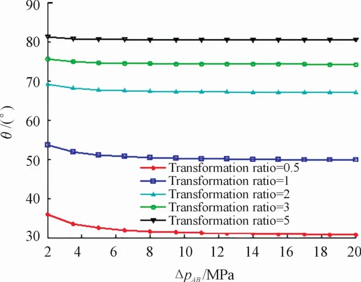
Fig.5 Simu Iation curve of the effect of recyc Iing p ressure difference on the p ressure transform ation ratio
When the transformation ratio is relatively small,the recycling pressure difference has great influence on it,the reason is thatwhen the pressure transformation ratio is small,the first term in equation(18)is small,and the effect of recycling pressure difference in the second term on the transformation ratio is significant relative to the first term.When the recycling pressure difference increases,the influence on the transformation ratio becomes smaller,the reason is that when recycling pressure difference is large,the first term in equation(18)is large,and the recycling pressure difference in the second item is on the denominator,so the influence on the transformation ratio is small relative to the first item.
3.3 Effect of oil viscosity on the pressure transformation ratio
During the operation of the FHT,the oil temperature varies greatly,resulting in great changes in oil viscosity,it is also important to analyze its effect on the pressure transformation ratio characteristics.The partial derivation of equation(18)with respect to the oil viscosity is shown as follows.

According to equation(26),∂λ/∂μ<0,when the other parameters are unchanged,the decrease of the oil viscosity will increase the pressure transformation ratio.Fig.6 shows that the effectof oil viscosity on the pressure transformation ratio,in equation(26),pA=20 MPa,pB=10MPa,ω=1 000 r/min.According to the simulation curve of Fig.6,it can be concluded thatwhen the angle of the valve plate is constant,the decrease of oil viscosity causes the reduction of viscous friction torque,so that the pressure transformation ratio of the FHT is increased.Moreover,the influence ismore obviouswhen the rotation angle of the valve plate is larger.
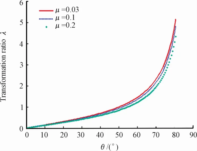
Fig.6 Sim u Iation curve of effect of oiIviscosity on the p ressure transform ation ratio
4 Conclusion
In this work,a kind of four-port hydraulic transformer of inlet and outlet equal flow is proposed and the mathematical model of its transformation ratio is established,the main conclusions about its pressure transformation ratio characteristics are as follows.
(1)This hydraulic transformer has four inlet and outlet ports.Theoretically,the flow rate of port A is the same as port B,the combination of port A and B is equivalent to a hydraulicmotor,and the flow rate of port O is the same as port T,and the combination of port O and T is equivalent to a hydraulic pump.There are four kidney-shaped holeswith the same shape and area on the valve plate,and the pressure transformation ratio can be changed by adjusting the control angle of the valve plate.
(2)When the control angle of the valve plate is constant,the transformation ratio will decrease as the cylinder speed or the oil viscosity increases,in addition,the incrementof the recycling pressure difference will increase the pressure transformation ratio,and when the transformation ratio is relatively small,the recycling pressure difference has great influence on it.The research results not only lay a foundation for the further perfection of the theory of FHT,but also have important reference and guiding significance for its application.
- 机床与液压的其它文章
- Decoupling control of single DOF supporting system ofmagnetic-liquid double suspension bearing
- Influence of the thermal effect on the sealing performance of the hydraulic combined dynam ic seal
- Dynam ic GRNNmodel of hydraulic system fault detection based on the internet of things technology
- Form ing modeling and sensitivity analysis of sandwich composites
- Research of aerodynam ic characteristics of heavy commercial vehicles under crosswind for different urban road layout
- Design ofmulti-parameter ultrasonic measuring instrument for fluid

