基于运动补偿的DMD无掩模光刻拼接误差校正
姜 旭,杨 絮,刘 红,胡 俊,王英志
基于运动补偿的DMD无掩模光刻拼接误差校正
姜 旭*,杨 絮*,刘 红,胡 俊,王英志
长春理工大学电子信息工程学院,吉林 长春 130000
在DMD光刻设备中,由于机械装调产生的机械误差导致曝光图像间产生拼接误差,进而造成曝光图像出现错位、交叠等问题。为了消除DMD在大面积曝光过程中的曝光误差,对误差校正方法进行研究。首先,利用显微镜对曝光后的基板进行测量得到曝光误差。然后,在曝光误差的基础上建立误差模型。最后,根据误差模型提出了基于运动补偿的DMD光刻系统误差校正的方法,该方法有别于目前已有的误差校正方法。实验结果表明,在微米级图像曝光过程中,曝光误差减少了80%以上,DMD曝光中心偏移距离由175 μm减少为21 μm。有效提高曝光图像的拼接精度,满足对大面积曝光图像的高质量、高精度等要求。
DMD光刻;DMD大面积曝光;运动补偿;倾角误差
1 引 言
数字光刻技术是PCB制板的核心技术,随着布线密度增加、蚀刻线宽减小,高精度PCB板对光刻技术和光刻系统提出了更高的要求,所以提升数字光刻系统的精确度具有一定意义[1-3]。
数字微镜器件(Digital micromirror device,DMD)为数字光刻技术中的关键器件,本文使用的DMD单元像素尺寸为13.68mm´13.68mm,并且具有填充比高、响应速度快和对比度高等优点,所以基于DMD的无掩模光刻技术可以曝光出微米级甚至纳米级的图案[4-6]。但在电路板大面积曝光过程中,由于光刻机本身存在着机械误差,尤其是倾角误差,导致大面积曝光的PCB存在图像错位问题[7]。所以减小倾角误差的影响将有效提高曝光精度。
根据目前可查文献,倾角误差校正方法还鲜有研究。减小倾角误差通常采用打表工艺,即使用千分表调整曝光平台和DMD的位置关系,但使用千分表仅可以对DMD的位置进行粗调,调整精度受限于千分表精度和操作人员的操作精度,调整微米级的误差难度较大,因此大面积曝光后的效果并不好;2017年,熊峥提出了图像预处理的方法补偿误差[8],即在曝光前对输入至DMD的图像采用反向位移的方法进行预处理。该方法在曝光一次之后测出误差与理想误差的距离,再根据误差距离,向误差偏移的相反方向调整原始图像,使调整距离等于误差距离,从而完成对偏移图像的校正。该方法在曝光之前需要对每一幅图像进行预处理,在大面积曝光时,预处理的工作量会大大增加,因此该方法存在曝光效率低的问题。
针对以上方法存在的问题,本文从全新的角度提出一种利用运动补偿来校正倾角误差的方法,无需对曝光图像进行处理,可以节约图像预处理的时间,提高曝光精确度和曝光效率。
2 数字光刻系统
数字光刻技术,即基于空间光调制器的光刻技术,是由传统的光刻技术衍生而来,其曝光原理与传统的投影光刻技术较为相似。将所需曝光的图案逐幅输入空间光调制器中,空间光调制器代替传统的光学掩模,再结合投影曝光系统,把最终图案转移到基板上完成曝光[9]。
根据DMD数字光刻技术构建出一套完整的DMD数字光刻系统,图1是数字光刻系统的结构组成,首先由激光器发出功率为3 W、波长为405 nm的曝光光束,光束穿过透镜组,其中包括准直透镜和匀光管等,目的是得到均匀、尺寸合适的矩形光斑。光斑在反射镜反射后投影在DMD上,DMD控制微镜偏转得到曝光图像。为了将曝光图像缩小并在曝光平面上成像,通常在曝光基板和DMD间加入会聚透镜。经过会聚透镜后,完成图像在基板上曝光。在完成一次曝光后,平台运动一定距离,DMD所显示的图像刷新一次,再次进行曝光,重复以上步骤即可完成大面积曝光。
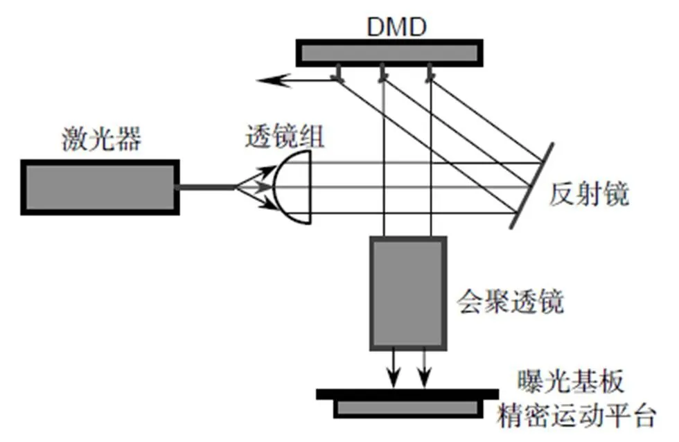
图1 数字光刻系统示意图
为了将曝光图形缩小并在曝光平面上成像,通常在DMD曝光系统中需要一级或者多级微缩[10]。利用会聚透镜可以实现图形微缩,其缩微倍率决定每个像素尺寸和DMD上图形的成像。本文使用的曝光器件是基于DLP架构的DMD,其每个像素单元的尺寸为13.68mm´13.68mm。因此,在不考虑光学像差和衍射等条件的情况下,像方分辨率为

其中:表示会聚透镜的缩放倍率,表示缩放前每个像素单元尺寸,*表示缩放后每个像素单元的尺寸。
3 倾角误差校正方法
3.1 数学模型
在光刻系统的装调过程中,难以保证DMD的行方向与平台的扫描方向装调一致,二者存在一定的夹角,即倾角误差,这种误差使图像在大面积曝光时产生位置错动,造成曝光图像间出现错位问题,严重影响图像曝光效果,需要进行修正。
图2(a)为不平行性误差示意图。以运动平台扫描方向建立全局坐标,以DMD像素中心建立局部坐标系¢¢¢,方向为平台扫描方向,DMD与平台扫描方向存在夹角,为一个DMD像素单元的尺寸。
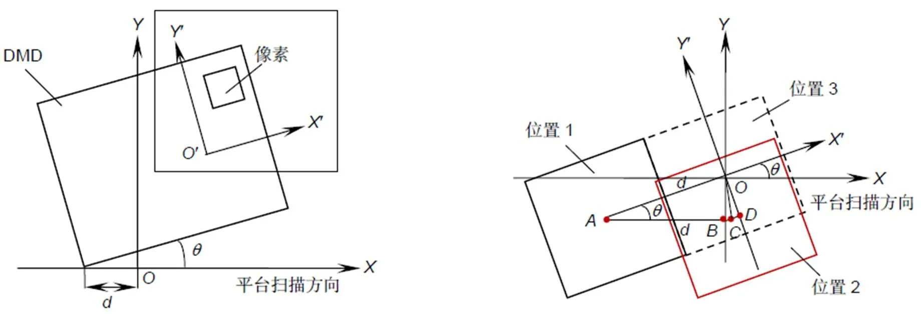
图2 (a) 不平行性误差的示意图;(b) 曝光过程中倾角误差的示意图
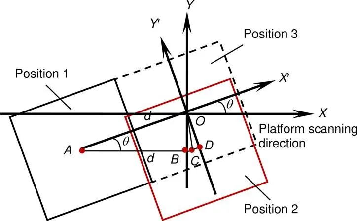
图2(a)是系统在曝光之前的示意图,在曝光过程中,平台每次运动距离后,DMD曝光一次。将图2(a)方框中内容放大,平台移动距离,得到图2(b)曝光过程中的倾角误差示意图。图2(b)中实线方格表示DMD的某像素位置,该像素曝光后,平台将移动距离再曝光一次。理想情况下该像素应该从位置1移动到位置3进行曝光,但因倾角误差的影响,实际测试中DMD沿平台扫描方向,即轴正方向移动距离,则该像素被移动到位置2,导致出现曝光图像错位的问题。
图2(b)中点是位置1的中心,点是位置3的中心,也就是点移动后的理想位置。点是位置2的中心,即点移动后的实际位置,、两点分别是点在平台坐标系和DMD坐标系¢¢¢上纵轴的投影,由图2(b)可以清晰看出每次移动DMD,像素中心都会沿的方向偏移。偏移距离为

在假设已知误差夹角的情况下,根据图2(b)像素间的边角关系,通过以下公式进行计算:


其中:和表示在平台坐标系上当前曝光位置到下一次曝光理想位置需移动横轴和纵轴的距离,*表示单个像素的大小。
得到和后,在平台每次运动时,控制横轴移动,纵轴移动,这样可以将像素从位置1移动到位置3,有效避免因倾角误差造成的问题,提高曝光精确度。
3.2 运动补偿的校正方法
根据上述DMD光刻技术原理及倾角误差产生原理,本文针对曝光图像错位的问题,提出基于运动补偿的倾角误差校正方法,并进行实验验证。图3为实验步骤示意图。
由于每个像素单元的尺寸较小,会增加测量难度,所以本实验采用步进式曝光方式,即每次移动一个DMD的尺寸再曝光,可以提高测量精度[11]。
首次曝光实验为了得到存在倾角误差的图像,在DMD上使用井字型图案进行曝光可以在一次实验中同时得到方向和方向上的误差夹角。图4以方向为例测量误差夹角,图形中线段是DMD的行方向,曝光两次图形后同一点的连线是平台的扫描方向。这两条线的夹角是误差夹角,如图4中两条红线的夹角所示。
首先根据像方分辨率的公式计算每个像素单元的尺寸:
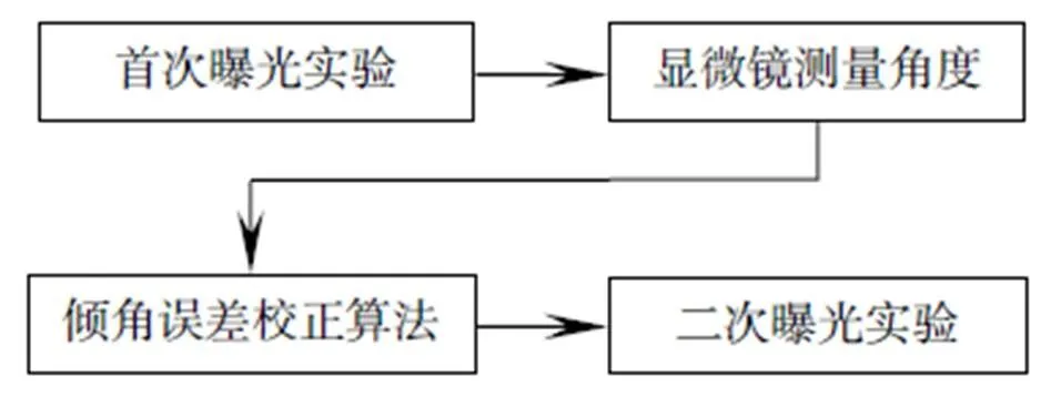
图3 曝光实验步骤示意图
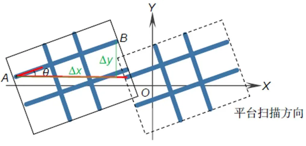
图4 角度测量示意图

DMD的分辨率是1024´768,在得到误差夹角后可以利用倾角误差校正方法求出D和D的数值:


得到误差校正参数后,另取一块基板,对图像进行第二次曝光实验,除误差校正参数外,其余实验参数与首次曝光实验参数一致,可达到误差校正的目的。
4 实验结果
本次实验使用分辨率为1024´768的DMD、精度为3mm的大理石平台以及型号为BL-SC1600的显微镜。实验过程中,DMD表面光束功率为200 mW,曝光时间为7 s,显影时间为5 min。
第一次曝光实验的曝光图案如图5所示,对该图案进行3´3的大面积曝光,曝光结果如图6所示,曝光图形的整体线路较清晰,但图案连接处的误差较明显,需要对误差夹角做进一步测量并校正。使用BL-SC1600显微镜放大误差位置,并在软件上手动标定误差位置,可以测出误差夹角。图7为测量结果。
实验使用缩放倍数为2.2的会聚透镜,根据像方分辨率的公式进行计算:

在得到误差夹角后,可以利用倾角误差校正方法求出D和D的数值:


其中:DMD投影在基板上的每个像素大小为6.218mm,所以平台每次运动横轴移动长度为6.364 mm,纵轴移动长度为0.148 mm,即可以完成对倾角误差的校正。


得到误差校正参数后,另取一块基板,对图像进行第二次曝光实验,实验结果如图8。对首次曝光实验和二次曝光实验结果进行对比,测量位置为图9中标号的位置,其中③~⑧位置测量轴方向的误差夹角,其余位置测量轴方向的误差夹角,测量结果如表1所示。首次曝光误差倾角均值是1.860°、方差是0.045,经过倾角误差校正后,误差均值为0.235°,方差为0.007,平均缩减率是89%。首次曝光的中心偏移距离均值为0.175 mm,经过校正后中心偏移距离均值为0.021 mm。对校正后的误差进行分析,该误差主要与光刻胶性能、曝光时间、显影时间等多方面工艺因素有关,为进一步提高精度可以提高工艺水平。
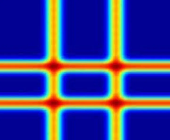
图5 曝光图案示意图
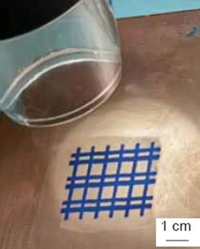
图6 大面积曝光结果
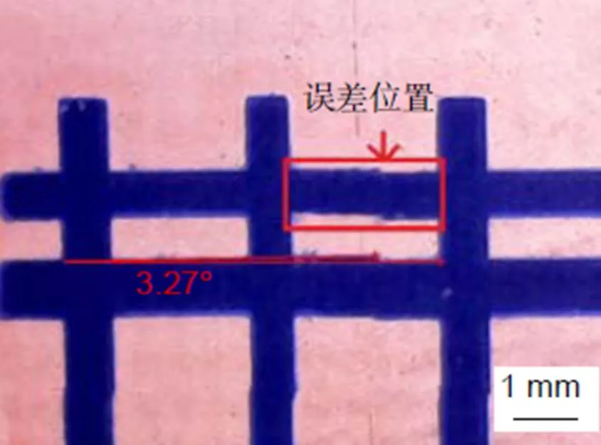
图7 误差测量结果
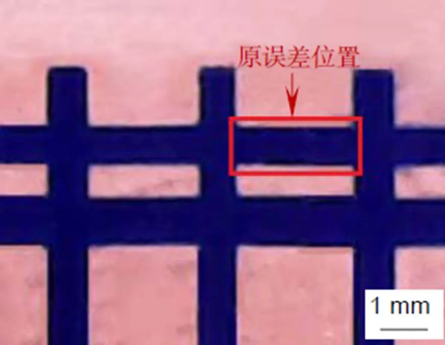
图8 校正后曝光实验结果
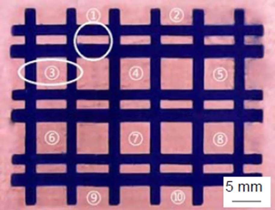
图9 校正后大面积曝光结果
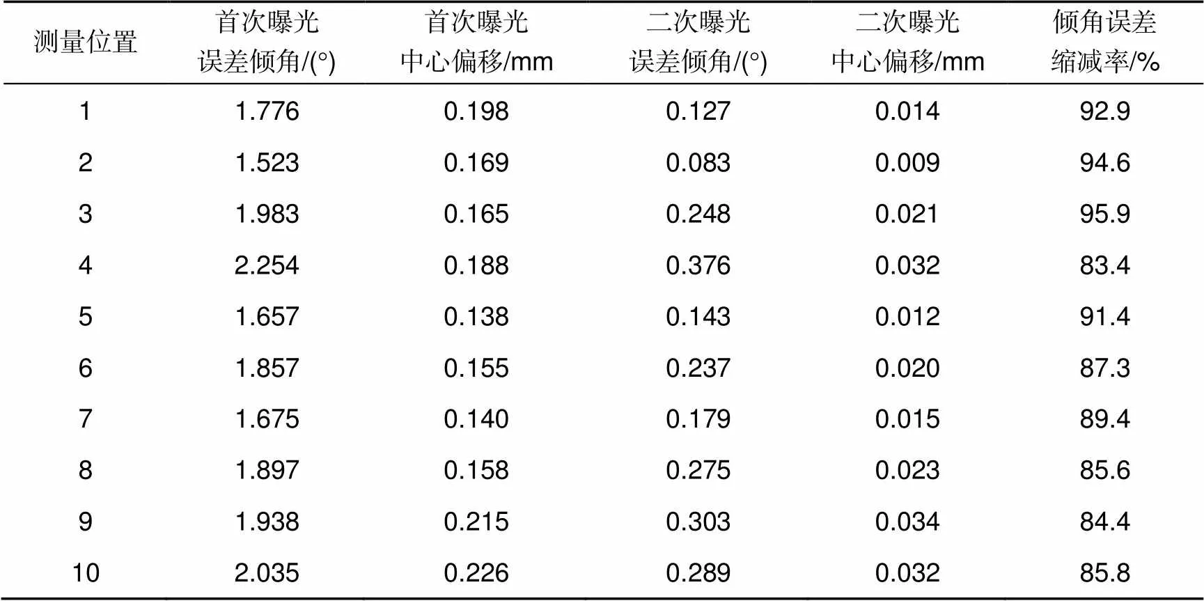
表1 多次曝光校正前后对比
5 结 论
本文提出了基于运动补偿的DMD光刻系统倾角误差校正的方法,论证了倾角误差校正方法的可行性,并通过实际曝光实验进行了验证,试验表明:倾角误差在进行校正之后总体减少了89%,该方法相比于千分表校正的方法提高了曝光精确度,相比于图像预处理方法改善了实验复杂度和实验效率。
[1] Zhong K J, Gao Y Q, Li F,. Fabrication of continuous relief micro-optic elements using real-time maskless lithography technique based on DMD[J]., 2014, 56: 367–371.
[2] Liu W H. The status and future of lithography and it's application[J]., 2006, 36(3): 36–42.
刘文辉. 光刻技术及其应用的状况和未来发展[J]. 电子工业专用设备, 2006, 36(3): 36–42.
[3] 姚汉民, 胡松, 邢廷文. 光学投影曝光微纳加工技术[M]. 北京: 北京工业大学出版社, 2006: 9–13.
[4] Feather G A, Monk D W. The digital micromirror device for projection display[C]//, San Francisco, 1995, 27: 43–51.
[5] Jiang W B, Hu S. Study on maskless lithography technology[J]., 2008(4): 1–3, 64.
蒋文波, 胡松. 无掩模光刻技术研究[J]. 微细加工技术, 2008(4): 1–3, 64.
[6] Sampsell J B. An overview of the digital micromirror device (DMD) and its application to projection displays[J]., 1993: 24.
[7] Zou P F. Research and design of maskless digital lithography based on DMD[D]. Nanjing: Nanjing University, 2017.
邹朋飞. 基于DMD无掩模数字光刻机的研究与设计[D]. 南京: 南京大学, 2017.
[8] Xiong Z. Research on DMD-based digital photolithography[D]. Changchun: University of Chinese Academy of Sciences, 2016.
熊峥. 基于DMD的数字光刻技术研究[D]. 长春: 中国科学院大学, 2016.
[9] Chen R H. Research on optimization scheme of generation quality of patterns in scanning lithography system based on DMD[D]. Changchun: Northeast Normal University, 2018.
陈荣环. 基于DMD的扫描光刻系统图案生成质量优化方案的研究[D]. 长春: 东北师范大学, 2018.
[10] Wu H. Development of DMD-based micro-lithography system and adapted to photo-patterning in liquid crystal alignments[D]. Nanjing: Nanjing University, 2012.
吴皓. DMD投影光刻系统的开发设计及其在光刻、液晶光控取向方面的应用[D]. 南京: 南京大学, 2012.
[11] Wu Y. Research on maskless lithography technology and exposure method[D]. Xi’an: Xidian University, 2017.
武洋. 无掩模光刻技术及其曝光方案研究[D]. 西安: 西安电子科技大学, 2017.
[12] Wang Y F. Study of digital maskless lithography technology and large area exposure method[D]. Xi’an: Xidian University, 2015.
王亚飞. 数字无掩膜光刻技术及其大面积曝光方案研究[D]. 西安: 西安电子科技大学, 2015.
DMD maskless lithography stitching error correction based on motion compensation
Jiang Xu*, Yang Xu*, Liu Hong, Hu Jun, Wang Yingzhi
Electronic Information Engineering, Changchun University of Science and Technology, Jilin, Changchun 130000, China
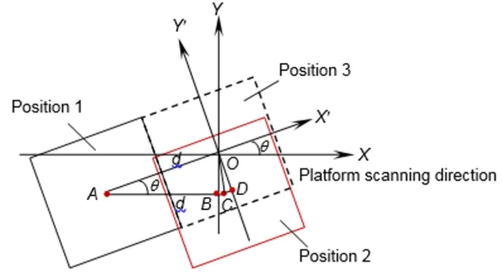
Schematic diagram of the inclination error during exposure
Overview:Digital lithography is the core technology of PCB board. As the wiring density increases and the etch line width decreases, high-precision PCB boards place higher demands on lithography systems. Digital micromirror device (DMD) is a key component in digital lithography. The DMD unit used in this paper has a pixel size of 13.68 μm×13.68 μm and has the advantages of high filling ratio, fast response and high contrast. Mask lithography can expose micron or even nanoscale patterns. In the large-area exposure process, since the size of the PCB board is much larger than the size of the DMD, in order to obtain a high-precision PCB board, it is necessary to improve the stitching precision of the exposed image. But for the DMD lithography equipment, due to the exposed images joint errors which caused by mechanical loading errors, problems such as misalignment and overlap of the exposed images may arise. After the pixel is exposed, the platform will re-exposure the moving distance. Ideally, the pixel should be moved from position 1 to position 3 for exposure due to tilt error. The effect, in the actual test, the DMD moves along the platform scanning direction, that is, the-axis positive direction moves a certain distance, then the pixel is moved to the position 2, resulting in the problem of misalignment of the exposed image. In order to eliminate the exposure error of DMD during large-area exposure, the error correction method was studied. Firstly, the exposure error was got by measuring the exposed substrate with a microscope. Then, an error model was established based on the known exposure error. Finally, an error correction based on motion compensation for DMD lithography system was proposed based on the error model. After measuring the tilt error, the method calculates the-axis offset of the image by using the triangular relationship, and then realizes the error compensation through the platform motion. The experimental results show that during the micron image exposure process, the exposure error is reduced by more than 80%, and the DMD exposure center offset distance is reduced from 175 μm to 21 μm. The stitching accuracy of the exposed image is improved effectively, which meets the requirements for high quality and high precision of large-area exposure images.
Citation: Jiang X, Yang X, Liu H,DMD maskless lithography stitching error correction based on motion compensation[J]., 2020, 47(6): 190387
DMD maskless lithography stitching error correction based on motion compensation
Jiang Xu*, Yang Xu*, Liu Hong, Hu Jun, Wang Yingzhi
Electronic Information Engineering, Changchun University of Science and Technology, Jilin, Changchun 130000, China
For the digital micromirror device (DMD) lithography equipment, due to the exposed images joint errors which caused by mechanical loading errors, problems such as misalignment and overlap of the exposed images may arise. In order to eliminate the exposure error of DMD during large-area exposure, the error correction method was studied. Firstly, the exposure error was got by measuring the exposed substrate with a microscope. Then, an error model was established based on the known exposure error. Finally, an error correction based on motion compensation for DMD lithography system was proposed based on the error model. This method is different from the existing error correction method. The experimental results show that during the micron image exposure process, the exposure error is reduced by more than 80%, and the DMD exposure center offset distance is reduced from 175 μm to 21 μm. The stitching accuracy of the exposed image is improved effectively, which meets the requirements for high quality and high precision of large-area exposure images.
DMD lithography; DMD large area exposure; motion compensation; inclination error
TN29
A
10.12086/oee.2020.190387
: Jiang X, Yang X, Liu H,. DMD maskless lithography stitching error correction based on motion compensation[J]., 2020,47(6): 190387
姜旭,杨絮,刘红,等. 基于运动补偿的DMD无掩模光刻拼接误差校正[J]. 光电工程,2020,47(6): 190387
Supported by Jilin Province Science and Technology Development Plan Project (20170204053GX)
* E-mail: 273944219@qq.com; Ibaomi@cust.edu.cn
2019-07-05;
2019-08-15
吉林省科技发展计划项目(20170204053GX)
姜旭(1996-),男,硕士研究生,主要从事激光印刷技术的研究。E-mail:273944219@qq.com
杨絮(1980-),女,博士,副教授,主要从事数字图像处理方面的研究。E-mail:Ibaomi@cust.edu.cn

