Progress on CASEarth Satellite Development*
2020-04-16 14:16:00GUOHuadongCHENHongyuCHENLiangfuFUBihong
空间科学学报 2020年5期
GUO Huadong CHEN Hongyu CHEN Liangfu,3 FU Bihong
Progress on CASEarth Satellite Development*
GUO Huadong1CHEN Hongyu2CHEN Liangfu1,3FU Bihong2
1 (100101) 2 (201204) 3 (100049)
CASEarth satellite is the first space Earth science satellite produced by the Chinese Academy of Sciences. The satellite has three payloads: high-definition Thermal Infrared Spectrometer (TIS), high- definition Glimmer Imager for Urbanization (GIU), and high-definition Multispectral Imager for Inshore (MII). These payloads are used to explore the urbanization level and residential layout, the coastal ecosystem, and new methods and approaches of environmental detection during night-time and even under conditions of polar aurora and provide scientific evidence for the refined depiction of human traces. The CASEarth satellite can provide space observation data for A Project on Big Earth Data Science Engineering as well as scientific and application studies inside and outside China.
CASEarth satellite, Human traces, Thermal infrared spectrometer, High-definition glimmer imager for urbanization, Multispectral imager for inshore
1 Introduction
As an organic component of Project on Big Earth Data Science Engineering dominated by the Chinese Academy of Sciences, the CASEarth satellite, also known as the Guangmu Earth science satellite, was established in July 2018. The satellite is the first space Earth science satellite in China developed by Chinese Academy of Sciences. It is intended for a refined depiction of human traces based on the requirements of residential layout, energy consumption, and coastal environment. Apart from three optical payloads in this satellite, a ground support system and a scientific application system are constructed. This satellite aims to provide spatial observations and support relevant scientific explorations domestically and internationally.
2 Scientific Objectives
The philosophy of the CASEarth satellite design is owning what others do not have and owning what better than others. The satellite is used to explore the urbanization level and residential layout, coastal ecosystem and new methods and approaches of environmental detection during night-time and even under conditions of polar aurora and provide scientific evidence for the refined depiction of human traces. The scientific objectives to be achieved through the CASEarth satellite are as followed.
(1) Comprehensively evaluate the development levels and social and economic development status of the cities involved in the Belt and Road Initiative. Use the thermal infrared and glimmer sensors to provide continuous and stable wide-range thermal infrared and glimmer remote sensing observations, then to quantify the magnitude of thermal radiation and light intensity. After that, the modelling relationship between urban spatial distribution, urban energy consumption, urban light data and thermal radiation data will be obtained. Finally, analyze and disclose social and economic patterns, such as social and economic status, human activity status and energy consumption, and therefore realize dynamic monitoring and analysis of urban development levels and social and economic development status for the economic and energy corridors of the Belt and Road Initiative by combining urban spatial layouts and other social and economic statistics.
(2) Evaluate the regional differences and spatial layouts of the economic development in China. Based on infrared, glimmer, and multispectral comprehensive remote sensing data, detect urban and rural space human activity status and study the development differences, urbanization levels, and city and town distribution on both sides of the Hu Line. Explore the characteristics of urban functional areas, differences between old and new urban areas in a city, and characteristics of urban thermal environment and residential layout space distribution.
(3) Study the ecological environment quality of the coastal environment and the coastal zone. Use the three loads configured for the satellite to detect colored dissolved organic matter, chlorophyll and other water pollutants, locate the sources of coastal heat emission and pollutant discharge, detect port function areas, scales, and activity levels, and comprehensively evaluate the impact degrees of human activities along the coastal zone.
Based on the above-mentioned items, the CAS- Earth satellite will blaze the trail in the detection of nighttime urban particulate pollution and study the mechanism, using quantitative moonlight observation in snow-covered polar regions during polar nights to fill a gap in moonlight remote sensing in such regions.
3 Scientific Payloads
For a refined depiction of human trace information, such as residential layouts, energy consumption, and coastal ecology, the CASEarth satellite equipped with three payloads: high-definition Thermal Infrared Spectrometer (TIS), high-definition Glimmer Imager for Urbanization (GIU), and high-definition Multispectral Imager for Inshore (MII). The high-definition GIU and the high-definition MII share a common optical path and are integrated into one device called Glimmer and Multispectral Imager (GMI). The TIS is used for global thermal radiation detection, the GIU for observing lamplight on the Earth surface during night, and the MII mainly for coastal zone and specially for water environment observation.
3.1 TIS
Based on traditional surface temperature infrared split-window method (within the bands of 10.3~11.3 μm and 11.5~12.5 μm), a new band of 8~10.5 μmis added to TIS. The new configuration ensures higher surface temperature retrieval accuracy. The specific indexes are as follows.
(1) Imaging range width: ≥300 km at 505 km.
(2) Pixel resolution: 30 m at 505 km (sub-satellite point).
(3) Detection spectra.
Waveband B1: 8~10.5 μm.
Waveband B2: 10.3~11.3 μm.
Waveband B3: 11.5~12.5 μm.
(4) NETD. Waveband B1: ≤0.2 K at 300 K. Waveband B2: ≤0.2 K at 300 K. Waveband B3: ≤ 0.2 K at 300 K.
(5) Dynamic range: 220~340 K.
(6) Digitalizing bit: ≥12 bit.
(7) Static/Dynamic MTF: ≥0.17/0.10.
(8) Radiometric calibration uncertainty: absolute calibration better than 1 K at 300 K, relative calibration better than 5%.
3.2 GIU
The GIU is mainly used to obtain wide-range and high-resolution panchromatic and RGB glimmer data at night in the orbit, perform high-precision radiation calibration, provide nighttime glimmer images for big data scientific engineering of the Earth and evaluate residential layouts and urbanization development levels through lamplight distribution and lamplight quality. To comprehensively collect and detect lamplight data of different types (incandescent lamp, neon light, high voltage mercury lamp, xenon lamp, LED lamp, and others), the wide waveband of 430~900 nm is adopted for design, and panchromatic band data are collected to improve the SNR. Considering the requirements of lamplight type differentiation and nighttime particle detection in cities, the wavebands are sub-divided into three bands of RGB.
(1) Spectrum range. Panchromatic: 430~900 nm. B: 430~520 nm. G: 520~615 nm. R: 615~900 nm.
(2) Panchromatic spatial resolution: 10 m at 505 km.
(3) RGB spectral spatial resolution: 40 m at 505 km.
(4) Imaging range width: ≥300 km at 505 km.
(5) SNR. Panchromatic: City’s main road lamplight (1.0×10⁻²W·m–2·sr–1)≥50; city and town residential area (1.6×10⁻³W·m–2·sr–1)≥10; polar moonlight ≥10. RGB: City’s main road lamplight (1.0× 10⁻²W·m–2·sr–1)≥50; city and town residential area (1.6×10⁻³W·m–2·sr–1)≥10.
(6) Digitalizing bit: ≥12 bit.
(7) Static/Dynamic MTF: ≥0.23/0.10.
(8) Camera radiometric calibration uncertainty (RMS, the full field of view). Relative calibration: better than 2%. Absolute calibration: better than 5%.
3.3 MII
Retrieval study results of existing water quality parameters and simulation and analysis of water quality measurement spectra for the Yangtze River mouth, the Tai Lake and other locations show that, for suspended sediment detection, the traditional red light wave band (660±30 nm) is sensitive to a low sediment content, while the red edge wave band (785±20 nm) is more sensitive to a high sediment content; the deep blue wave band (440±20 nm) and the blue waveband (490±30 nm) are relatively sensitive for chlorophyll A detection in water, and deep blue wave band (400±20 nm) shows better performance in CDOM detection. To differentiating mangroves and extracting on-land vegetation coverage, the green light wave band (560±40 nm) and the near- infrared waveband (852.5±47.5 nm) must both be involved. Therefore, the indices of the CASEarth MII are designed as follows.
(1) Spectrum settings:
B1 (deep blue 1) 380~420 nm,
B2 (deep blue 2) 420~460 nm,
B3 (blue) 460~520 nm,
B4 (green) 520~600 nm,
B5 (red) 630~690 nm,
B6 (red edge) 765~805 nm,
B7 (near-infrared) 805~900 nm.
(2) Each spectrum’s pixel resolution: 10 m at 505 km.
(3) Imaging range width: ≥300 km at 505 km.
(4) SNR: B1>130, B2~B7>150.
(5) Code rate: not more than 2.4 Gbit·s–1(uncompressed, total).
(6) Static/Dynamic MTF: ≥0.23/0.10.
(7) Camera radiation calibration uncertainty (RMS, the full field of view). Relative calibration: better than 2%. Absolute calibration: better than 5%.
4 Guangmu Earth Science Satellite Mission
4.1 Satellite System
4.1.1 Satellite Orbit
It is desirable to use the CASEarth GIU to observe the cities and towns during the period (19:00 LT– 22:00 LT) at night when there are relatively intense activities. It is required that the observation area's solar elevation angle be ≥30° to ensure enough SNR when the MII is used for observation. Based on these two requirements and considering the need to use ground reception stations through staggering to avoid competing with other in-orbit remote sensing satellites for arc resources, the Sun-synchronous orbit with the descending node of 09:30 LT is selected. During orbit ascending, the sub-satellite point is at night (18:00 LT–22:00 LT) and glimmer observation is performed; during orbit descending, the sub-satellite point is at daytime and MII observation is performed (09:00 LT–10:00 LT). The TIS can work at any point in the orbit. The specific orbit parameters are as follows.
(1) Orbit type: Sun-synchronous orbit.
(2) Standard orbit height: 505 km.
(3) Inclination angle: 97.5° (+0.1° compared with SSO small bias to ensure orbit injection descending node).
(4) Descending node: 09:30 LT.
(5) Height variation range: 500~510 km.
On the orbit of 500 km to 510 km, the time required for the satellite payload with a 300 km range width to cover the entire Earth is about 11 to 15 days.
4.1.2 Observation Mode and Pointing Direction
The satellite task includes three observation modes: general survey observation, expansion observation, and emergency observation. There are six calibration modes for three types of payload.
4.1.2.1 General Survey Observation Mode
It is the most common in-orbit observation mode. The observation is implemented through on-satellite autonomous task planning by default. The satellite attitude is Earth center pointing and the drift angle is corrected. The ground observation areas (city, country, region, and others) are divided into not more than 100 polygonal areas. Based on the orbit extrapolation sub-satellite position and solar elevation angle and the autonomously determined power-on type on the satellite, autonomous preparation of payload and DDT, power-on, imaging, data storage, and power-off is performed.
For key observation areas (top priority areas: Beijing-Tianjin-Hebei, Yangtze River Delta, Zhujiang River Delta, the biggest three lakes in China and the Silk Road on Sea), observation performs at each orbit if possible. Based on coverage simulation, the observation longest time for each orbit is summarized in Table 1.
After the observation of the key areas is completed, observation performs for areas with level-2 (inland cities of The Belt and Road, cities with a population of over one million and the capital; Silk Road on Land) and level-3 (the entire world with the focus on global metropolises) priority to cover key areas of The Belt and Road and the areas across the globe.
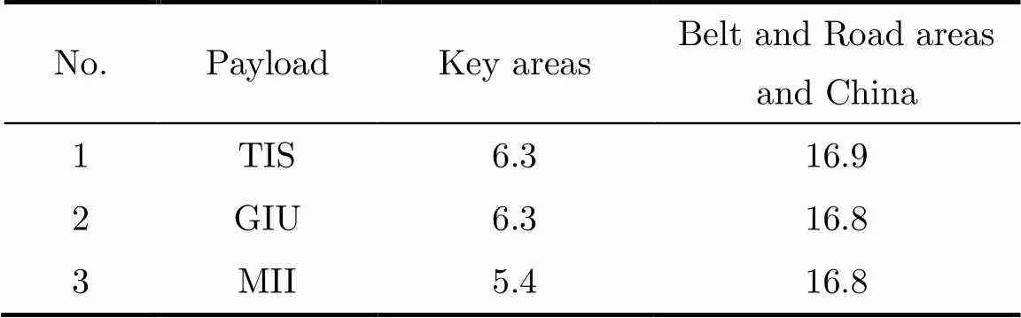
Table 1 Maximum observation time summary per orbit (Unit min)
4.1.2.2 Expansion Observation Mode
Arctic and Antarctic observation is an expansion task for the CASEarth satellite. When the satellite flies over the Arctic and the Antarctic, it is planned that it will use as little time as possible with a resolution as high as possible and with as fewer times of attitude maneuvers to cover the entire regions through infrared, glimmer and multispectral observation using satellite side swing and payload imaging parameter settings.
With a satellite orbit inclination of 97.5°, the sub-satellite point cannot cover the entire Arctic and Antarctic regions (66.5°N/S to 90°N/S) and therefore the observation of these regions is made through satellite side swings. The satellite needs to make a side swing of 40° and therefore to observe the poles to reduce big-angle side swing time and increase as much resolution as possible. Two angles are adopted for observation of the Arctic and Antarctic regions. With the side swing of 40°, it takes 0.5 days to cover the areas from 84.5°N/S to the North Pole or the South Pole. For details, see Figure 1. With the side swing of 25°, it takes 2.5 days to cover the areas from 66.5°N/S to 84.5°N/S. Considering coverage time, ground resolution, data volume and TIS thermal constrains, it takes 5 days for polar night coverage and 12 days for polar day coverage without side way.
Five minutes before polar region range entry for each orbit, the satellite performs side swing maneuver to enter polar region observation mode and resume its original position and enter standby mode after leaving the corresponding polar region.
The observation sub-modes include Arctic polar night observation, Arctic polar day observation, Antarctic polar night observation, and Antarctic polar day observation. Polar day observation will be carried out in the polar summer. The Sun elevation angle is the main factor that affects irradiance in the polar region. The changes of the Sun elevation angle in the polar regions of different latitude with time are shown in Figure 2.
Polar night observation is based on ice and snow detection experiments under the moonlight during winter nights in the polar regions. The Moon elevation angle is the main factor that affects irradiance in the polar region. The changes of the Moon elevation angle in the polar regions of the different latitude with time are shown in Figure 3.
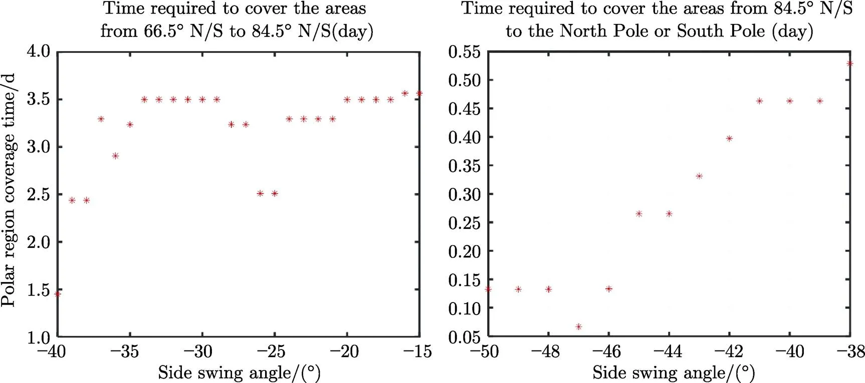
Fig. 1 Relationship between side swing angles and polar region coverage time
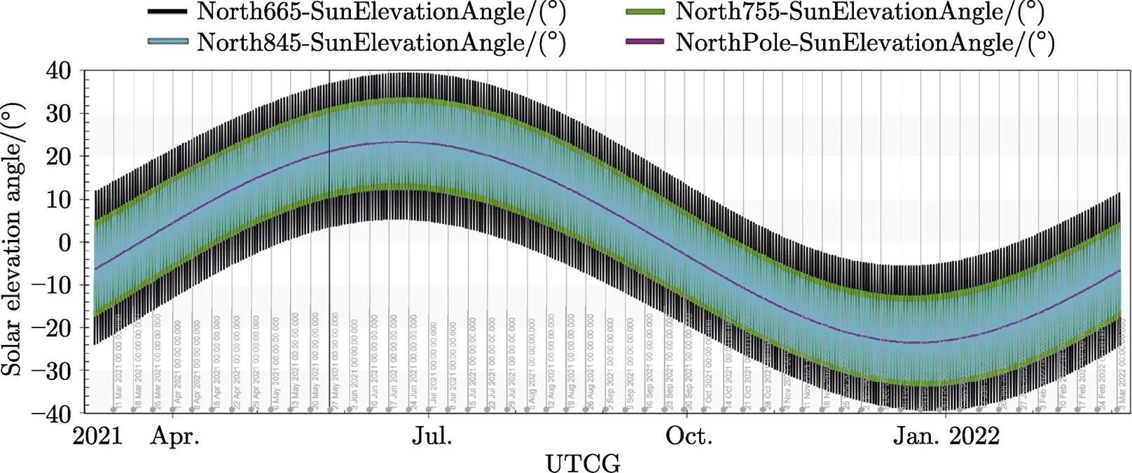
Fig. 2 Relationship between Solar elevation angle and the different latitude

Fig. 3 Relationship between Moon elevation angle and the different latitude
The ideal condition for polar region observation is when the Moon elevation angle is over 24°. The GIU adopts image motion compensation to increase exposure time and improve the glimmer observation capability.
4.1.2.3 Emergency Observation Mode
The CASEarth satellite is flexible and mobile and can track and shoot photos of specific targets in emergencies in a directional manner. It can adjust its attitude through simultaneous rolling and yawing to perform tracking and observation for targets more than 300 km away from the sub-satellite point.
4.1.2.4 Payload Calibration Mode
(Ⅰ) TIS black body + cold sky calibration
The TIS combines the full-aperture black body and cold sky background to perform radiation calibration. There are two calibration modes: black body calibration and cold sky calibration. The mode switch is realized through the inner scanning mirror of the payload. The optical path of the optical system is shown in the following Figure 4.
Satellite pointing and calibration time sequences are shown in Figure 5.
(Ⅱ) GMI Internal Calibration through LED
The LED light source is the standard calibration light source for in-orbit internal calibration. On its basis, the quantitative relationship between the camera’s spectral radiation input and image gray value output. Radiation transmission model parameters of different spectrum channels are calculated regularly in an in-orbit manner to monitor sensor variation and stability and verify and correct the sensor radiation response coefficient.
There are seven sets of LEDs inside each camera, with each set providing main and standby calibration data for adjacent two sensors, as shown in Figure 6. The main data are used for relative radiation correction and the alternate data are used for analyzing light source changes.
In-orbit internal calibration through LEDs is performed for the cameras with the satellite pointing towards the Earth from the 29th day of a month to the 1st day of the next month every month on the lunar calendar during cloudless nights when the satellite pass through a deep-sea area.

Fig. 4 Optical path of TIS optical system

Fig.5 Calibration process diagram of the TIS

Fig. 6 Diagram of light spots on the LED focal plane
(Ⅲ) GMI Calibration against the Moon
Since the attenuation of calibration light sources cannot be measured for the internal calibration method, outside-satellite calibration against the Moon is performed in addition to in-satellite LED calibration. The detector performs push-broom scanning for the entire Moon disk for each spectrum during Moon imaging. The detector push-broom direction is similar to that of the push-broom for the Earth, as shown in Figure 7.
The calibration needs to be performed in two orbits. In each orbit, rectangular scanning is performed for eight detectors of a camera in turn, as shown in Figure 8.
4.1.3 Payload Solution
4.1.3.1 TIS
The TIS adopts a one-dimension whisk-broom system for wide-range thermal infrared observation and channels the collected optical information into the transmission-type low-temperature optical system in the payload and concentrates it on the long-wave focusing plane assembly. The detector then receives the optical information and transforms it into electrical signals through photoelectric conversion. The scanning mode is shown in Figure 9. During the scanning process, forward scanning with a range of 300 km is performed and images are generated. Images are not generated in reverse scanning. Both scanning processes are performed at an even speed.
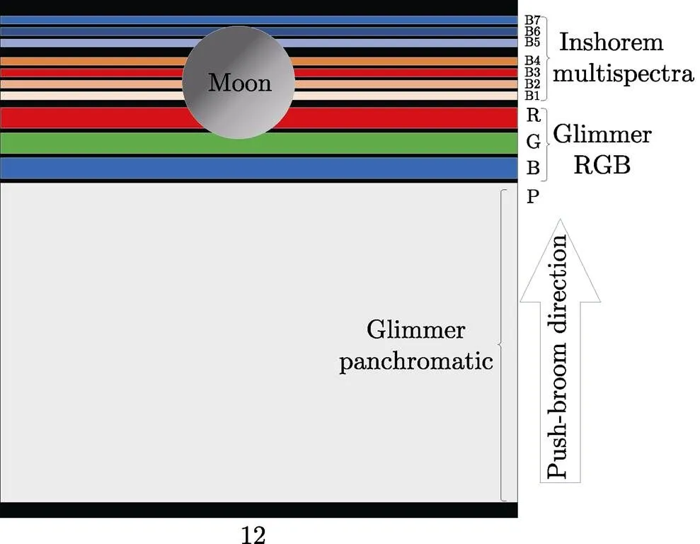
Fig. 7 Diagram of the Moon, detector and push-broom direction
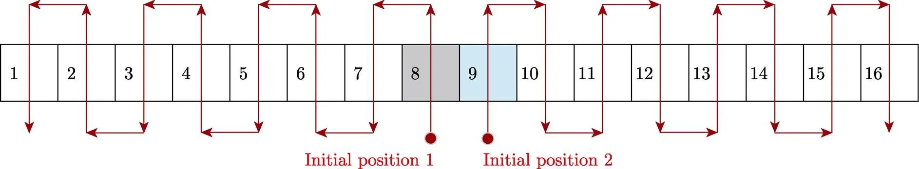
Fig. 8 Planning for whisk-broom path for the Moon
The TIS mainly consists of an optical machine main body, a comprehensive electrical box, and a cooler control circuit box. The composition and externalports the TIS system is shown in Figure 10.
4.1.3.2 GMI
To meet the imaging requirements under the city and town glimmer at night and of inshore multiple spectra during the daytime, a low-illumination CMOS detector and the off-axis TMA optical system with a small F-number are used and the technology system combining digital TDI push-broom with a large field of view and plane-array staring imaging is adopted. The digital TDI imaging mode is adopted by default to realize high-efficiency imaging with a large field of view, while for weak target signals, the staring imaging mode based on image motion compensation is adopted to increase exposure time and improve the detection capability. The imaging range of one camera is more than 150 km, with a ground pixel resolution of 10 m. A range of 300 km can be achieved by joining two cameras.
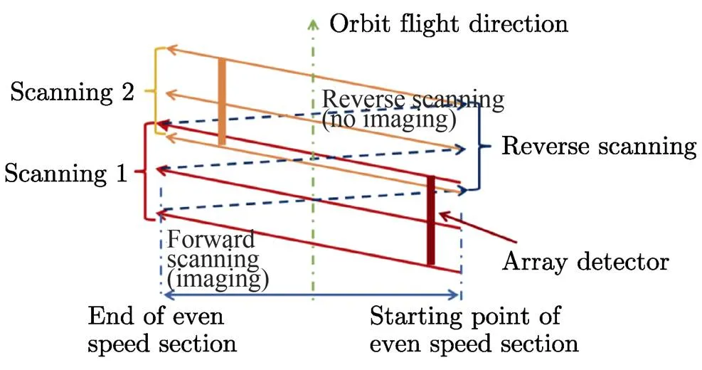
Fig. 9 Diagram of TIS whisk-broom
The GMI consists of the camera lens, the focusing plane assembly and the electrical control assembly. The overall structure of its components and external ports is shown in Figure 11.
Images of surface feature targets are formed on the focusing plane through the camera lens and then processed through on-satellite registration following photoelectric conversion. Image information is output through the imaging circuit. Image data are transmitted to the satellite DDT component for data compression and storage, sent to the ground station at a proper time after real-time or in-orbit storage, and processed by the ground application system.
4.1.4 Platform Solution
The satellite's containing structure is a rectangle. The center of the interconnection circle between the satellite and the rocket is defined as the coordinate origin, the direction that the payload lens is pointing in the interconnection plane is defined as the +direction (that is, the Earth-pointing direction of the general survey mode during in-orbit flight) and the direction perpendicular to the interconnection plane and pointing from the platform to the payload is the +direction (the flight direction in general survey mode during in-orbit flight). The satellite adopts three-axis stable attitude control, with the three axes stably pointing to fixed direction against the Earth in general survey mode. The sunlight mainly shines on the satellite from the –anddirections. When the satellite is placed on the ground, from top to bottom are the GMI, the TIS, and the satellite platform cabin, as shown in Figure 12.
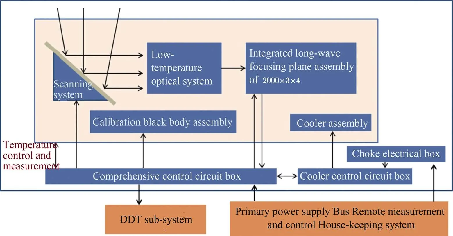
Fig. 10 Diagram of TIS system composition and external ports

Fig. 11 Diagram of GMI system composition and external ports
A single-wing fold-up solar panel is adopted for the satellite power supply. When the satellite is launched, the solar panel is folded up on theside board. The solar panel is unfolded and locked in theaxis direction after the satellite enters its orbit, with an angle of 30° between the solar panel and the –axis. The night side and +side are the heat dissipation sides of the payload, theside is the main heat dissipation side of the satellite platform, and +andsides are the auxiliary heat dissipation sides of the satellite platform, as shown in Figure 13.
The house-keeping computer is the satellite information management and control center which performs centralized management for on-satellite remote sensing data collection, flying program, attitude and orbit control, and thermal control. A power controller provides power supply and distribution for each computer in a uniform manner. The on-satellite payload DDT information flow centers on a multiplex modulator to perform data multiplexing, assembling frames, encoding, modulation, amplification, and downlink to ground stations through the antenna, and complete payload data and satellite platform data transmission. For DDT, the X band is adopted to realize scientific data downlink from the satellite to the ground at 2×810 Mbit·s-1.

Fig. 12 Diagram of the static satellite placed on ground
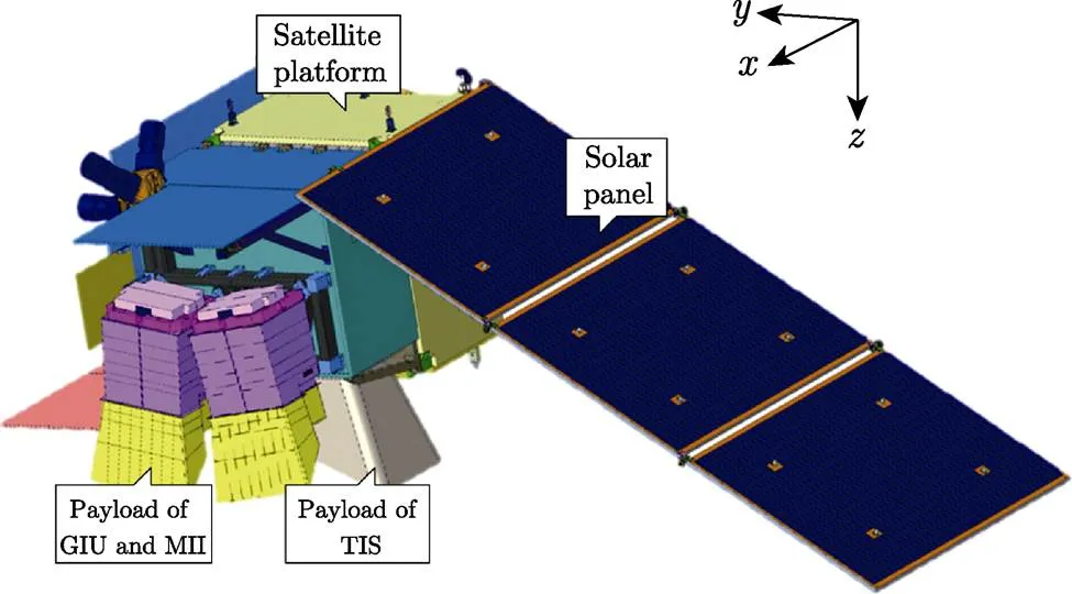
Fig. 13 In-orbit flying status diagram
The satellite time system is managed by a house- keeping computer uniformly. The computer supports functions such as time service, centralized time calibration, uniform time calibration, and GPS/Beidou time calibration. The computer keeps the time by itself after synchronization of GPS/Beidou time calibration and centralized time calibration on the ground.
The satellite adopts three-axis zero-momentum stability control and double star sensors and gyro EKF for attitude measurement accuracy of 10'', and uses angular momentum feed-forward to compensate for the impact of the movement of the thermal infrared oscillating mirror to meet the requirements of ground pointing accuracy of 0.08° and stability of 0.0012(°)·s-1.
The satellite dry weight is 715 kg, among which 355 kg is the payload weight and 15 kg is the fuel. The average power dissipation of the entire satellite is 576 W and the peak power dissipation is 1086 W.
4.2 Launch Vehicle and Launch Site
LM-6 is the New Generation innocuous and no-pollution launch vehicle, mainly used to launch satellites for various purposes to Sun-Synchronous Orbit (SSO) and Low-Earth Orbit (LEO).
The LM-6 uses three horizons(horizontal integral test, horizontal integral Satellite and Launch Vehicle docking, horizontal integral transportation and erection)test-launch mode,realizing quick test and launching (see Figure 14 and 15).
Launch Site is in Taiyuan Satellite Launch Center.
4.3 Measurement and Control System
Satellite ground TT&C system adopt the USB measurement and control mechanism for satellite tracking, range finding, orbit measurement, remote measurement, and remote control.
4.4 Ground Support System
The Ground Support System (GSS) is responsible for in-orbit operation management and services for the satellite, including satellite status monitoring and fault warnings, payload status monitoring, data reception plan preparation, scientific data reception, and forwarding and others.
The ground data reception station includes three X band reception stations in Miyun, Sanya, and Kashi. When necessary, use the Antarctic reception station to make up for the insufficient reception time. The technical indices are listed as follows.
(1) Operating band: X band.
(2) Polarization method: simultaneous left-handed+ right-handed circular polarization (data), left- handed/right-handed circular polarization self-adaption (tracking).
(3) Antenna aperture: 12 m.
(4) Antenna G/T value: 33.5 dB·K-1.
(5) Ground station reception rate: main 2× 810 Mbit·s-1(8 PSK) and emergency 2×540 Mbit·s-1(QPSK).
4.5 Scientific Application System
The Scientific Application System (SAS) is responsible for verifying scientific objectives, payload configuration solutions, satellite technology indices and usage requirements, constructing scientific application system software and hardware, producing and providing level 0~4 standard products, advanced products, and dedicated scientific application products as well as providing data support for scientific application research, realizing in-orbit on-satellite calibration through observation of the cold sky, on- satellite black bodies, LED lights, the Moon and other light sources or objects to obtain and provide calibration parameters and organizing in-orbit tests with the CASEarth satellite in the fields of panoramic beautiful China, the digital Belt and Road, 3D information ocean, biodiversity and ecological security, three poles and others.
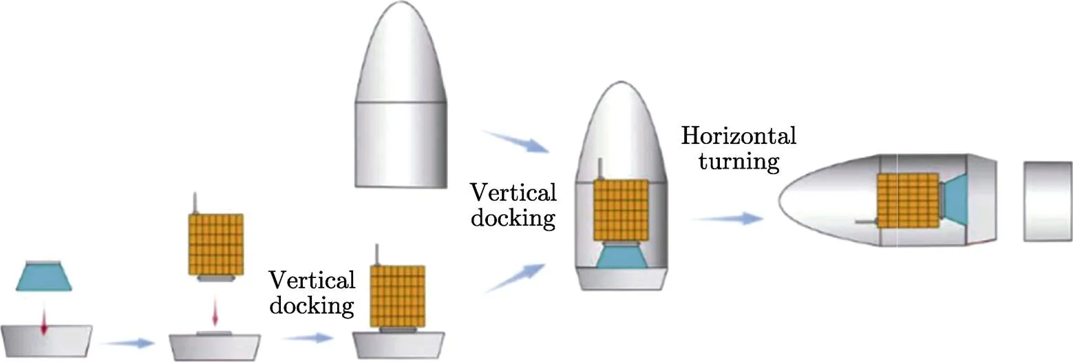
Fig. 14 Single satellite docking flow
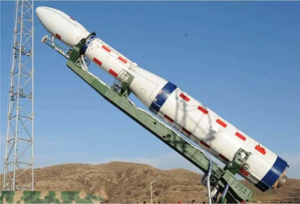
Fig. 15 LM-6 launch vehicle
5 Ground Reception and Data Processing
The ground part of the CASEarth satellite mainly consists of a measurement and control system, the ground support system, and the scientific application system.
The measurement and control system is responsible for receiving the payload control instructions from the ground support system and encode them and perform instruction transmission to the satellite through the S-band satellite ground measurement and control station, receiving remote measurement data of the satellite S-band and sending the data to the ground support system.
The ground support system is responsible for generating payload control instruction through payload imaging planning based on the scientific observation plan, receiving the satellite remote measurement data from the measurement and control system, analyzing and handling remote measurement data to monitor satellite status and payload status and give fault warnings, as well as receiving downlink DDT data of the X band from the satellite through the ground data reception station and sending them to the scientific application system.
The scientific application system is responsible for generating an observation plan based on the scientific observation requirements, receiving the satellite DDT data from the ground support system to handle data products, producing and providing level 0~4 standard products, advanced products and dedicated scientific application products, providing ground calibration parameters through ground calibration, collaborating with each dedicated applications of the dedicated Earth big data project, and providing high-quality data support for dedicated scientific application research.
6 Development Plan and Current Status
The satellite is now at the prototype phase and is scheduled to be launched at a proper time after May 2021. Data services will be available within half a year after the launch.
P 4
Guo Huadong, Chen Hongyu, Chen Liangfu, Fu Bihong. Progress on CASEarth Satellite Development., 2020, 40(5): 707-717. DOI:10.11728/cjss2020.05.707
* Supported by Chinese Academy of Sciences Strategic Leading Science and Technology Project (XDA19010000)
March 16, 2020
E-mail: liangdong@radi.ac.cn