Liutex-based vortex dynamics: A preliminary study *
Hai-dong Yu, Yi-qian Wang
1. School of Aerospace Engineering, Tsinghua University, Beijing 100084, China
2. School of Mathematical Science, Soochow University, Suzhou 215006, China
Abstract: Vortex dynamics, with the possibility of efficient flow control, is explored in this study based on the new introduced vortex definition and identification system of Liutex. With the six core elements of vortex identification, including (1) absolute strength, (2) relative strength, (3) local rotational axis, (4) global rotational axis, (5) vortex core size and (6) vortex boundary,provided by the Liutex system, it is possible to numerically devise strategies, primarily by introducing additional source terms in Navier-Stokes equations, which we call Liutex force field model here, to control the vortex regions. Two methodologies of centripetal force model and counter-rotation force model are preliminarily investigated in a cavitating flow around two-dimensional Clark-Y hydrofoil. It is found that Liutex based models are capable of illustrating the vortex dynamics and possibly strengthening or weakening the vortices.
Key words: Vortex dynamics, Liutex vector, flow control
The Liutex vector has been introduced by Liu et al.[1]to represent the rigid rotation part of fluid motion,and thus to unambiguously identify and visualize vortices. Substantial progresses have been made both in theoretical and application aspects ever since.Theoretically, the Liutex vector has clear physical meaning as its magnitude represents twice the angular velocity of rigid rotation part and its direction is the local rotational axis. In this way, the Liutex based vortex identification overcomes the shear contamination issue of previous scalar vortex identification methods, i.e., identifies vortices in pure shear flows.More importantly, the Liutex system introduces a new decomposition of fluid motion into rotation,represented by Liutex, pure shear and stretch and/or compression. It is also found that there exists a power spectrum similarity law regardless of high background shear presence[2], turbulent boundary layer for example, which endorses Liutex vector is a physical quantity that could be used to depict turbulent structures. For visualizing vortices, multiple methods have been proposed to illustrating vortices from different perspectives, including Liutex magnitude iso-surface,objective Liutex[3], Liutex-Omega method[4-5], and Liutex core line method[6-7], etc. which collectively have been proven efficient in capturing vortices in various flows. For more detailed summary on recent developments of Liutex system, please refer to Liu et al.[8], Wang et al.[9], Liu and Gao[10]and Liu et al.[11].
An important feature of the Liutex system is its capability to well provide the full six core elements of vortex identification, which serves as touchstones against which a vortex definition and identification system should be tested. (1) The absolute strength is the Liutex magnitude, representing twice the angular speed of the rigid rotation part of fluid motion. (2) The relative strength is given by the parameter of the Liutex-Omega method, understood as the rigidity of fluid motion. (3) The local rotational axis is the direction of Liutex vector. (4) The vortex rotation axis or the global axis is defined as the connected points that satisfies ∇R×r=0 and R>0, which has been introduced as Liutex core line method to extract vortex cores. (5) The vortex core size can be defined as a place where the relative rotational strength declined with 95% of the corresponding vortex core center point. (6) The boundary of a vortex is proposed to be ΩR=0.52, which can be applied to various flows without adjustment of thresholds. The six core elements lay the foundation on which our manipulating of vortices is constructed. These six core elements thoroughly depict vortices from various aspects and lay the foundation for quantitative analysis and possibly control of vortices.
Viewed as sinews and muscles of fluid motions[12], vortex dynamics plays a significant role in determining mass, momentum and heat transfer of flows. To study vortex dynamics based on the Liutex system, the first strategy would be to deduce the governing equations of Liutex vector, which, however,is not easy because of the eigenvector decomposition of the velocity gradient tensor involved in the definition of Liutex vector. Of course, simplification of the problem can be made with additional assumptions, inviscidity for example. A second strategy, which we adopted in this study, could be directly manipulating vortices based on the Liutex system, and investigating the response of the flow to the strengthening or weakening of certain vortices,and/or man-made new vortices, etc.. The principle goal of manipulating vortices here is to reveal the vortex dynamics behind the observation with potential indication of flow control. To be more precise, we add Liutex based source terms in the Navier-Stokes equations, which we call Liutex force field model here,then numerically simulate the flow to obtain the respondence, which may possibly deepen our understanding of the flow dynamics and/or guide us to more efficient physics-informed flow control.
The Clark-Y hydrofoil, with chord length c=0.07m and angle of attack α=8° is used in the current research to investigate Liutex force field models. The computational domain is consistent with the experimental water tunnel of Huang and Wang[13].The incoming flow velocity is 10 m/s and the cavitation number defined by the outlet pressure is 0.8.The simulation is implemented on OpenFOAM with the solver developed by Laboratory for Advanced Simulation of Turbulence (LAST) in Tsinghua University, including a novel cavitation model called nonlinear dynamic cavitation model (NDCM). For the reason of fundamental research, two-dimensional model is considered here, and the k-Ω-SST turbulence model is adopted.
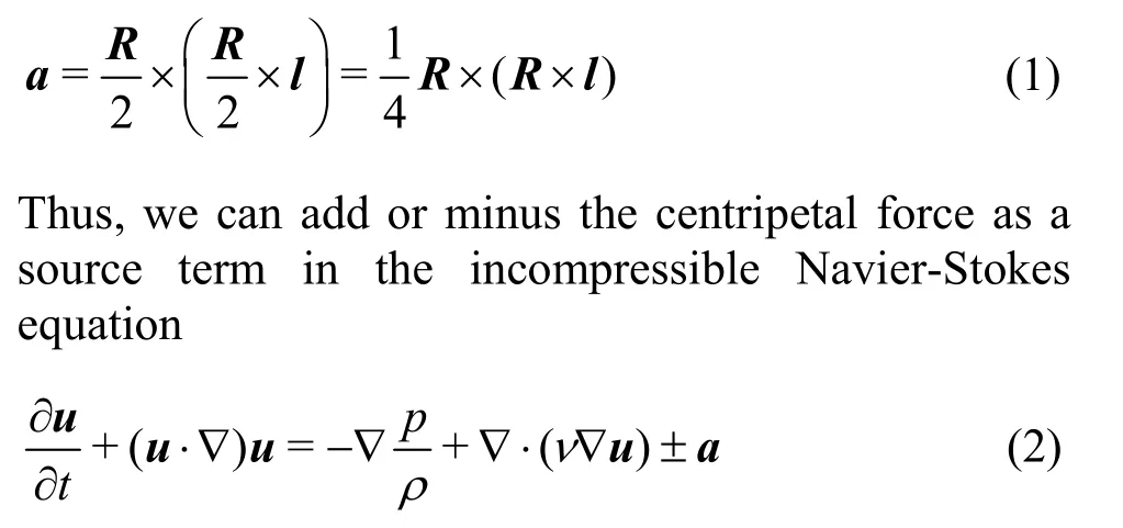
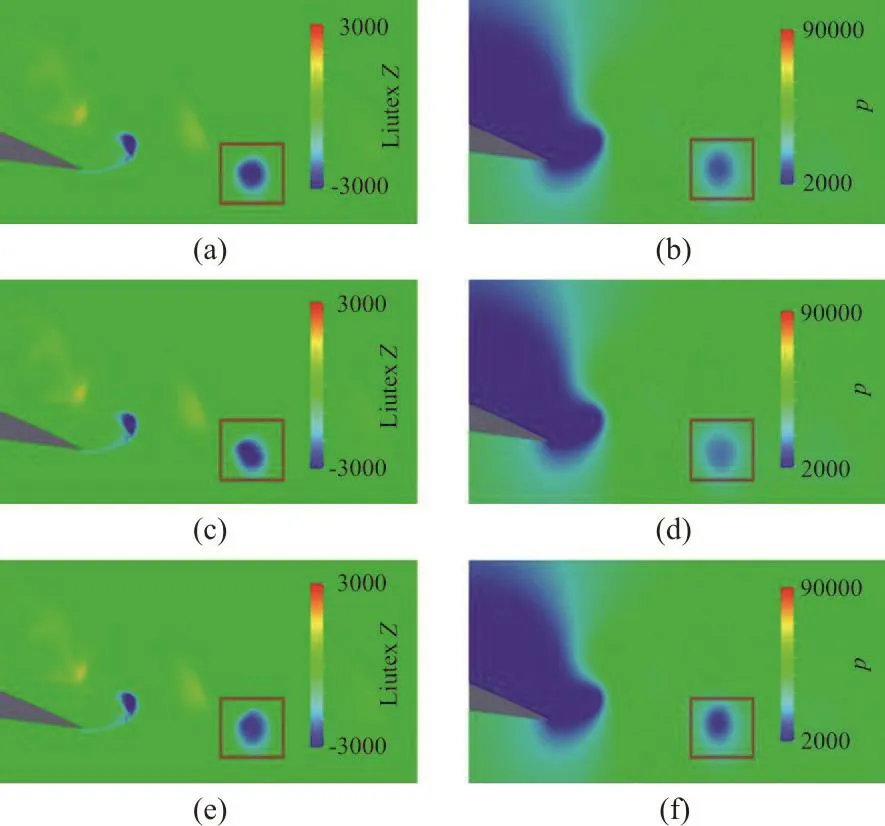
It has been realized that generally a local pressure minimum exists inside a vortex, which could be understood as the pressure gradient towards the rotation center provides the centripetal force for the fluids to rotate. As shown in Figures 1(a) and 1(b) the contours of Liutex and pressure, we can see the correspondence of vortices and pressure minimum in the wake of a Clark-Y hydrofoil with cavitation above the upper surface. We now focus on the vortex circumscribed with the red square, which has been shed off from the hydrofoil and free from high background shear and cavitation. Based on the reasoning above, we propose the centripetal force model to control the pressure minimum inside the vortex. First, the Liutex core line method is used to extract the vortex cores from the flow, which is actually the forth core element of vortex identification method. Then consider a point P inside the vortex region with corresponding vortex center0P on the Liutex core line. We thus define the vector pointing from0P to P as l which serves as the rotation radius. Next the angular velocity of the rigid rotation part of point P is taken as half the Liutex, i.e., R/2.Finally, the centripetal force (actually centripetal acceleration) can be obtained by

where u is the velocity vector while p, ρ and ν represent pressure, density and kinematic viscosity respectively. For compressible flow or multiphase flow with different density, the centripetal forces added to corresponding equation would be a multiplied by ρ.
Note that Eq. (1) to calculate centripetal force is written in vector form which can be directly used in three dimensional flows. We now focus on the vortex in the wake of a two dimensional Clark-Y hydrofoil that circumscribed by red square as shown in Fig. 1.The first row (Figs. 1(a) and 1(b)) is the uncontrolled case while the second row (Figs. 1(c) and 1(d)) and third row (Figs. 1(e) and 1(f)) are controlled cases with additionally adding and subtracting the centripetal force defined by Eq. (1) respectively.Notice that the additional source term is only applied around the considered vortex and the three cases are obtained from a same initial time at which the considered vortex is one diameter upstream where the additional force begin to be exerted. It can be observed from Figs. 1(a), 1(c) and 1(e) (contours of Liutex) that the intensity of the considered vortex basically remains the same whether or not centripetal force is added or subtracted, only to find that the shape is slightly altered. On the other hand, the adding of a provides part of the centripetal force for the fluids to rotate and thus alleviate the pressure gradient.Comparing Figs. 1(b) and 1(d), the pressure minimum inside the vortex increases from p≈12000 to p≈16000. On the contrary, subtracting a in Eq. (2)means that in addition to provide centripetal force for the fluids to rotate, the pressure gradient also has to balance out the exerted force. Therefore, the pressure minimum reaches as low as p≈7000. In hydrodynamics, flow region of low pressure is dangerous and prone to cavitate if the pressure is low enough. In particular, vortex cavitation is the kind of cavitation with low pressure caused by vortices. From the discussion above, maintaining an additional centripetal force could somehow attenuate the pressure minimum and thus alleviate vortex cavitation,which is destructive. In addition, the example illustrates that the pressure and vortex field(represented by Liutex) is somehow decoupled as the vortex changes little while pressure gradient noticeably attenuated or strengthened.

Fig. 1 (Color online) Centripetal force model applied to a vortex in the wake of Clark-Y hydrofoil
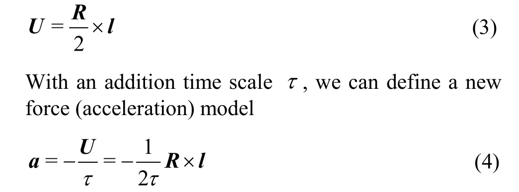
A second and more intuitive approach would be adding source terms in the Navier-Stokes equation to drive the fluids rotating in the counter direction to the rotational direction of vortices identified by Liutex system. The first step would be again using the Liutex core line method to recognize the vortex cores. Then form a vector l from corresponding center0P to the considered point P in the vortex region. With Liutex as twice the angular velocity of rigid rotation part of the flow, the rigid rotation velocity part can be obtained as Thus, τ acts like a relaxation time during which the rigid rotation part velocity could be decreased to zero,and the minus sign in Eq. (4) means that the force will always be the opposite of rigid velocity and thus holds back the rotational motion. The main principle to select τ is that it should not be too small to cause numerical instability while should not be too large to be trivial.

By trial and error, the time scale τ is selected to be about 1/20 of the shedding period T to control the vortex in the wake of Clark-Y hydrofoil. Shown in Figs. 2(a) and 2(b) (contours of Liutex and pressure)is a previous time step where the counter-rotation force model has not been added in the simulation,which actually is also the initial condition of all the cases in Fig. 1. The distributions of Liutex and pressure after exerting the counter-rotation force for t=1/40T are shown in Figs. 2(c) and 2(d). Clearly,the vortex has been almost cancelled out and thus the corresponding pressure minimum has been greatly eased to about 23 000. From the parameters selected in the paper, it seems that the second approach of counter-rotation force model is much more effective than the centripetal force model.

Fig. 2 (Color online) Counter-rotation model applied to a vortex in the wake of Clark-Y hydrofoil
The two models proposed here are just two illustrations of studying vortex dynamics based on forcing according to Liutex system. Many more strategies can be contrived based on the Liutex informed six core elements, which we collectively call Liutex force field models. For example, despite the cavitating flow around the Clark-Y hydrofoil is highly unsteady, it can be seen from Fig. 3 that in average there exists a clockwise rotating vortex above the tip region of the hydrofoil. It is thus attempting to see what will happen if we use the counter-rotation force model based on the time-averaged flow field (steady forcing). Figure 4(a) shows the magnitude of forcing(a), with direction of forcing anti-clockwise. After about 1/4 of shedding period T, a strong anticlockwise rotating vortex is formed as shown in Fig.4(b), which then attenuates and reforms as shown in Figs. 4(c) and 4(d) because of its interaction with the main stream flow and cavitation.

Fig. 3 (Color online) Time-averaged Liutex distribution around Clark-Y hydrofoil

Fig. 4 (Color online) Liutex-based standing vortex control
A preliminary investigation to study vortex dynamics in various flows based on the Liutex system is presented with a cavitating flow around twodimensional Clark-Y hydrofoil. Two methodologies of Liutex force field models, including centripetal force model and counter-rotation force model are proposed with applications to control a wake vortex.Although these models are hard to realize in engineering, vortex dynamics could be possibly revealed just as thought experiments in physics. With this idea in mind, we could contrive countless ways to modify the flow field as we wish based on the Liutex system and the six core elements in particular. Logic reasoning are also indispensable to help us select those methodologies promising to work. Viewed as sinews and muscles of fluid motion, it is of great importance to understand vortex dynamics which could lead us to understand and efficiently control the flow.
Even though we have diminished the application prospect of the methodologies in this research, hardly for sure can we be about the future. For example, it might be possible someday that particles entrained in vortex cores can exerted the centripetal forces needed for the fluids to rotate, and thus alleviate the pressure gradient and corresponding cavitation.
In summary, vortex dynamics in various flows can be studied through devising forcing models based on the Liutex system. And hopefully, the current preliminary work could lead to more systematic research and more meaningful results.
Acknowledgments
The enlightening discussions with Prof.Lian-di Zhou are highly appreciated which actually motivate the current research. We are also grateful to Profs. Chaoqun Liu and Zheng Ma for the valuable suggestions and comments on the manuscript.
- 水动力学研究与进展 B辑的其它文章
- Liutex core line and POD analysis on hairpin vortex formation in natural flow transition *
- Numerical study on the bubble dynamics in a broken confined domain *
- Flow characteristics in open channels with aquatic rigid vegetation *
- A study of the evolution of nanoparticle dynamics in a homogeneous isotropic turbulence flow via a DNS-TEMOM method *
- Numerical investigation on the drag force of a single bubble and bubble swarm *
- Local scour by multiple slit-type energy dissipaters *

