基于叠层滑移工艺的复合材料J形和C形梁成形技术
薛向晨 胡江波 王犇 曹正华 郑晓玲 孟庆功 梁宪珠
摘要:针对大型民用客机中复合材料零件的制造工艺,提出了一套基于叠层滑移工艺的复合材料骨架类零件自动化制造技术,利用叠层滑移工艺在将平面预形体变形成带圆角的立体预形体过程中没有褶皱的特点,形成了叠层滑移工艺制备复合材料J形和C形梁立体预形体的具体工艺方法。对于采用该技术制造的复合材料J形梁和C形梁,开展了内部缺陷、厚度和外观等常规检查,检查结果满足设计的要求;采用剖切的方法对制件的纤维面外褶皱进行检查,结果表明不同位置的截面厚度一致,厚度均匀,在圆角处铺层走向稳定,无纤维褶皱;采用逐层打磨的方法对制件的纤维面内弯曲进行检查,结果表明铺层中纤维准直,没有弯曲和开裂的情况。以上研究表明,与传统的手工铺叠工艺比较,基于叠层滑移工艺的复合材料J形和C形骨架零件自動化制造技术的工艺稳定性好、质量一致性高、成本较低,适合自动化批量生产。
关键词:复合材料;J形梁;C形梁;叠层滑移;褶皱;纤维屈曲;自动化
中图分类号:TB332文献标识码:ADOI:10.19452/j.issn1007-5453.2020.06.005
对于预浸料热压罐成形工艺来说,基本的制造流程是首先将预浸料料片制备成立体预形体,再放到固化模具上在热压罐中进行固化,立体预形体制备是复合材料构件制造过程中的关键工序之一。随着复合材料在航空工业应用的增长,复合材料零部件及结构制造自动化也将随之扩展,对大型复合材料构件的自动化应用技术需求愈来愈迫切[1-4]。国内制造商通过引进自动铺带和自动铺丝设备,已经实现了蒙皮预形体自动化制备的技术突破[5-6];国内外制造商针对大型C形截面的梁类构件,通过对构型、铺丝工艺和工装,以及预浸丝的工艺适用性等技术研究,实现了C形立体预形体自动化制备的技术突破[7-14]。
目前,波音787和空客A350飞机的产量已大致达到了150架份/年[15]。未来我国大型宽体客机如果按年产量50架份估算,那么每年需要等截面J形和C形梁的总长度将分别达到约12250m和14000m。因此,对该类产品的自动化生产技术的需求非常迫切。
由于截面尺寸小、带拐角等特点,手工铺叠长桁、梁等零件的立体预形体一直比较难以控制。为了提高产品的工艺稳定性和质量一致性,进一步提高生产效率和降低制造成本,航空工业复材的研究人员在基于叠层滑移工艺制备长桁立体预形体的基础上[16],开发了等截面J形和C形梁的立体预形体制备技术,实现了自动化、工程化制造。
本文以某大型飞机机身复合材料等截面J形和C形梁为研究对象,介绍了其成形的自动化技术、工艺验证及应用的情况。
1预形体制备
1.1构件介绍
J形和C形梁的典型结构如图1和图2所示。
1.2制造工艺方案和流程
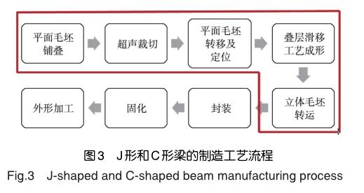
J形和C形梁的制造工艺方案如下:(1)采用自动铺叠工艺铺叠一个批次零件的大块平面预形体;(2)将大块平面预形体分切为若干个单块的平面预形体;(3)将单块的平面预形体转移至J形或C形梁预形体制备的专用设备中;(4)将平面预形体成形为立体预形体;(5)将立体预形体从设备中取出,运送至固化模具上;(6)将立体预形体封装在固化模具上,进热压罐中固化。
J形和C形梁的制造工艺流程如图3所示,其中的方框部分为本系列技术的重点研究对象。
1.3平面预形体铺叠与裁切
采用自动铺带或自动铺丝工艺铺叠出整块的预浸料平面预形体,然后采用超声切割刀将其分切为各个单块的平面预形体。
1.4平面预形体转运
因平面预形体易于变形,在转运时需要有辅助装置来保形。该辅助装置可将平面预形体从铺叠平台上转运至叠层滑移成形设备中,通过定位系统将平面预形体在各设备之间定位。
1.5平面预形体成形为立体预形体
(1)叠层滑移工艺与设备
叠层滑移工艺是将平面预形体经过缓慢的变形过程成形为立体预形体的过程。在这一过程中平面预形体内部相邻铺层之间要发生相对滑移,通过这种相对滑移运动来避免纤维褶皱的产生。
将平面预形体成形为立体预形体的叠层滑移工艺是由专用设备完成的。航空工业复材开发的基于叠层滑移工艺的J形和C形梁立体预形体制备设备如图4和图5所示。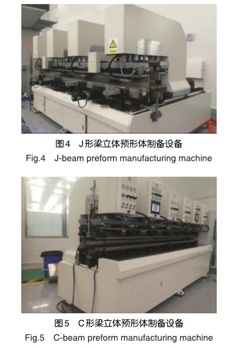
(2)预浸料树脂的流变性能
预浸料树脂的流变性能是影响预形体产生层间相对滑移的重要因素之一,选用预浸料树脂的等速升温黏—温曲线如图6所示,等温(135°C)黏—时曲线如图7所示。
(3)叠层滑移工艺的操作过程
第一步,将平面预形体放置于模头上并定位;第二步,对需成形的平面预形体进行加热并保温,保温温度和时间依据预浸料树脂的流变性能和试验验证结果确定;第三步,模头之间进行相对运动,使得平面预形体逐渐变形为需要的带折角的立体预形体。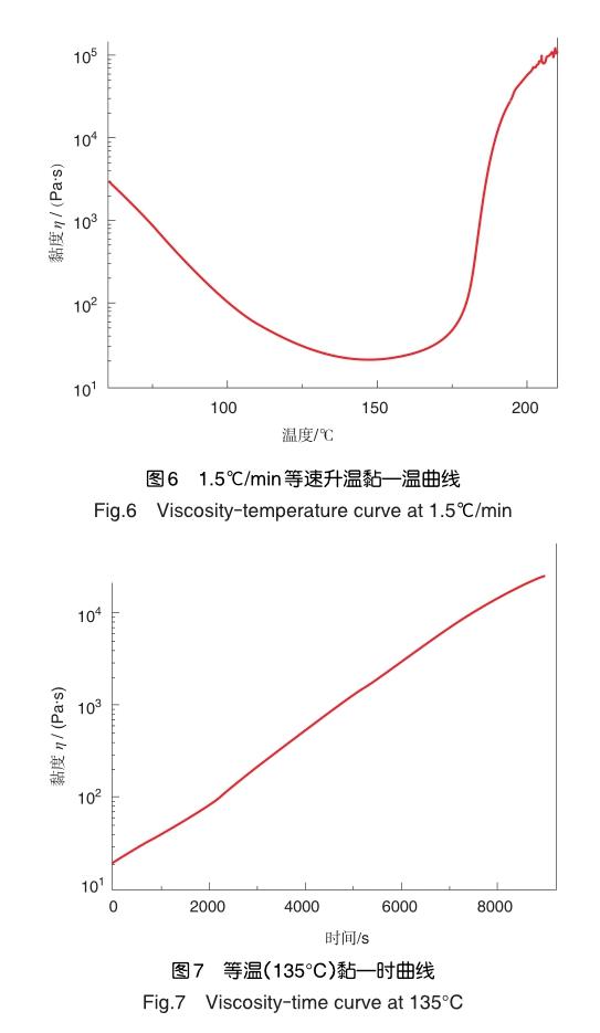
(4)J形和C形梁的立体预形体制备
J形梁立体预形体成形动作如图8所示;C形梁的立体预形体成形动作如图9所示。
1.6封装及固化
将J形梁和C形梁的立体预形体转移到固化模具上进行封装,如图10所示,封装后进热压罐固化,固化工艺曲线如图11所示(当压力达到0.14MPa时,将真空袋内真空降至-0.02MPa,直到固化结束)。
2结果与分析
2.1常规检测
(1)无损检测
对40余件J形梁和300余件C形梁试验件进行了全覆盖超声无损检测及孔隙率测试,未发现分层等超标缺陷,孔隙率≤1.5%。
(2)零件厚度
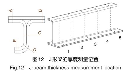
采用磁力测厚仪和超声测厚仪对40余件J形梁和300余件C形梁的厚度进行了检测,检测结果均满足设计要求的平面区±5%、圆角区±10%的指标要求。某批次梁的厚度测量位置如图12所示,测量结果如图13所示;C形梁的厚度测量位置如图14所示,测量结果如图15所示。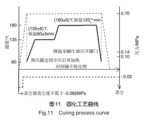
2.2破坏性检查
(1)铺层的面外褶皱
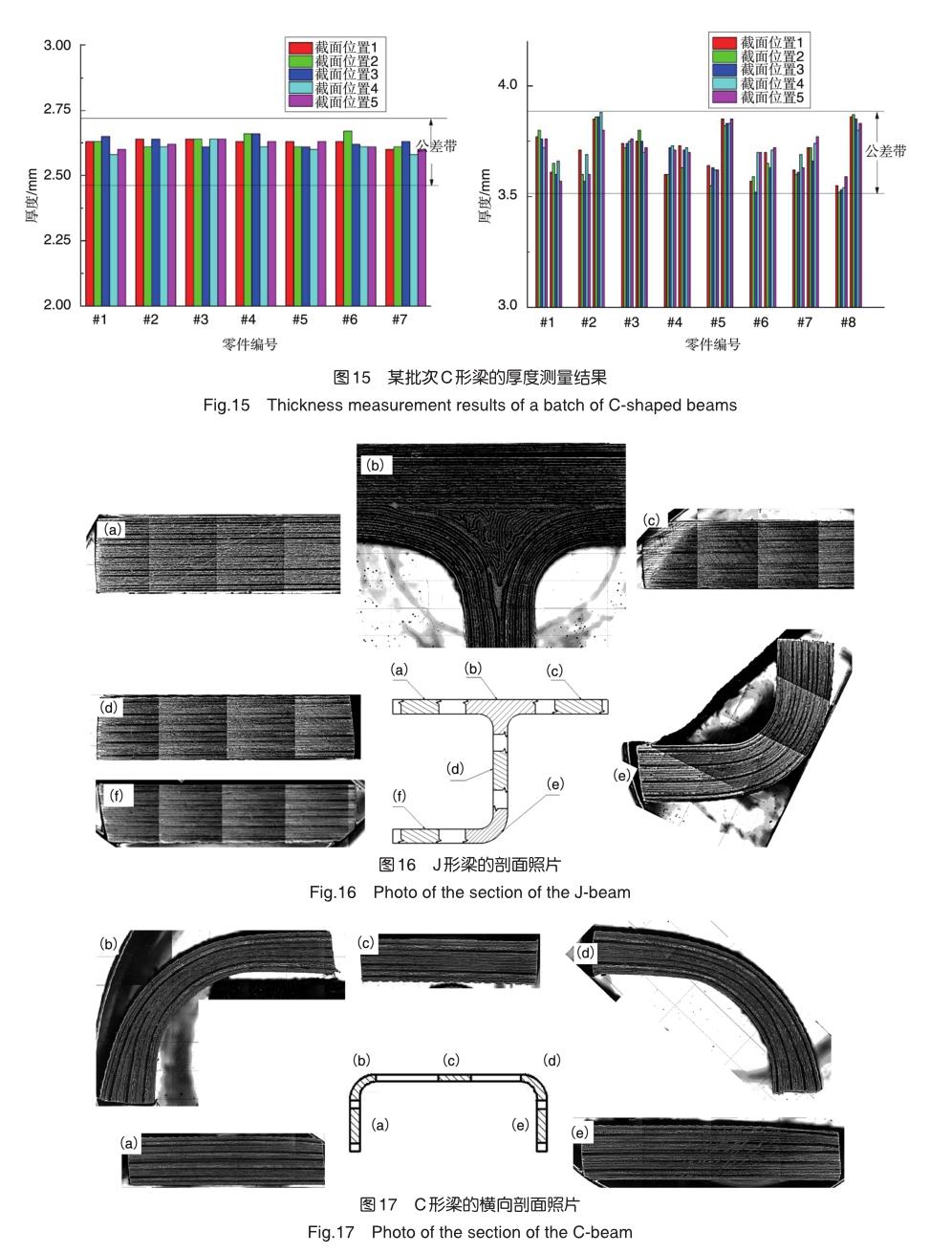
对J形梁和C形梁进行横向剖切,主要观察的各个圆角处的铺层是否有纤维褶皱,横向剖切位置与厚度测量的位置相同,典型的横向剖面的照片结果如图16和图17所示。
结果表明,不同位置的截面状态一致,厚度均匀,在圆角处铺层走向稳定,无纤维褶皱。
(2)纤维的面内弯曲
将平面预形体变形为立体预形体时,如果预形体层间的剪切力过大就会破坏原有的纤维状态,使得纤维在平面内出现弯曲或开裂[17]。
于是采用了逐层打磨的检查方法,来观察各个角度铺层的纤维走向。经过三件试验件的逐层打磨检查,被检查试验件内部的铺层中纤维准直,没有弯曲开裂的情况。
J形梁和C形梁的面内纤维检查位置与厚度测量的位置相同,典型面内纤维情况如图18和图19所示。
2.3叠层滑移的关键工艺参数
叠层滑移工艺是平面预形体经过不断的变形成为立体预形体的过程,在这一过程中预形体内相邻的铺层之间发生了相对的滑移,从而避免了褶皱的产生。
在这一过程中,主要控制的工艺参数是层间的相对滑移速度、平面预形体的温度和保温时间。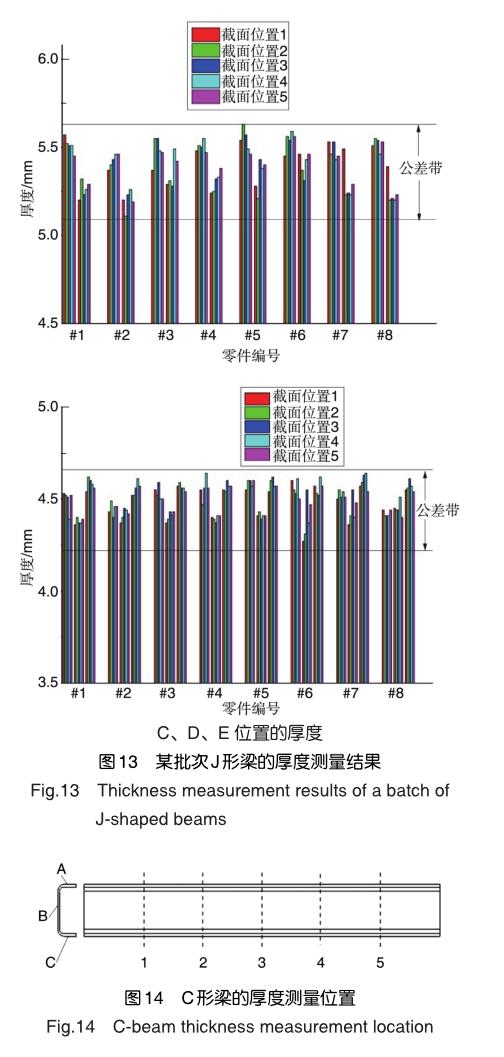
根据具体的J形梁和C形梁结构及铺层,并参考树脂本身的流变特性最终选取的工艺边界范围:相对滑移速度1.2~ 12mm/min之间;保温温度60~80℃之间;保温时间1~30min之间。
胡江波[17]等对该工艺参数范围内的叠层滑移工艺研究发现,该工艺虽然会影响层压板拉伸性能、压缩性能、弯曲性能、短梁剪切性能和面内剪切性能,但影响的程度有限,且通过选择合适的叠层滑移工艺参数,可以最大程度地降低该工艺的影响,很适合用在机体结构内部不会受到冲击载荷的长桁、梁等骨架结构上[18-25]。
3结束语
通过分析,可以得出以下结论:
(1)验证结果表明,采用基于叠层滑移的J形和C形梁的预形体制备工艺及专用成形设备,可以将预浸料平面预形体成形为立体预形体,工艺稳定,产品的质量一致性好。
(2)本文介绍的基于叠层滑移工艺的J形梁和C形梁预形体制备工艺与设备可以进一步开发为专用的工业化流水线;相对手工铺叠工艺成本低且效率高,具有非常大的竞争优势。
参考文献
[1]陈亚莉.航空复合材料自动化技术进展[J].航空科学技术, 2011(4):15-16. ChenYali.Developmentofautomationtechnologyfor aeronautical composites[J]. Aeronautical Science & Technology, 2011(4):15-16. (in Chinese)
[2]郝建伟.复合材料制造自动化技术发展[J].航空制造技术, 2010(17):17-20. Hao Jianwei. Development of automation technology for compositesmanufacturing[J].AeronauticalManufacturing Technology, 2010(17):17-20. (in Chinese)
[3]姚俊,孫达,姚振强,等.复合材料自动铺带技术现状与研究进展[J].机械设计与研究, 2011,27(4):60-65. Yao Jun, Sun Da, Yao Zhenqiang, et al. Current situation and research progress of automated tape-laying technology for composites[J]. Machine Design and Research,2011,27(4):60-65. (in Chinese)
[4]张建宝,王俊锋,孙宏杰,等.航天复合材料自动化成形技术研究现状[J].航空制造技术,2012(Z2):67-69. Zhang Jianbao, Wang Junfeng, Sun Hongjie, et al. Present research situation of composites automated processing technology in astronautics industry[J]. Aeronautical Manufacturing Technology, 2012(Z2):67-69. (in Chinese)
[5]刘亚威.连续纤维增材制造技术或将颠覆航空复合材料结构生产模式[J].航空科学技术, 2019, 30(8):77-78. Liu Yawei. Continuous fiber additive manufacturing technology may subvert aviation composite structure production mode[J]. Aeronautical Science & Technology, 2019, 30(8):77-78. (in Chinese)
[6]黄当明,聂海平.自动铺带技术在复合材料机翼蒙皮的应用[J].航空制造技术,2017(4):97-100. Huang Dangming, Nie Haiping. Application of automatic tape laying technology in the composites wing skin[J]. Aeronautical Manufacturing Technology, 2017(4):97-100. (in Chinese)
[7]林胜.自动铺带机/铺丝机(ATL/AFP):现代大型飞机制造的关键设备(上)[J].世界制造技术与装备市场,2009(4):84-89. Lin Sheng. ATL/AFP:the key machine for manufacturing of modern large airplane(A) [J]. Manufacturing Technology and Equipment Market, 2009(4):84-89. (in Chinese)
[8]林胜.自动铺带机/铺丝机(ATL/AFP):现代大型飞机制造的关键设备(中)[J].世界制造技术与装备市场,2009(5):90-95. Lin Sheng. ATL/AFP: the key machine for manufacturing of modern large airplane(B) [J]. Manufacturing Technology and Equipment Market, 2009(5):90-95. (in Chinese)
[9]林胜.自动铺带机/铺丝机(ATL/AFP):现代大型飞机制造的关键设备(下)[J].世界制造技术与装备市场,2009(6):78-83. Lin Sheng. ATL/AFP:the key machine for manufacturing of modern large airplane(C) [J]. Manufacturing Technology and Equipment Market, 2009(6):78-83. (in Chinese)
[10]肖军,张建宝,李勇,等.自动铺带技术研究现状[J].航空制造技术,2008(S1):126-128. Xiao Jun, Zhang Jianbao, Li Yong, et al. Research status of automatic tape-laying technology[J]. Aeronautical Manufacturing Technology, 2008(S1):126-128. (in Chinese)
[11]石林.自动铺丝束在航空工业中的应用现状[J].航空制造工程,1997(9):11-13. Shi Lin. Application status of AFP in aviation industry[J]. Aeronautical Manufacturing Engineering, 1997(9): 11-13. (in Chinese)
[12]孙成.复合材料翼梁自动铺丝技术研究[D].南京:南京航空航天大学,2013. Sun Cheng. Research on automated fiber placement technology of composite wing spar[D]. Nanjing: Nanjing University of Aeronautics andAstronautics, 2013. (in Chinese)
[13]方宜武,王显峰,肖军,等.基于变角度算法的复合材料翼梁自动铺丝[J].航空制造技术,2014(16):90-94. Fang Yiwu, Wang Xianfeng, Xiao Jun, et al. AFP of composite wing spar based on fiber steering algorithm[J]. Aeronautical Manufacturing Technology, 2014(16):90-94. (in Chinese)
[14]方宜武.基于測地线算法的复合材料翼梁自动铺丝技术研究[D].南京:南京航空航天大学,2014. Fang Yiwu. Research on automated fiber placement technology of composite wing spar based on geodesic algorithm[D]. Nanjing: Nanjing University of Aeronautics and Astronautics, 2014. (in Chinese)
[15]徐德康.波音和空客的新策略[J].航空维修与工程,2018(3): 15-17. Xv Dekang. The next step strategies for Boeing and Airbus[J]. Aviation Maintenance & Engineering, 2018(3): 15-17. (in Chinese)
[16]薛向晨,胡江波,王犇,等.叠层滑移工艺制造大型机身帽型长桁[J].航空制造技术,2020,63(4):62-67. Xue Xiangchen, Hu Jiangbo, Wang Ben, et al. Laminated slip manufacture method for large fuselage hat-section stringer[J]. Aeronautical Manufacturing Technology, 2020, 63(4): 62-67. (in Chinese)
[17]胡江波,薛向晨,郑晓玲,等.叠层滑移工艺对M21C层压板力学性能的影响[EB/OL]. (2020-04-11).https://doi.org/10.13801/ j.cnki.fhclxb.20190816.001. Hu Jiangbo, Xue Xiangchen, Zheng Xiaoling, et al. Influence of stack slippage process on mechanical properties of M21C laminates[EB/OL]. (2020-04-11). https://doi. org/10.13801/j. cnki. fhclxb.20190816.001.(in Chinese)
[18]王松,房晓斌,艾明.复合材料J型梁R区皱褶的消除[J].粘接, 2019,40(3):55-57. Wang Song, Fang Xiaobin, Ai Ming, Elimination of R-region wrinkles in composite J-beam[J]. Adhesion,2019,40(3):55-57. (in Chinese)
[19]Shuang Y,Xiaoxing M . Hot diaphragm forming of carbon fiber compositewithC-shapedstructure[J].JournalofBeijing University of Aeronautics and Astronautics,2013,39(1):95-99+104.
[20]王永军,杨凯,陈森林,等.热固性碳纤维编织复合材料C形结构隔膜成形工艺[J].玻璃钢/复合材料,2015(3):59-65. Wang Yongjun, Yang Kai, Chen Senlin, et al. Hot-diaphragm forming of the thermosetting carbon woven fabric composite withC-shapedstructure[J].FiberReinforcedPlastics/ Composites,2015(3):59-65 (in Chinese)
[21]房曉斌,郭俊刚,王宏博,等.浅谈复合材料C型梁的制造工艺[J].粘接,2019,40(1):50-53+57. Fang Xiaobin, Guo Jungang, Wang Hongbo, et al. A brief discussion on manufacturing process of composite C-shaped beam[J].Adhesion, 2019,40(1):50-53+57. (in Chinese)
[22]刘顺臻,姜洪博,王韬,等.复合材料主承力构件后压力框制造技术研究[J].航空科学技术, 2019(7):40-46. Liu Shunzhen, Jiang Hongbo, Wang Tao, et al. Study on manufacturing technology of composite primary-load-carrying rear pressure bulkhead[J]. Aeronautical Science & Technology,2019(7):40-46. (in Chinese)
[23]Sun J,Gu Y,Li M,et al. Effect of forming temperature on the quality of hot diaphragm formed C-shaped thermosetting composite laminates[J]. Journal of Reinforced Plastics & Composites,2012,31(16):1074-1087.
[24]胡江波,薛向晨,梁宪珠.一种复合材料J形毛坯的成形方法及成形工装:中国, ZL20180316809.3[P]. 2018-09-18. Hu Jiangbo, Xue Xiangchen, Liang Xianzhu. Forming method and forming tool for composite material J-shaped blank: China, ZL20180316809.3[P]. 2018-09-18.(in Chinese)
[25]Depase E P,Grubbs C V,Zenkner G C. Method and tools for fabricating composite beams:United States,US7754045[P]. 2010-07-13.(责任编辑陈东晓)
作者简介
薛向晨(1983-)男,硕士,高级工程师。主要研究方向:复合材料成形工艺。
Tel:18911984072E-mail:c31050201@sina.com
Manufacture Technology of Composite J-section and C-section Beam Based on Laminated Sliding Process
Xue Xiangchen1,*,Hu Jiangbo1,Wang Ben1,Cao Zhenghua1,Zheng Xiaoling2,Meng Qinggong2,Liang Xianzhu1
1. AVIC Composite Corporation Ltd.,Beijing 101300,China
2. Shanghai Aircraft Design and Research Institute,Shanghai 200436,China
Abstract: Aiming at the manufacturing process of composite material parts in large commercial aircraft, a series of automatic manufacturing technology of composite material frame parts based on the laminated slip is proposed. The laminated slip process is used to transform the flat blank into a three-dimensional blank with rounded corners. There is no wrinkle in the process, and a specific process method for preparing the composite material J-shaped and Cshaped beam three-dimensional preform is formed. For composite J-beams and C-beams manufactured with this technology, routine inspections such as internal defects, thickness and appearance were carried out, and the inspection results meet the design requirements. The method of sectioning was used to check the out-of-plane fiber wrinkle of the parts. The results shows that the thickness of the cross-sections at different positions is the same and the thickness is uniform. The pavement at the rounded corners is stable and no fiber folds exist. The layer-by-layer peeling off is used to check the fiber in-plane distortion of the parts and the results shows that the fibers in the layup are collimated without distortion or cracking. The above research shows that, compared with the traditional manual layup process, the automatic manufacturing technology of composite material J-shaped and C-shaped skeleton parts based on the laminated slip process has good process stability, high quality consistency, low cost, and is suitable for automated batch production.
Key Words: composites; J-section beam; C-section beam; laminated sliding; wrinkle; distortion; automation

